week-11 Joint creation and Demonstration
Objective,
To create the different types of joints like translational, revolute, cylindrical, and spherical joints. That joints are created between the two rigid bodies in Ls-Dyna. The behavior of the joint can be established using keywords.
Procedure,
A mechanical joint is a section of a machine which is used to connect one or more mechanical part to another. Mechanical joints may be temporary or permanent, most types are designed to be disassembled. Most mechanical joints are designed to allow relative movement of these mechanical parts of the machine in one DOF and restrict movement in one or more others.
Cylindrical Joint
A cylindrical joint is a two-DOF kinematic pair used in mechanisms. Cylindrical joints provide single-axis sliding function as well as a single axis rotation, providing a way for two rigid bodies to translate and rotate freely. This can be pictured by an unsecured axle mounted on a chassis, as it may freely rotate and translate.
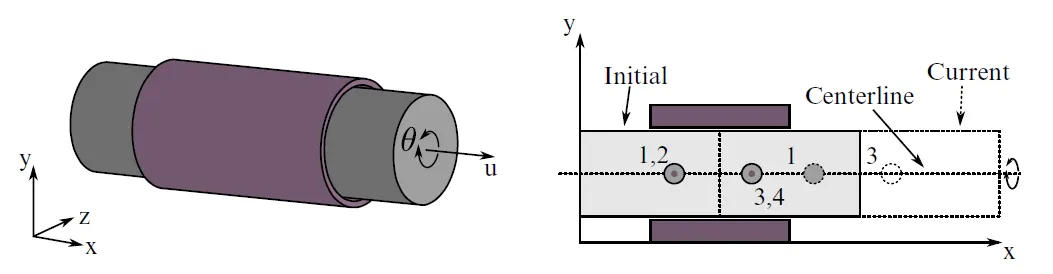
Fig. Cylindrical joints with nodes 1,2 as one pair and 3,4 as another pair
The cylindrical joint has 2 DOF, it can be rotated about a single axis and translational along the single axis. The inner cylinder can rotate about x and translate along the x-axis.
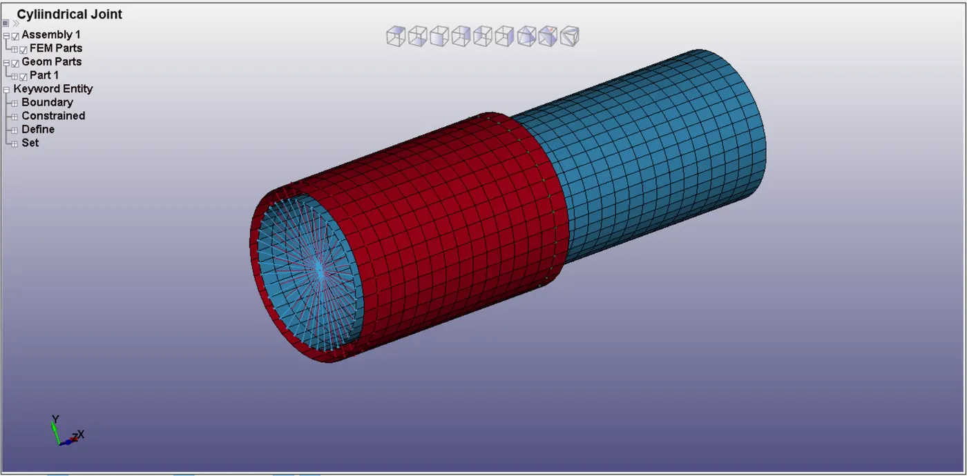
Fig. Cylindrical joint with 1802,1801 forms as one pair and 1803,1804 forms as the another pair
The figure shows the cylindrical joint in ls-Dyna, and the axis of rotation and translational at x-axis. Nodes from the nodal pair 1802,1801 and 1803,1804 coincide with each other. These nodes are located in the outside respective bodies. A node-set created where node 1801 and 1803 grouped to fixed one and 1802 and 1804 grouped to moving body. Further nodes of moving and fixed bodies are assigned to the particular part using the *CONSTRAINED_EXTRA_NODES_SET.
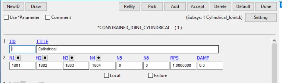
Fig. CONSTRAINED_JOINT_CYLINDRICAL keyword
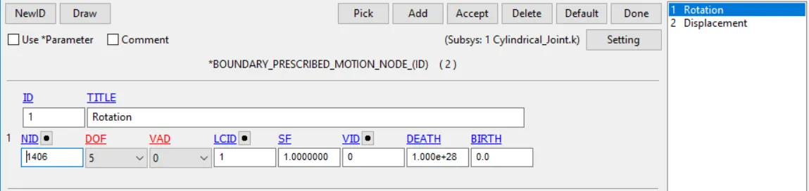
Fig. Velocity and Rotational assigned this keyword
The figure shows the nodes assigned to the form of the cylindrical joint. The initial velocity is given to the inner cylinder by using the *INITIAL_VELOCITY_RIGID_BODY keyword and rotational velocity also assigned to it. And assign the termination time and control time step keyword is used with a load curve for the maximum time step.
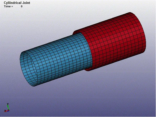
Fig. Simulation of Cylindrical Joint
Revolute Joint
A revolute joint (also called pin joint or hinge joint) is a one-DOF kinematic pair used frequently in mechanisms and machines. The joint constrains the motion of two bodies to the pure rotation along a common axis.
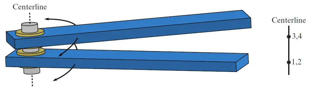
Fig. Revolute joint with nodes 1,2 as one pair and 3,4 as another pair
Revolute joints also called the hinge joint has one degree of freedom. Revolute joint with two nodal pairs formed by nodes 1,2 and 3,4.
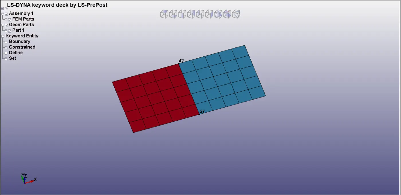
Fig. Revolute joint 31,37 form as one pair and 36,42 form as another pair
The figure showed the revolute joint in ls-Dyna. Shell section is assigned to the element and the thickness value is 1mm and *MAT_RIGID material card is assigned for defining the material card properties. the axis of rotation for this model is Y-axis. *LOAD_NODE_POINT keywords assigned at the point load to nodes 1 and 2 and the constant load is given through the load curve definition.
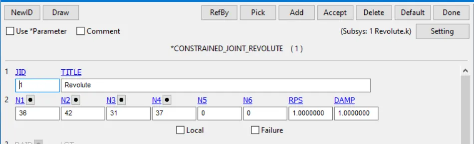
Two pairs of nodes as discussed above are considered to the revolute joint. where the node pair 36,31 and 42,37 coincide with each other. Assign the termination time and the control time step is used with a load curve for the maximum time step.
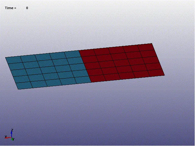
Fig. Simulation of Revolute Joint
Spherical Joint
Three Degrees of Freedom (Spherical) Joint Multi-degrees-of-freedom (DOF) actuators are widely used in several industries. In an automobile, ball joints are spherical bearing that connects the control arms to the steering knuckles.
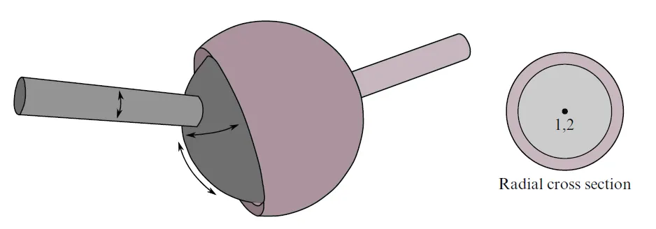
Fig. Spherical joint with node pair 1 and 2
spherical joint called a ball joint, their nodal points 1 and 2 coincide in the configuration. It allows the smooth movement in all the direction. where shell element is created using the shape of mesh option available in the element.
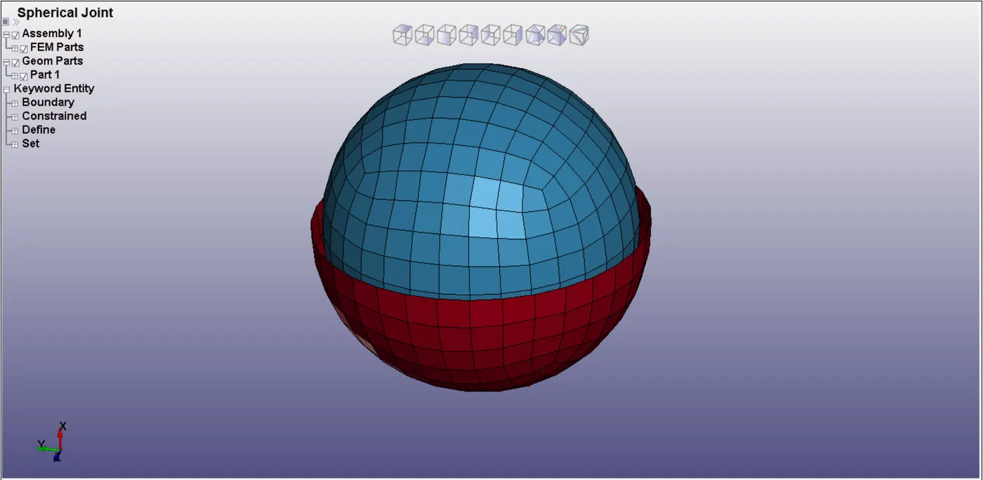
Fig. Spherical joint with a nodal point as 780 and 781
*CONSTRAINED_NODAL_RIGID_BODY used to assign the particular node to either a rigid body. *LOAD_NODE_POINT keywords assigned at the point load to nodes and the constant load is given through the load curve definition.
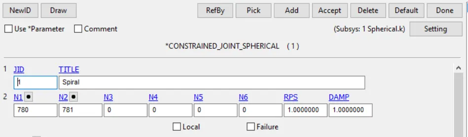
Two pairs of nodes as discussed above are considered to the spherical joint. where the node pair 780 and 781 coincide with each other. Assign the termination time and the control time step is used with a load curve for the maximum time step.
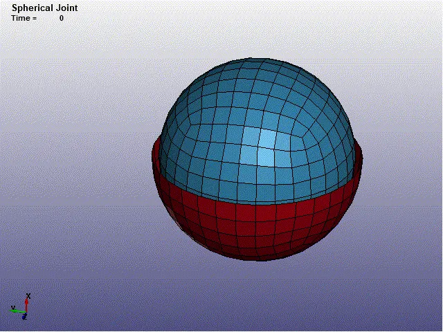
Fig. Simulation of Spherical Joint
Translational Joint
A translational joint allows one part to translate along a vector concerning another part. The parts can only translate, not rotate, in respect of each other. This joint has one translational degree of freedom, and the rotational degree of freedom is 0.
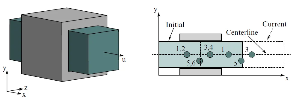
Fig. Translational joints with node 1,2 are 1st pair, 3 & 4 as 2nd pair, 5 & 6 as 3rd pair
The nodal pair 1,2 and 3,4 and 5,6 should coincide. It can only translate and can't rotate. The nodes of the nodal pair 5610, 5609 and 5612, 5611, and 5615,5613 coincide respectively. 5609,5611,5613 are referred to as moving parts at the inner cube.
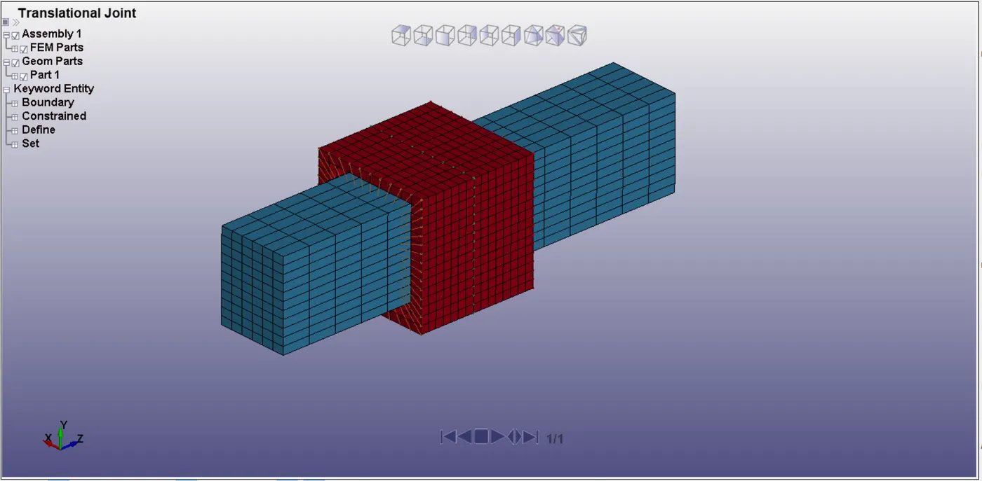
Fig. Translational joint with nodes 5610,5609 and 5612,5611 and 5613,5615
The inner box is the displacement at x-direction. *BOUNDARY_PRESCRIBED_MOTION_RIGID card assign for displacement. And termination time is defined and the control time step keyword is used with a load curve for the maximum time step.
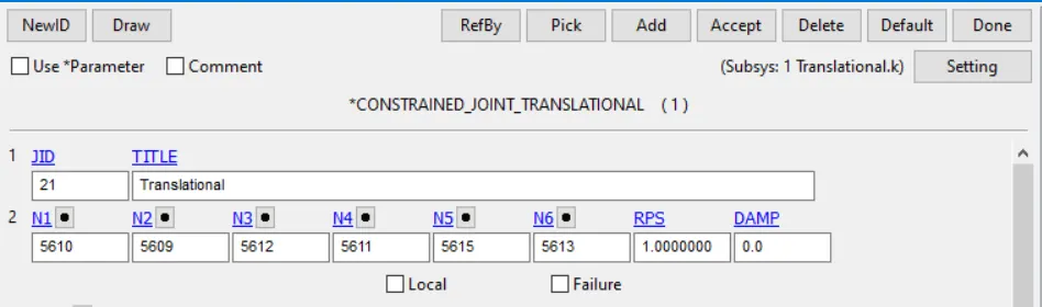
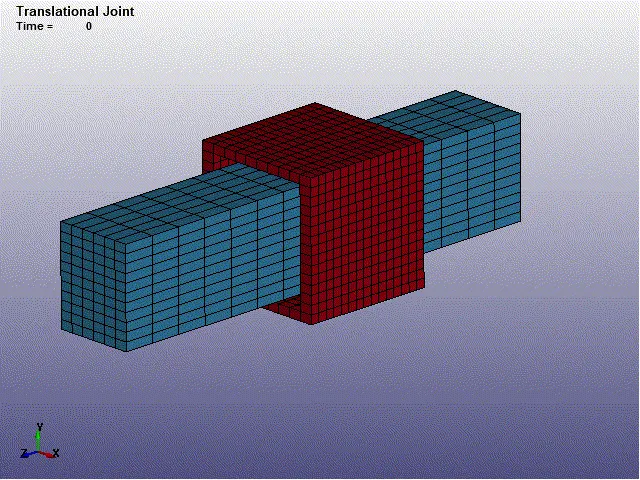
Fig. Simulation of Translational Joint
Conclusion,
All the joints spherical, revolute, cylindrical, and translational has been created and demonstrated using the constrained_extra_nodes and CNRBs respectively in Ls-Dyna