Joint creation and Demonstration in Ls Dyna
AIM
Create the appropriate meshed componenets and illastrate the creation of translational,cylindrical,spherical and revolute joints in Ls Dyna
OBJECTIVE
To getting to clearly know how the important types of joints such as cylindrical,translational,spherical adn revolute joints works in ls dyna and how we can create those joints in ls dyna with the proper keywords.
Procedure
1) REVOLUTE JOINT
Revolute joints have one degrre of freedom which is a rotational degree of freedom about an axis.To make the revolute joint abpout an axis we need to create have the nodes which represent the axis of the rotation.It is explained in Ls dyna manual how we can select the nodes and how we can asign it to use as an axis.
first we need to create an L shaped plate by the use of Shapemesher.We can use 4N Shell option and inpput the approproiate cordinates to create the L shaped bracket which are set at some distance apart .
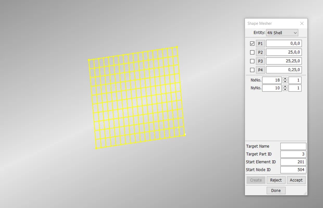
Creation of shell mesh with shape mesher
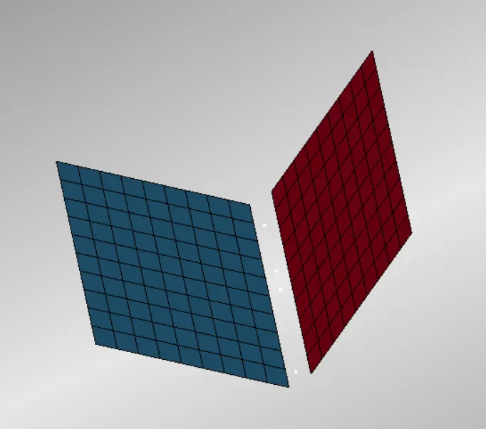
Component for revolute joint creation
Now we can define the Rigid material and section shell with some thickness in each part.Then to define the revolutejoint we need to have 4 nodes ,let it be 1,2,3,4 .Out of which 1,3 must be part of the rigid body 1 and 2,4 must be the part of rigid body B.And the 1,2 must be coincident and 3,4 also must be coincindent.inaddition to it this joint needes the 1,2,3,4 must be in same line which define the axis of rotation.
First we need to create the nodes 1,2,3,4 .For this we can use the Node edit tool inside tool bar and we can create the nodes in between the parts.We need to first define those appropriate nodes to the relevant part.For this we need to use the CONSTRAINED _EXTRA_NODE_SET .we need to create two node set in which 1,3 must be in one node set an 2,4 in other node set.Then we can use the create entity tool to create the constrained joint.Then choose revolute joint.,then select the nodes carefully in such a way that the nodes N1 , N3 must be the nodes which are part of rigid body 1 and the other two must be part of rigid body B.
Finally we ned to coincide the nodes.for that using Node editing ,there is tool called move.using it we can make the nodes coincide each other about the axis of rotation.Finally we need to get the bounary condition,her we give a prescribed motion set after defining a curve.Then control termintion and data base binary plot can be inputted to get the animation.
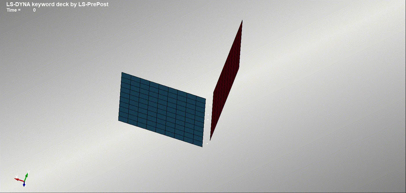
Simulation of revolute Joint
2)TRANSLATION JOINT
This joint is having a tranlastional Degree of Freedom,rest all degree of freedom is arrested.This is prepared similar to the revoluite joint .But her for arresting the rotation we need to use an extra pair of node set which is non collinear to the other two pair of nodes and this pair must be in between the other two pairs.First we prepared the Box shell componenet for making the translational joint.Then similar to like we done in revolute joint we create three pair of nodes and in which we create three pair of node set and we define three nodes in one same line as one set and three nodes in other side as other set.Then we can use the constrained extra node set card to assign the node set to rigid body.then we can create tranlastional joint using create entity tool.Here we will be selecting nodes such that N5 and N6 must be in between the other set of nodes.Then while coinciding the nodes we need to coincide the 5 and 6 nodes in such a way that it doesn't fall in the centre line.
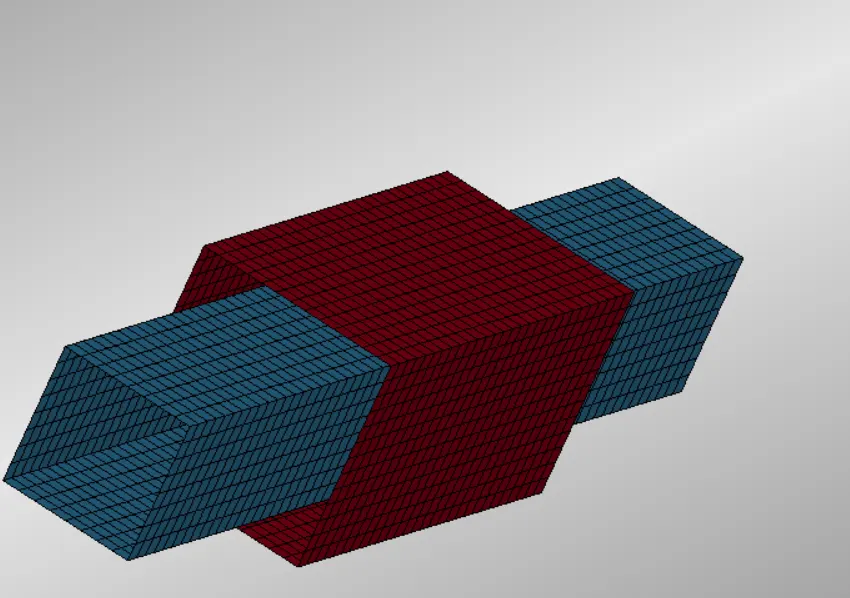
Component for Translational Joint Creation
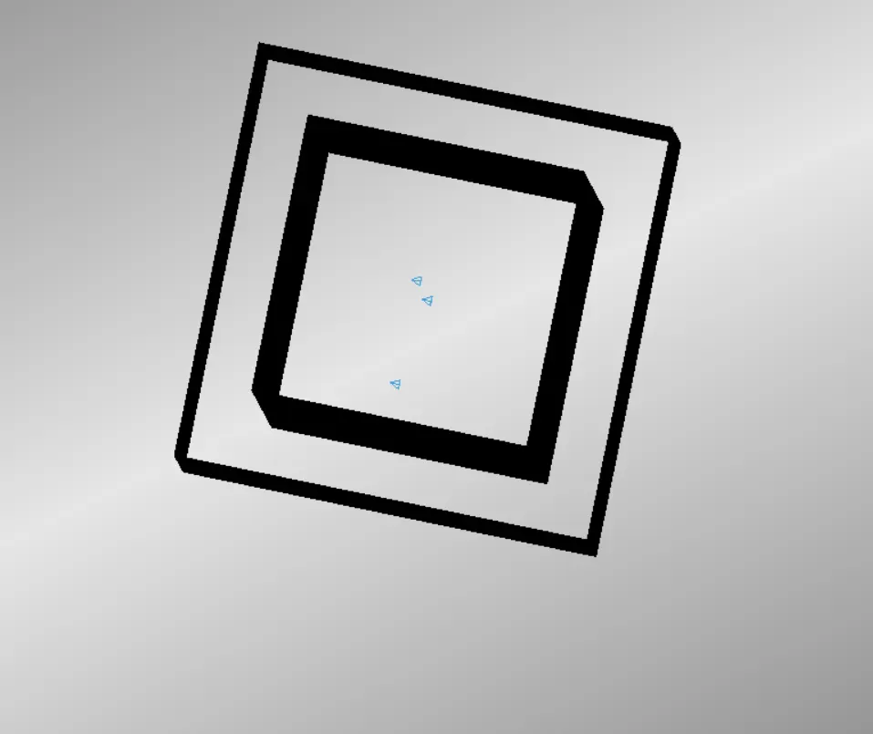
Nodes 5,6 not alligned with the other nodes for restricing the rotation in joint
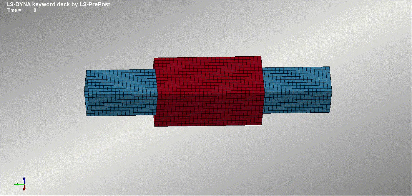
Simulation of tranlational Joint
CYLINDRICAL JOINT
Cylindrical joint is having two degree of freedom.This includes one axis of rotation and one axis of translation.The component is created using Cylinder shell mesh creation using the Shape mesher tool.
Cylindrical Joint is similar to revolute joint itself.Nodes 1,2,3,4 are need to be create and assign twonodes part of one rigid body and other parts of other rigid body using the constrained extra node set.Then using create entity we can create cylindrical joint in which the nodes 1 ,3 must be from rigid body 1 and nodes 2 , 4 must be from rigid body 2.And coincide the nodes like in revolute joint creation,so that the axis of rotation is assigned using it.then we can use the INTIAL_RIGIID BODY card to define the velocity of rotation and velocity of tranlastlation.
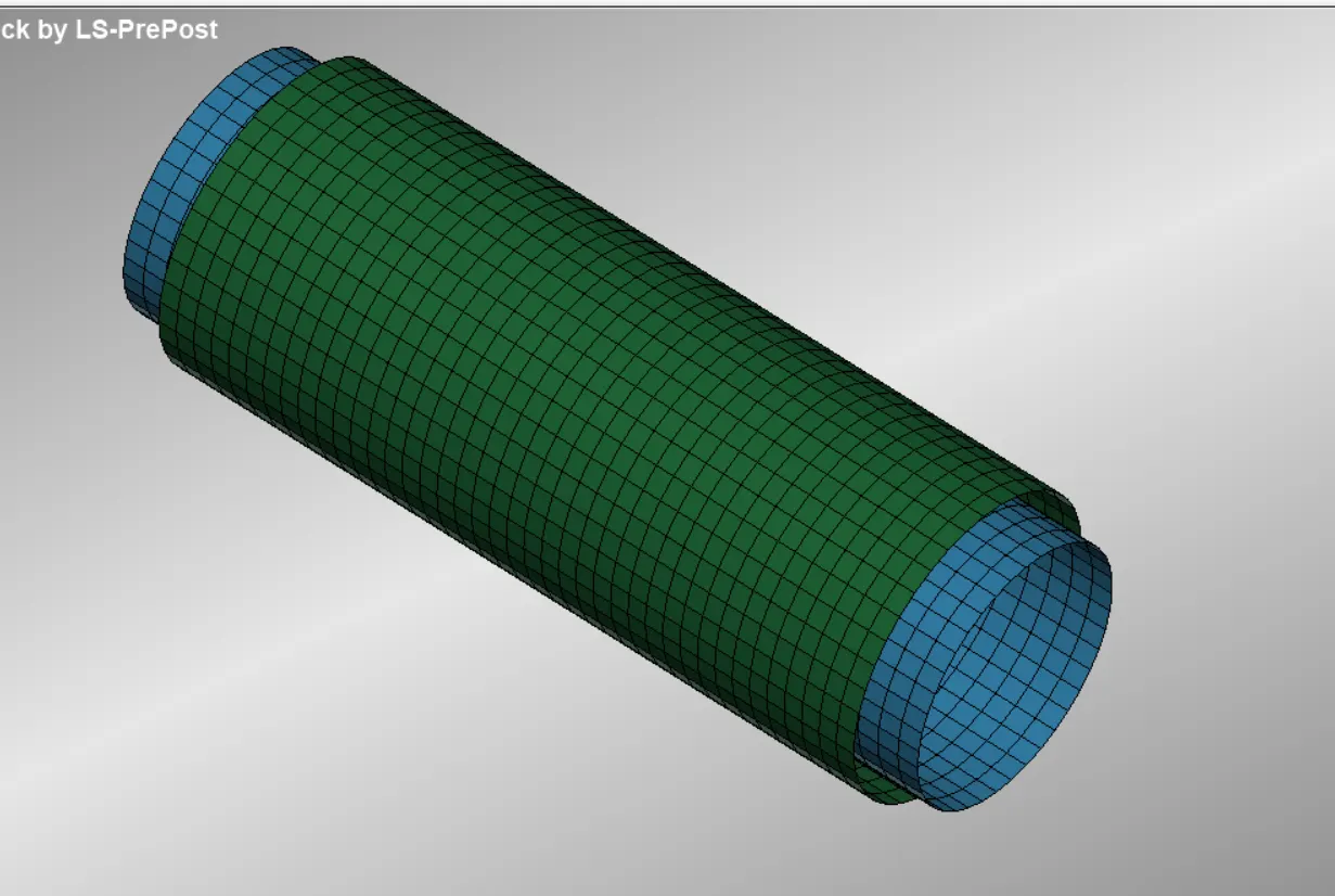
Component Created for cylindrical Joint creation
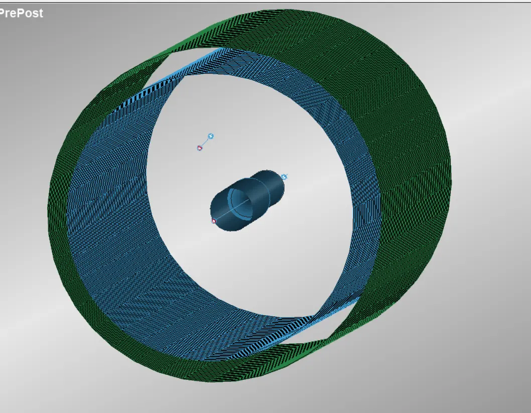
Cylindrical Joint
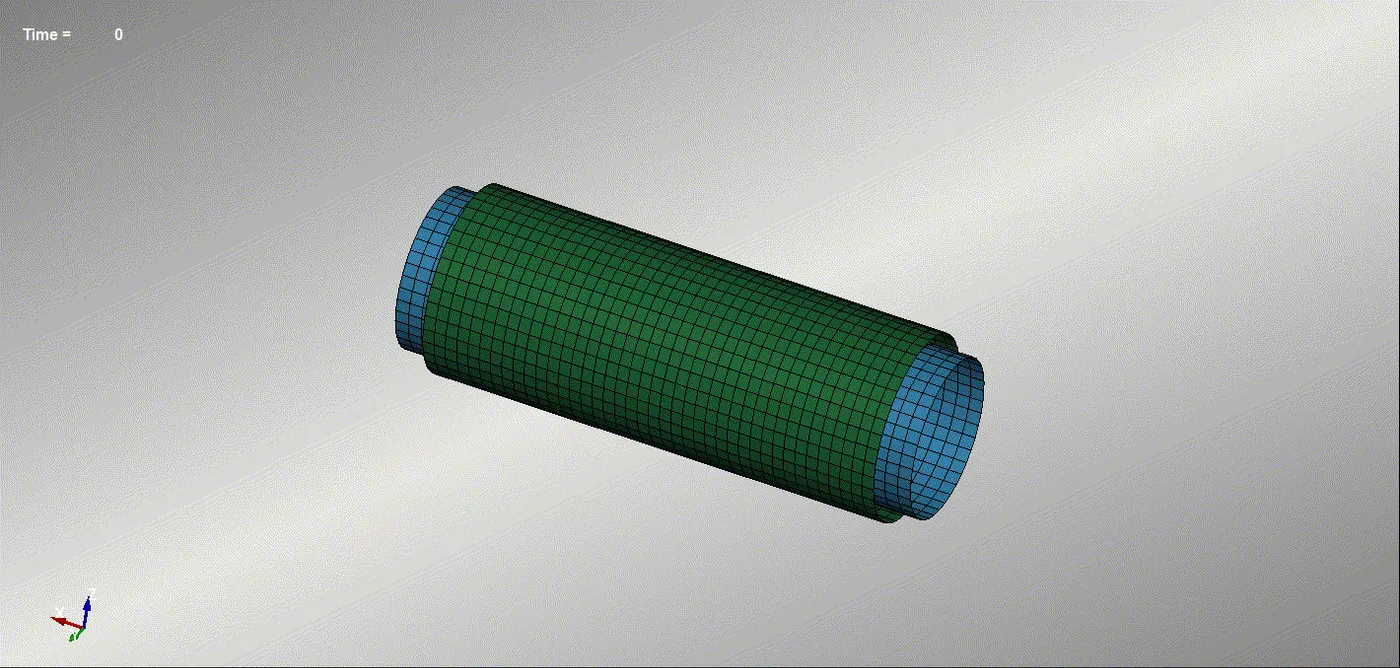
Cylindrical Joint
This is the simplest of all joint.As the name suggest this joint have all rotational degrees of freedom while the translational dof are all arrested.In order to create this we need to create two sphers one is bigger than the other.So that ine is ball and other one is socket like ball and socket joint.The half of the socket is cut off .This model is used to create the spherical joint.
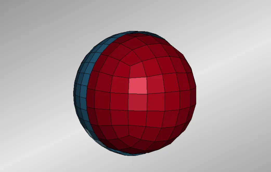
Ball and socket for spherical Joint Creation
Spherical Joint Simulation
We need to create two nodes at thee exact centre of these spheres and then assign one as a part of ball and other one as a part of socket using Constrained extra node set card.(After we assign rigid material to all parts ).Then create the spherical joint using create entity tool using the N1 and N2 as these two nodes.then merge these two nodes.Then assign rotation velocity using Intial Rigid Body card to the ball.
RESULTS
Tranlastional,cylindricak,recolue and spherical joints are created in ls dyna and its working is ensured by running the deck created in Ls Dyna Program Manager.