week-11 Joint creation and Demonstration
G-drive link: https://drive.google.com/drive/u/0/folders/1S18pT4BTUAOJ-_CcfmpdcvvKG5dY2Guq
Simulation video link: https://drive.google.com/drive/u/0/folders/16dxW1p2dg8mwujoqqLEpOK45ycAKQg3g
Aim:
to create the various type of joints based on the ls dyna user guide
1.revoulte joints
2.spherical joints
3.cyclinderical joints
4.transational joints
Case-setup procedure
- part creation
- sec craetion
- mat creation
- RBE creation
- joint creation
- boundary creation
- control creation
- data base creation
Introduction of joints
- A pair is a joint of two elements that permits relative motion.when any two links or elements are connected in such a way that thier relative motion is completely or sucessfully constrained they called kinematic pair
type of kinematic pair
- If a pair in motion has surface contact between the two elements it is called lower pair.such as a sliding pair ,turning pair and screw pairs lower pair
- Ex:Nut and bolt,socket joint
- if a pair in motion has a line or point contact between rtwo elements it is called higher pair
- Ex:cam and fllower
type based on motion
- Sliding pair is when two elements have sliding motion releative to each other it is known sliding pair
- Ex:piston and cylinder
- Rolling pair is when one elemnts is free to roll over other it forms rolling pair
- Ex:a road roller rolling the ground
- Spherical pair one link is constrained to swivel in or about fixed point it forms spherical pair
- EX: a ball and socket
- Turning pair(revoulte) when two elemnts are connected such that one elements revolves around the other.it forms a turning pair
Turning pair(revoulte)
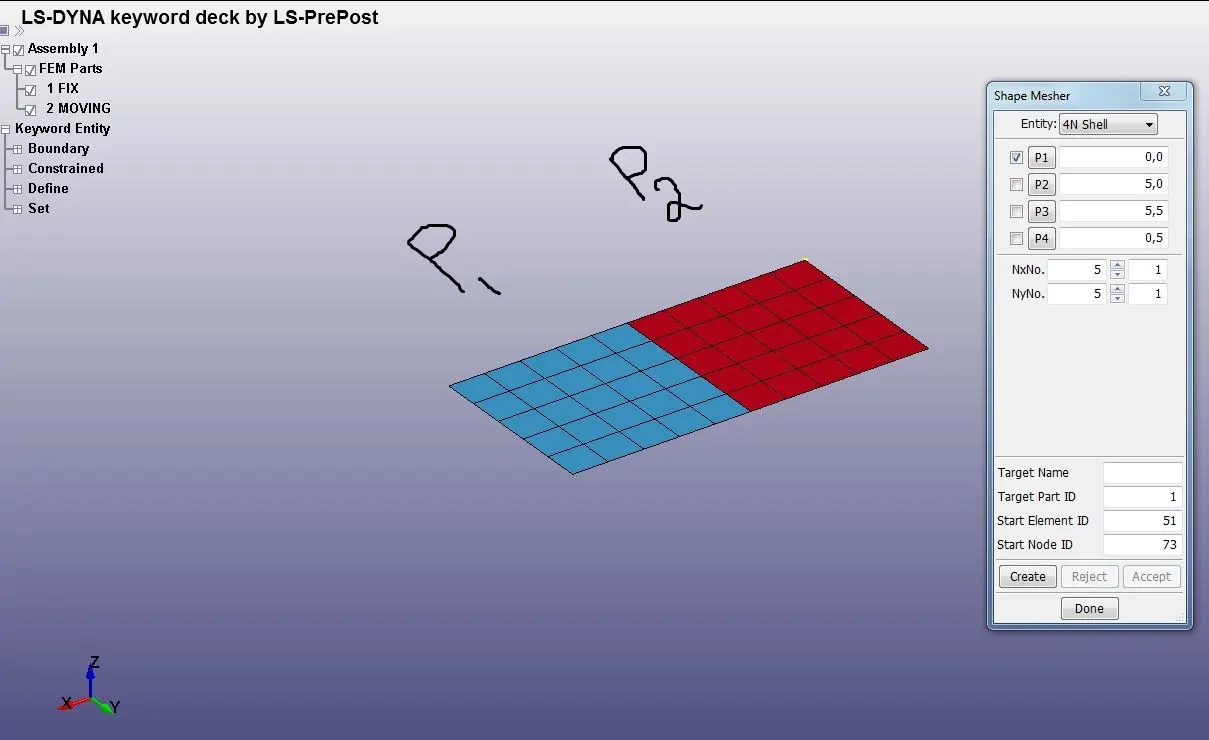
- part creation
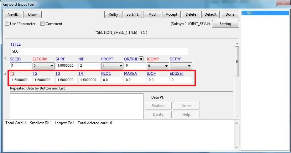
- sec craetion
- here we use the shell plate so, the element section is shell with t=1.5
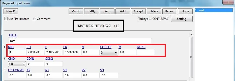
- mat creation
- we using the mat rigid proprty for this joints both fix and moving parts
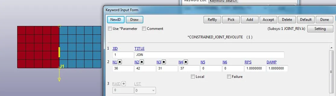
- Joints creation
- In revoulte joint the parts node should be conincident such example p1 havinh 1,2 nodes and p2 having 3,4 means the node number 1,3 and 2,4 should be conincident
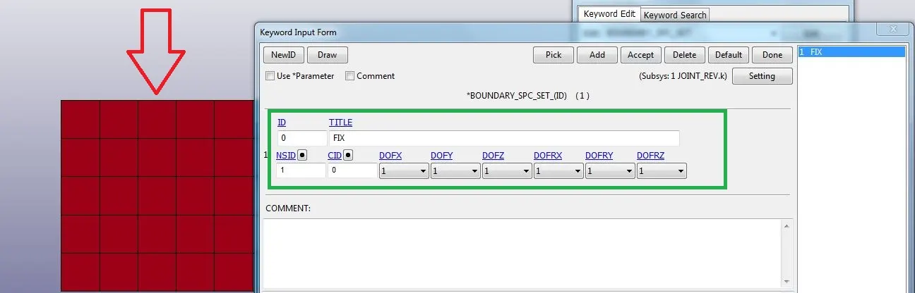
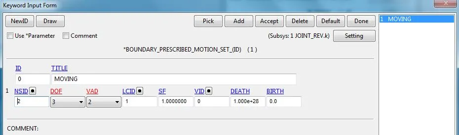
- boundary creation
- While creating the boundary the fix parts is all DOF is completely locked and moving parts id 1DOF translational based on Golbal co-ordinate sysytem
- control creation
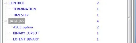
- Basic control and data base cards are added..
Simulation video:
2.spherical joints
- Above same procedure for all but the constraints only may change
RBE creation
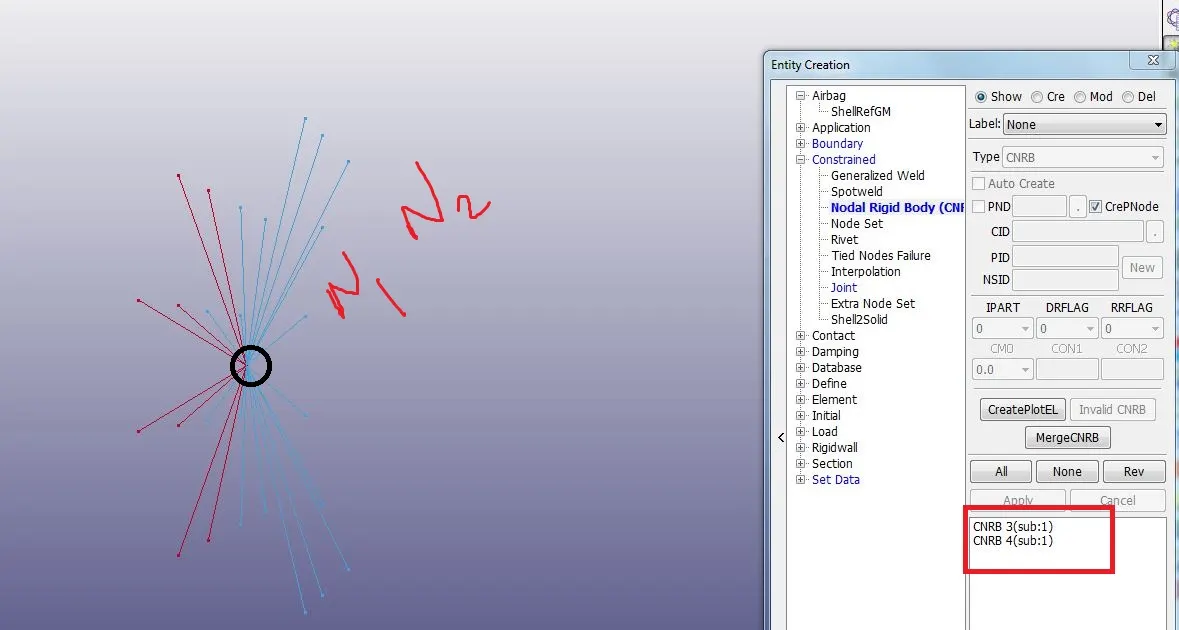
Joints creation
- in spherical join part1 and part2 should be coincedent
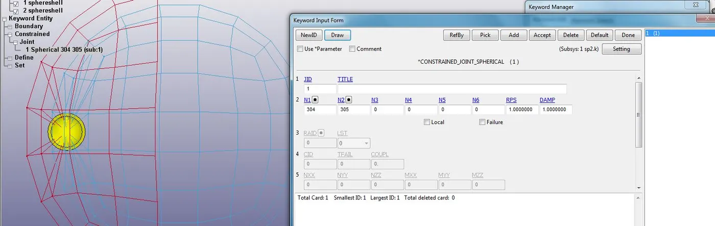
- The node 304 and 305 is part 1&2 conincedent
Simulation video:
3.cyclinderical joints
- Above same procedure for all but the constraints only may change but the joints which allow both rotational and translational
RBE creation
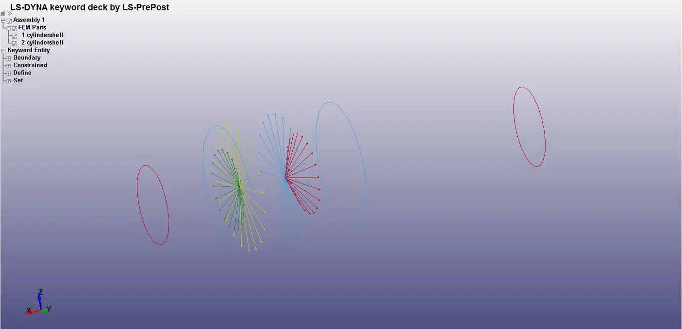
Joints creation
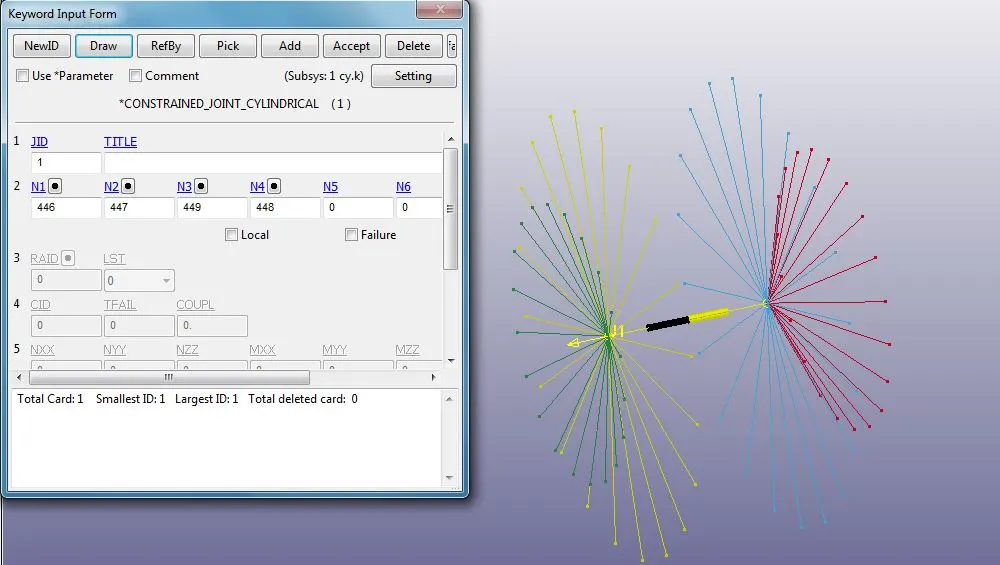
Simulation video:
4.transational joints
- Above same procedure for all but the constraints only may change but the joints which allow translational
RBE creation
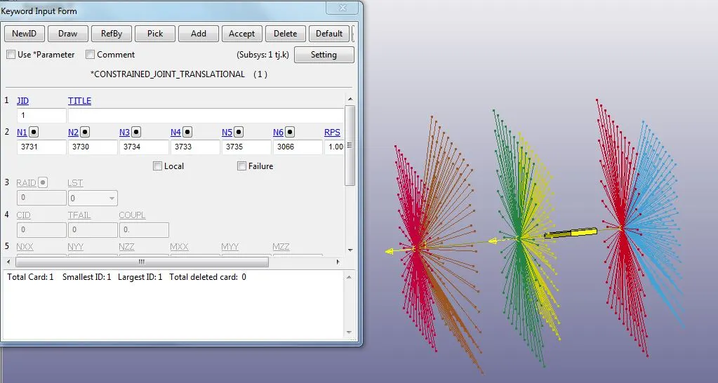
Simulation video:
Conculsion
- in this assignment we learn the various pair of joints and it motion
- we learn the how create the cnrbe node and how to assign node for particular joints