Week 11 - Final project
FINAL PROJECT
AIM:
- To create a door interior part from the inputs of class A surface along with master section by following the design rules followed in tier 1 and OEM industries in catia v5.
GIVEN DATA
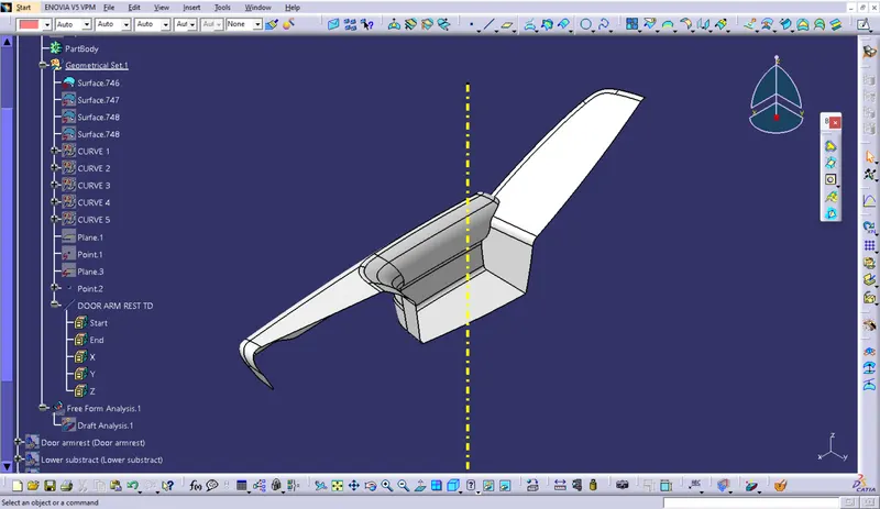
Creating a tooling axis in class A surface:
- The direction in which the mould open and closes is the tooling axis.
- Check the connectivity of the surface and ensure there will be no gap between the surfaces and then define the tooling axis.
- While creating a tooling axis give the tooling axis on a flat length surface or the surface which have a hole on it.
- Create a point on the surface where we are going to create the dummy tooling axis and using line command crate an axis. If there is a circle or flat length surface which is recommended.
Draft Analysis:
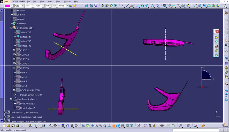
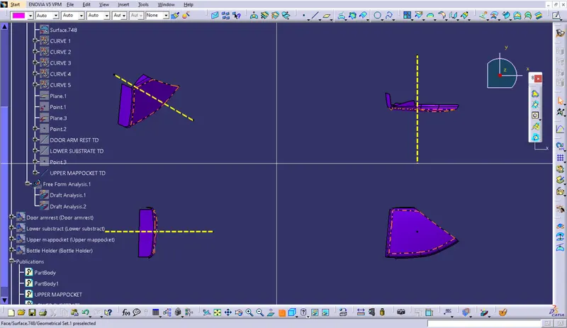
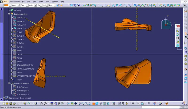
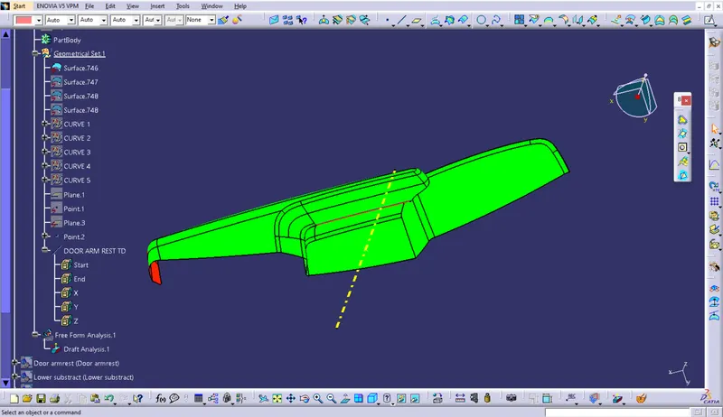
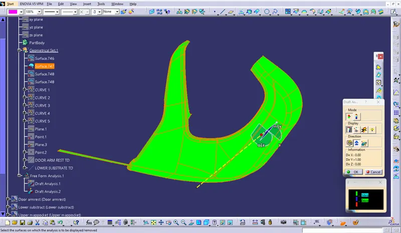
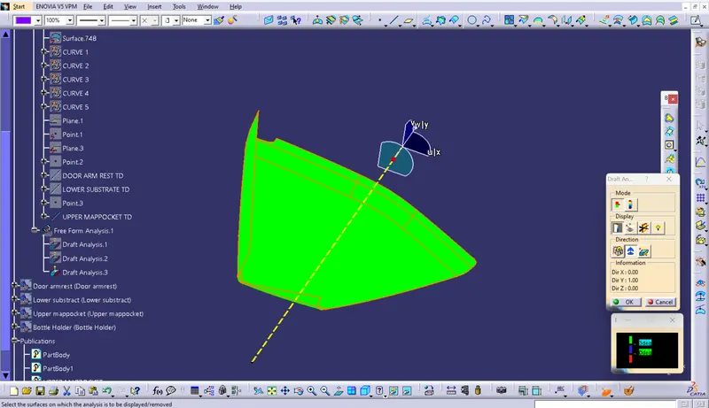
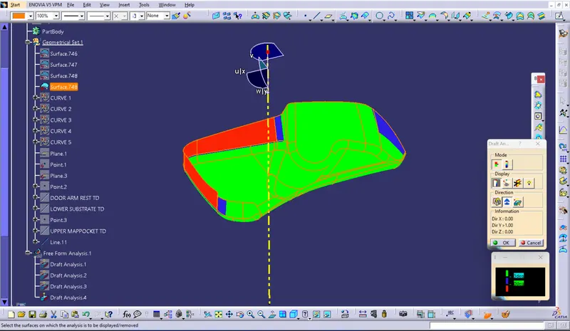
- The draft analysis technique is used to analyze whether our part model created in CAD is manufacturable based on the draft condition applied.
- Minimum draft angle is considered as 3 degree.
- step 1= enter part in Catia.
- step 2= Go to Material Mode.
- step 3= go for draft analysis.
- step 4= drag axis bar to the tooling direction of part.
- step 5= check for draft and make parting line as per analysis.
Create a class B surface:
- Class B surfaces are the secondary surfaces in plastic component design.
- In this model Class B-Surface is extracted from the A-surface and it is offseted at 2.5mm in downward direction.
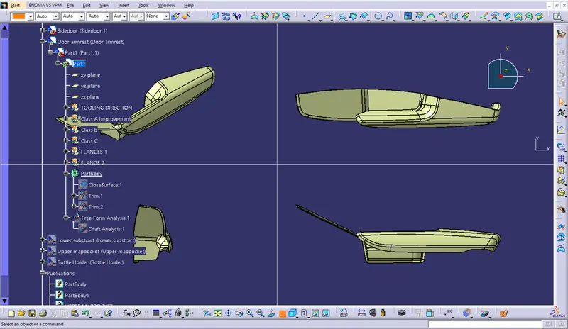
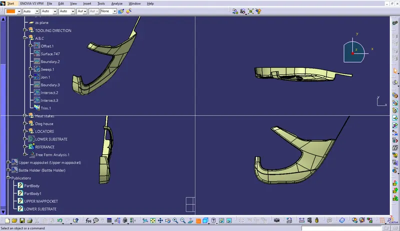
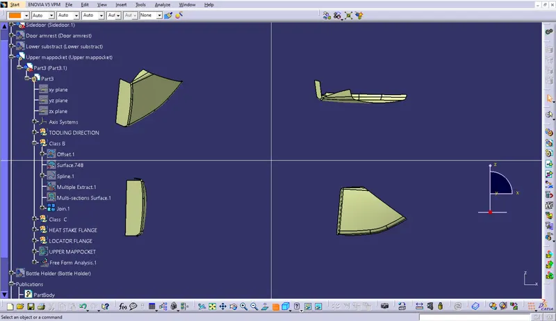
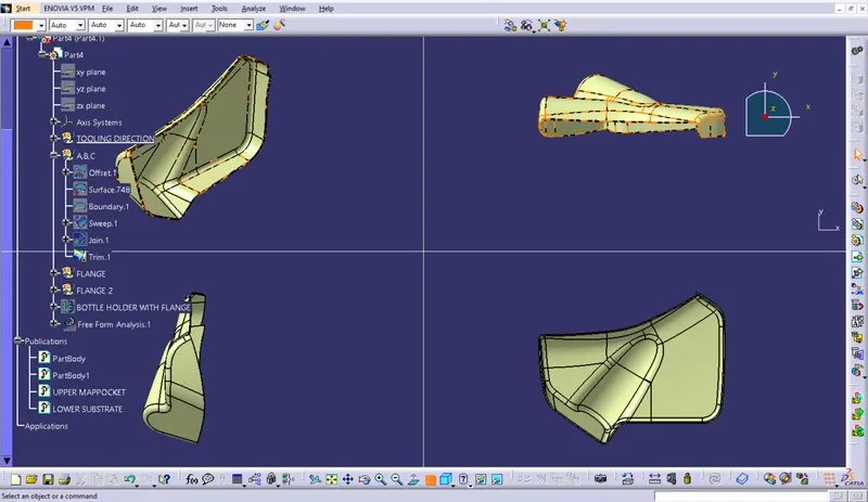
create a class C surface.
- Class C is often specified for interior surfaces not readily visible, surfaces that will be covered by another part when assembled, or surfaces which the Customer feels do not need to meet a high cosmetic finish.
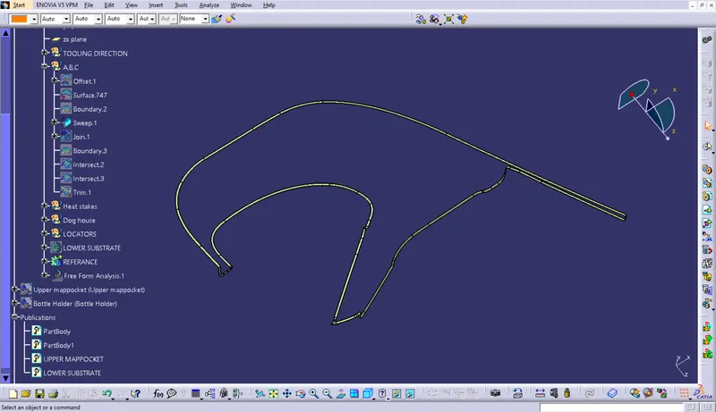
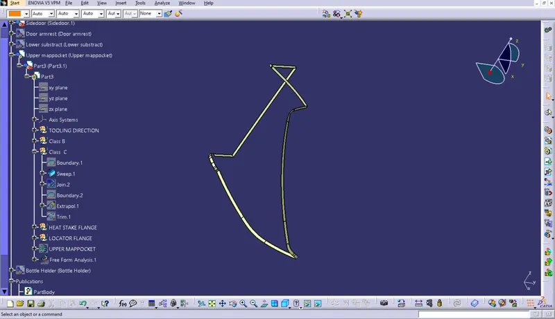
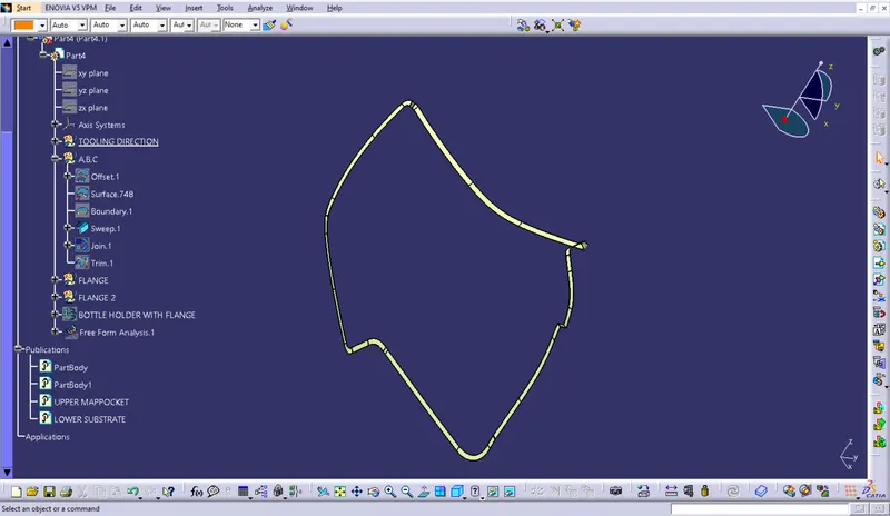
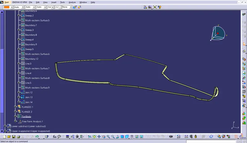
- C-Surface connects the class A-Surface and B-Surface. It is created using Sweep command.
- Boundry of the class A-Surface is swept along the tooling direction.
DOG HOUSE
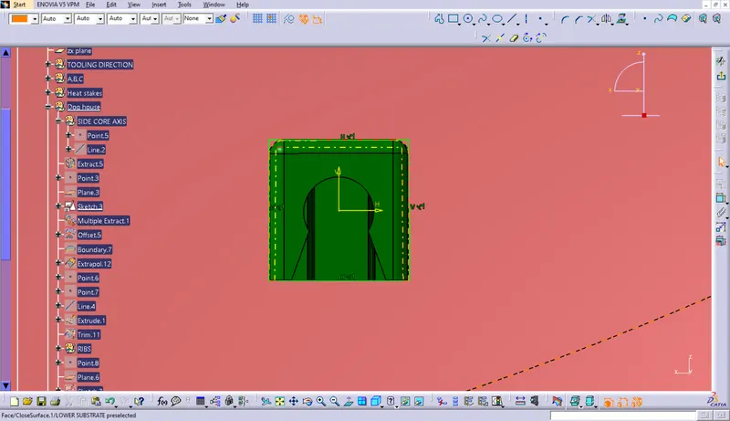
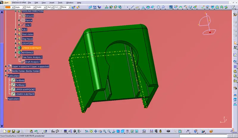
- Dog house is an engineering feature used in plastic trim design. Dog houses are used as supporting feature. Sometimes other engineering features like snaps; locators etc. are mounded on them to increase their strength.
- Dog houses are subjected to draft analysis to prevent breakage of the component during ejection from mould cavity. Dog house and other engineering components are built on B-surface.
- Thick sections waste material and are simply uneconomic. So solid shapes that would do the job well in wood or metal must be transformed to a 'shell' form in plastics.
- Tooling must be cleared for easy ejection of the component, from the core cavity. In order to clear tooling certain value of draft is given to the component. Minimum of 2-3deg is provides on all plastic components.
LOCATORS
- Extract the surface that we going to create locator
- Use positiioned sketch and draw a locator sketch
- Use pad commands for the sketch to till we required
- Draft the locator for minimum of 0.5 degree
- Add fillet 0.5mm o all faces
- Assemble the locator to lower subtrate solid
- Maintain a 50mm minimum between two locator
- Translate the locator to wherever we need
- Trim the all heat stakes with lowersubstrate solid
- Maintian a height more than heat stake
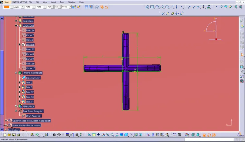
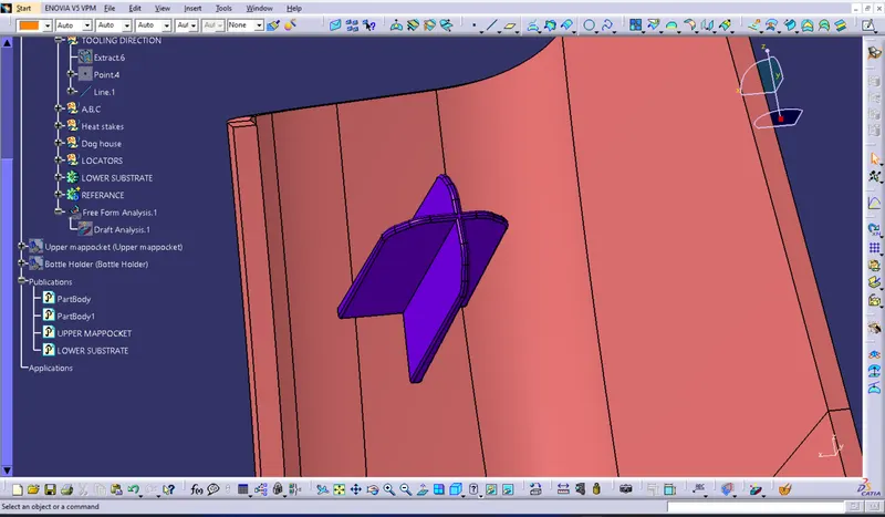
Sketch Plane is made in the tooling axis direction.
Height = 20 mm
Wall Thickness = 1.3 mm
Draft Angle = 0.5°
Chamfer = 3 mm, 45°
Fillet 0.3 mm & 3 mm
HEAT STAKES
Heatstakes is known as thermoplastic staking is the process of joining two dissimilar metals together
- Extract the surface that we going to create heat stake
- Use positiioned sketch and draw a heat stakes sketch
- Use pad commands for the sketch to till we required
- Draft the stakes minimum of 0.5 degree
- Add fillet 0.5mm o all faces
- Assemble the heat stake to lower subtrate solid
- Maintain a 50mm minimum between two heat stakes
- Translate the heatstakes to wherever we need
- Trim the all heat stakes with lowersubstrate solid
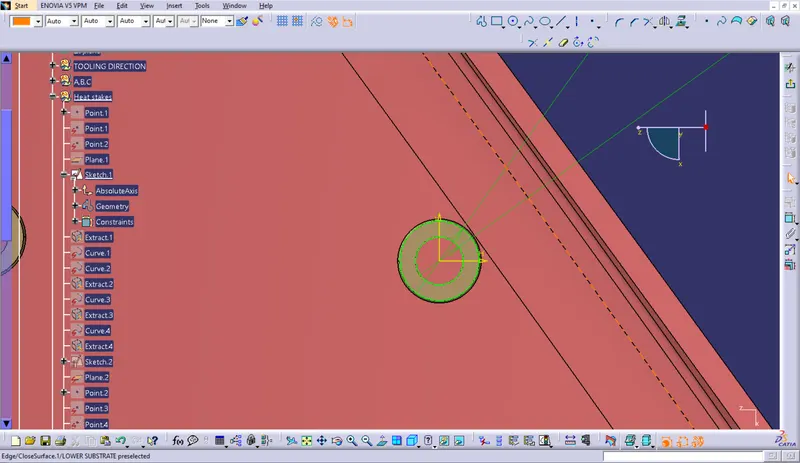
Sketch Plane is made in the tooling axis direction.
The length of heat stakes should be at least 5 mm lesser than locators, L = 15mm
Radius, ID = 5mm, OD = 7 mm
Draft Angle = 0.5°
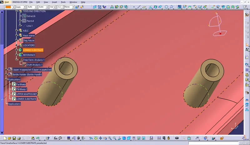
FLANGE
Create a flange for attachment of heatstakes and locators at lower substrate.
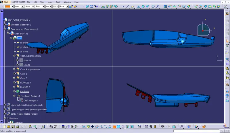
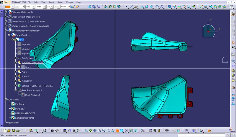
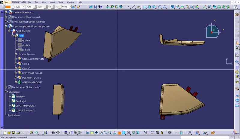
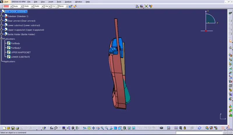
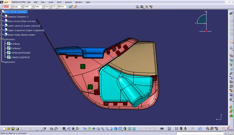
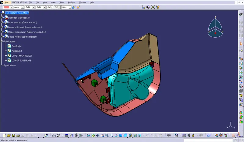
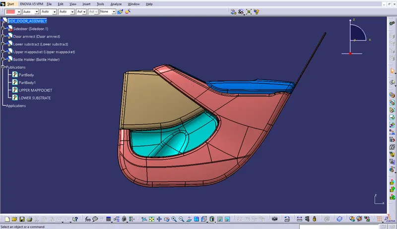
FINAL PART BODY
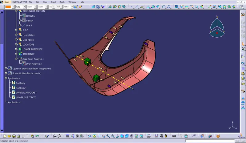
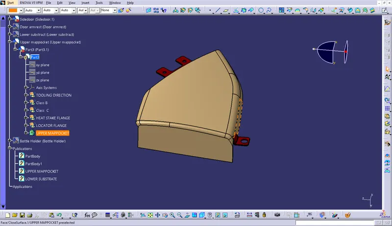
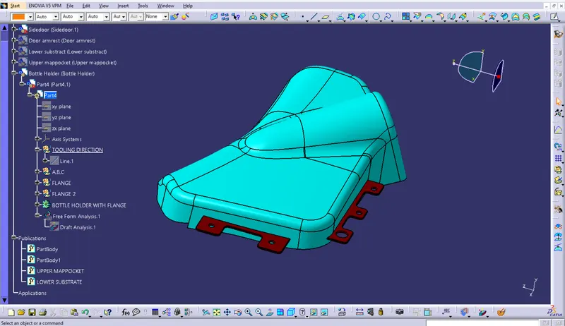
FINAL DRAFT ANALYSIS
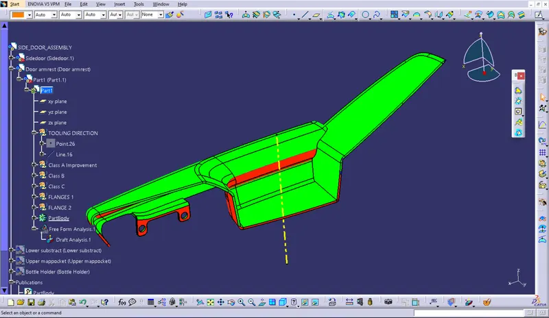
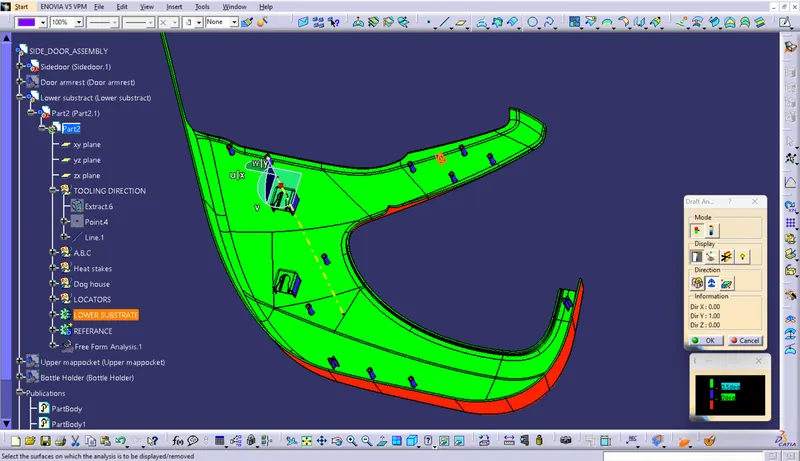
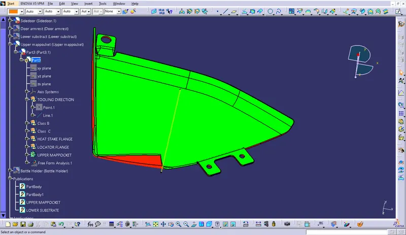
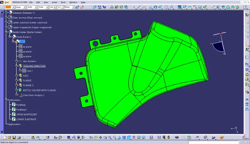
FINAL OUTPUT