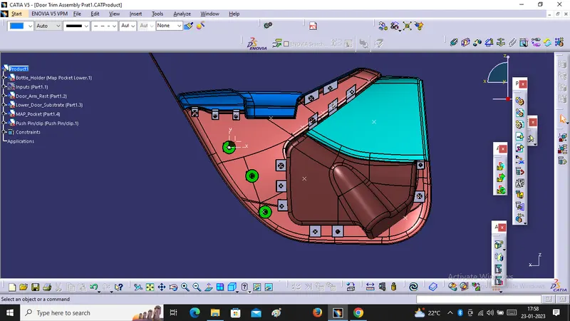
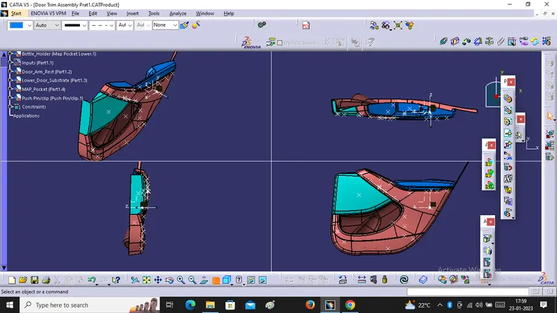
Week 11 - Final project
Objective :
. To create a close Body of the Door Trim panel using the class-A surface Provided with master Section.
. To create pushpin with the Doghouse for the lower substrate.
. To create Heatstake for the part attachment.
Introduction:
Door Trim panel is an interior component attached to the inner side of the door. Besides it is asthetic look, it is also has many functional features such as an Door Arm rest, Map Pocket, Bottle Holder, Lower Door Substrate.Door Trim panels are often made of Acryonitrile Butadiene- Styerene (ABS), Polypropylene (PP), Polycarbonates, Polyvinyl chloride (PVC), Modified Polyphenylene Ether (PPE) and Styrene- Maleic anhydride (SMA).
Approach for devloping the Door trim panel :-
. Extract the required portion of class-A and modify it, if required.
. Creating Tooling Axis.
. Perform Draft analysis on the class-A surface.
. Create class-B Surface.
. Join Class A & C surface and trim it along class-B surface.
. Finally, We get the Surface body of that portion which can be made as a Solid Component using the 'close surface' option.
. Creation of B-side features.
. Perform Draft analysis on final solid component.
1. Map Pocket:
Draft Analysis & Tooling Axis Creation For class A :-
For Tooling Axis we will Extract one surface create one point on surface it after that create one line on point & Direction method . After, that we will do Draft Analysis for class A surface with Tooling Axis.

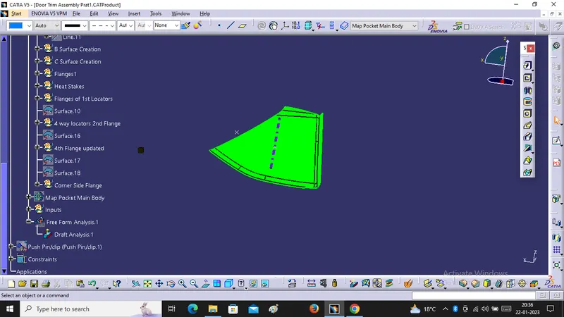
B Surface Creation :-
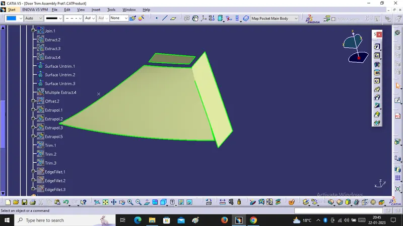
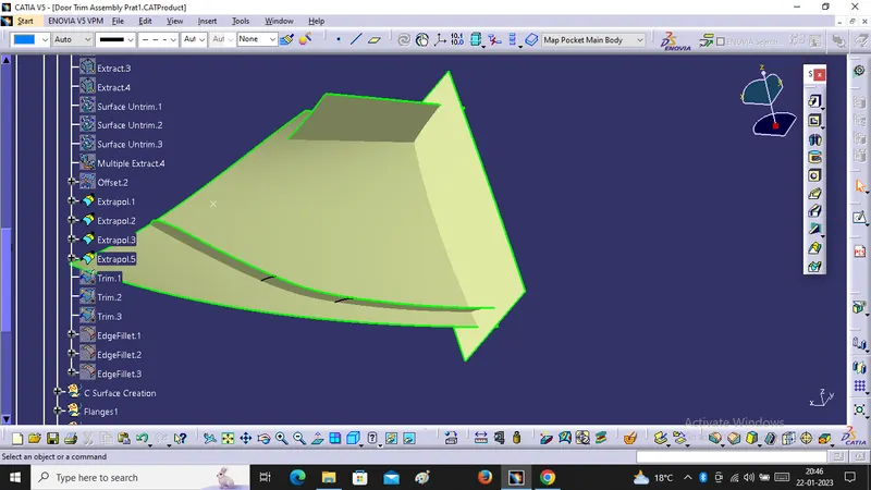
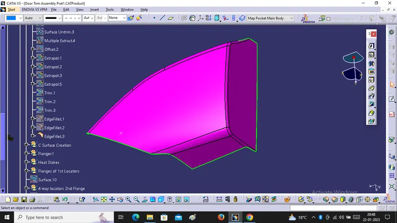
For B surface creation we will offset class A surface for 2.5 mm in Inside direction after that we will get patch up area surface , and we will remove that patch up area by using multiple extract, surface untrim, Trim, Offset, Extrapolation, Edge Fillet and get Final B Surface.
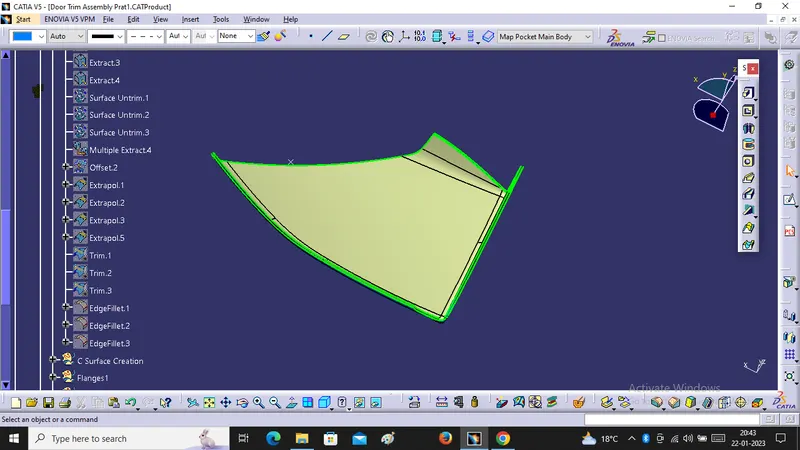
Surface Untrim :
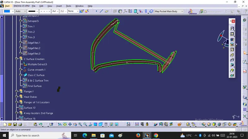
C Surface Creation :-
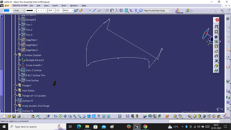
For c Surface Creation we will using Multiple Extract, Smooth Curve & Sweep after that we will get C Surface. We Will Take Reference from Class A Surface.
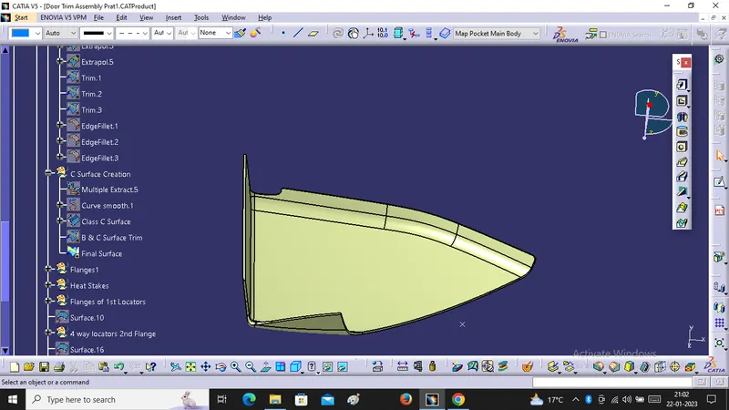
Final Surface :-
For Final Surface Creation, We will Trim Class B with C Surface , after that we will Trim class A Surface with B & C surface Trim. After, that we will get Final B Surface.
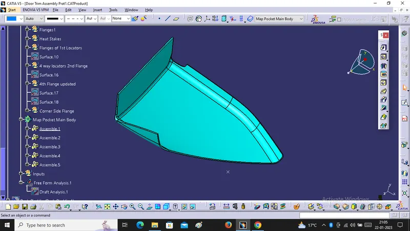
Close Surface :-
For close surface Creation we will use close surface in part design and choose final Trim.
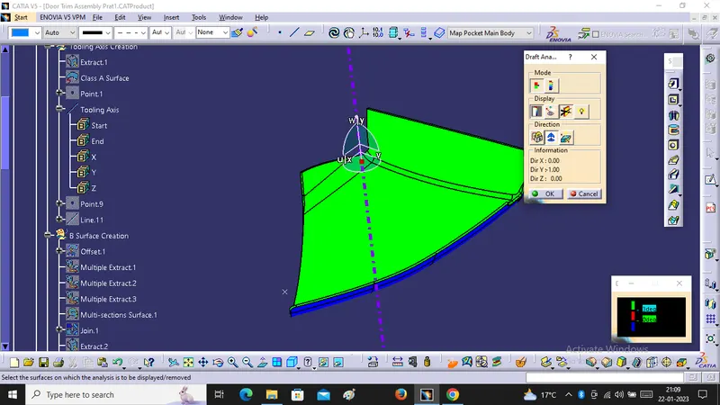
Draft Analysis for Close Surface :-
After that we will use draft analysis for close surface at 3 deg with Main Tooling Axis.
Bottle Holder :-
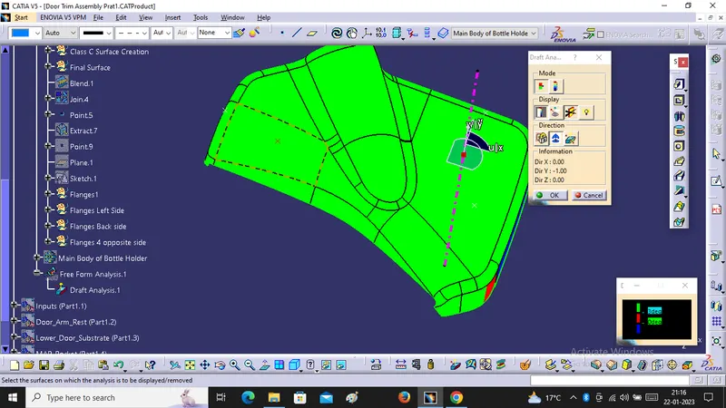
Draft Analysis & Tooling Axis Creation for class A surface :-
We will Extract one Surface from Class A Surface create one point by point on Surface and one line by point & Direction method after that we will do draft analysis with given class A surface at 3 Deg.
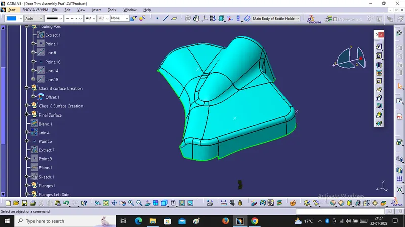
Class B Surface Creation :-
For B surface Creation we will Offset it for 2.5 mm in inside direction , after that we will get same as class A surface . That is our B Surface.
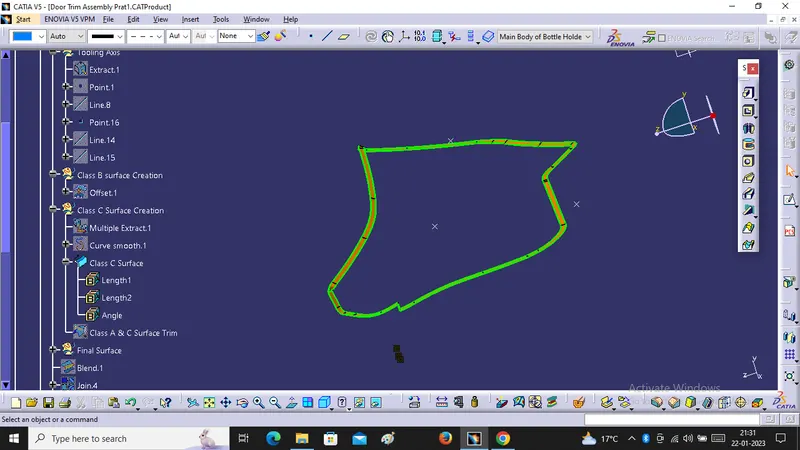
Class C Surface creation :-
For c Surface Creation we will using Multiple Extract, Smmoth Curve , Sweep with reference of class A Surface and we will get C Surface.
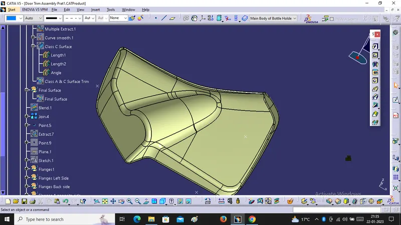
Final Surface :-
For final Surface Creation We will Trim A & C Surface after that we will Trim with B Surface We will get Final Surface.
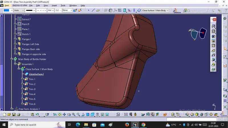
Close Surface :-
We will go into the part design, and Convert our final Trim Surface into Close Surface.
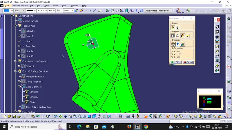
Draft Analysis For Close Surface :-
After that we will do Draft Analysis for close Surface at 3 deg.
Door Arm Rest :-
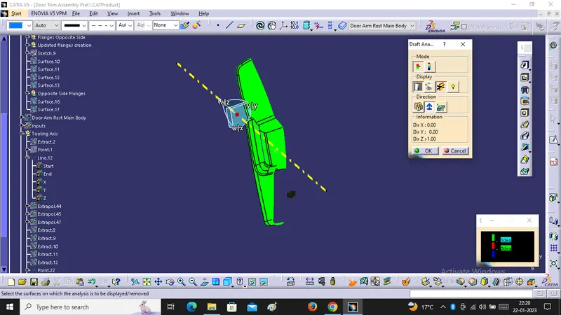
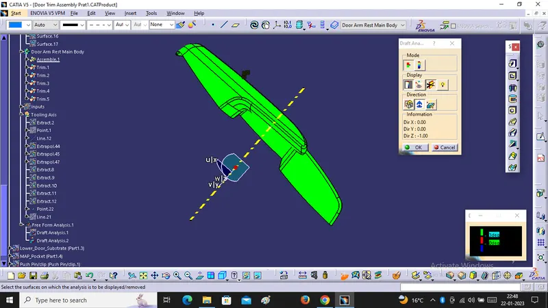
Draft Analysis & Tooling Axis Creation for Class A Surface :-
We will Extract one Surface from Class A Surface create one point by point on Surface and one line by point & Direction method after that we will do draft analysis with given class A surface at 3 Deg.
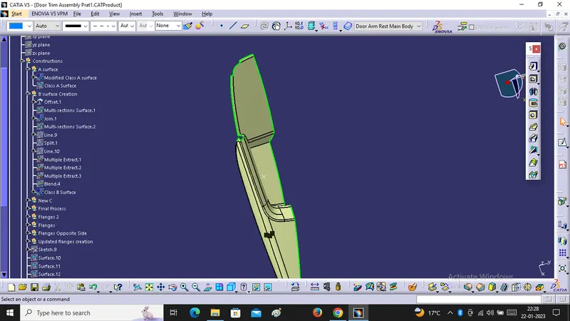
B Surface Creation :-
For B Surface Creation, We will offset class A surface for 2.5mm in inside direction after that we will get patch up surface and we will repair the surface by using Multiple Extract, Multi Section Surface, Join after that we will get final B Surface.
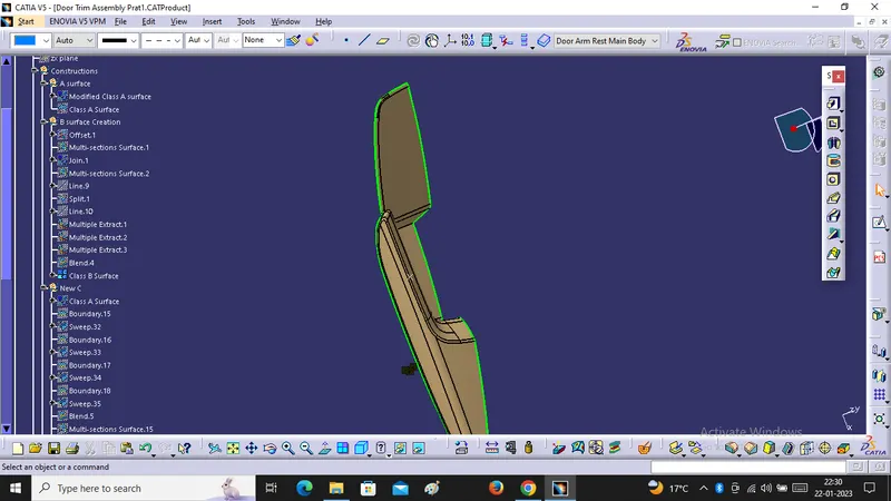
Class C Surface Creation :-
For c surface Creation We will Take Boundary Part By Part and Create Sweep With Reference Surface A and we will Join all the Sweep Surface We will get Final C Surface.
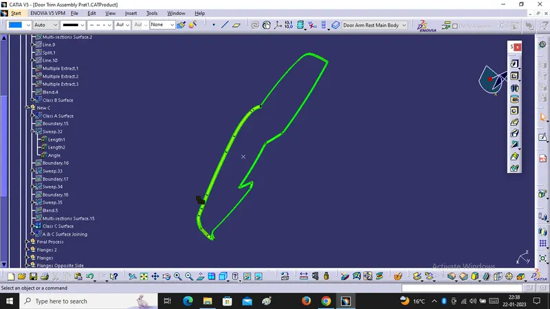
Final Surface Creation :-
For Final Surface we Will Join A & C Surface after that we will Trim with B Surface we will get Final Surface.
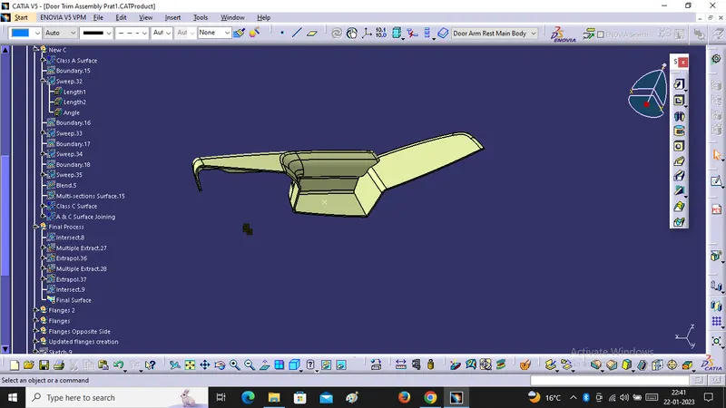
Close Surface :-
For Close Surface we will go to Part Design and select the Final Trim Surface and Convert it into Close Surface.
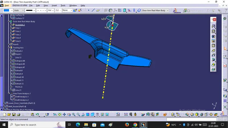
Draft Analysis For Close Surface :-
After that we will do draft Analysis for close surface at 3 deg.
Lower Door Substrate :-
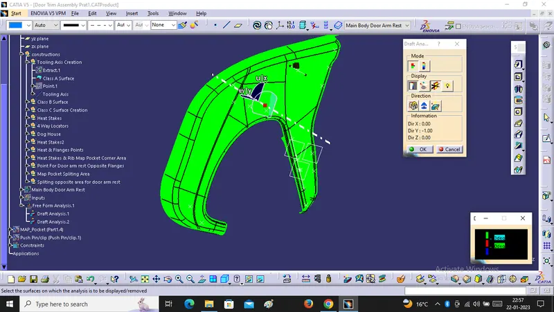
Draft Analysis & Tooling Axis Creation for Class A Surface :-
We will Extract one Surface from Class A Surface create one point by point on Surface and one line by point & Direction method after that we will do draft analysis with given class A surface at 3 Deg.
 w
w
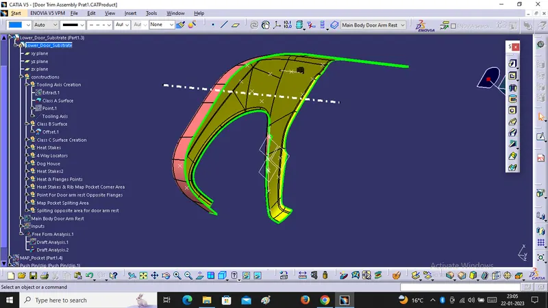
B Surface Creation :-
For B Surface Creation we will Offset Class A Surface for 2.5 mm in inside direction we will get B Surface with no patch up Area. So this is our Final B Surface.
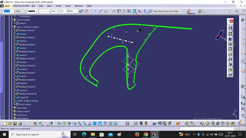
C Surface Creation :-
we will create C Surface by taking Boundries and Create Sweep for it after that we will Join all the Sweep together and we will get C Surface.
Final Surface :-
For Final Surface Creation We will Join A & C Surface after that we will Trim with B Surface, We will get Final Surface.
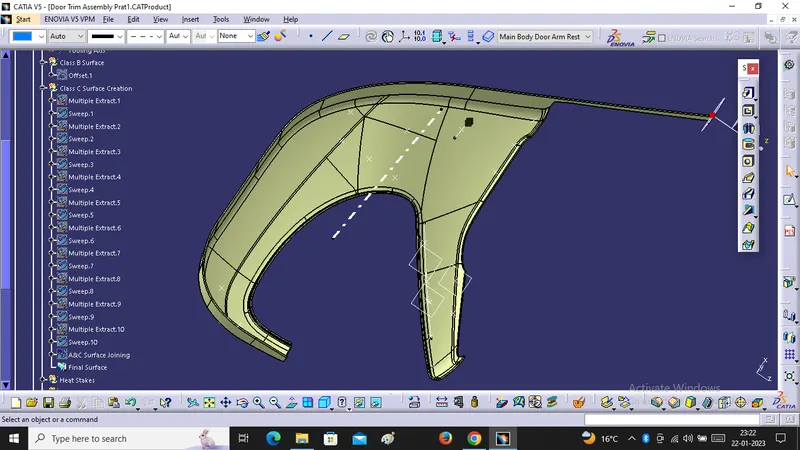
Close Surface :-
After that we will go to the part Design and Convert the final Surface into the close Surface.
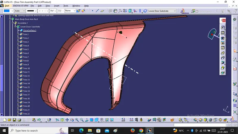
Draft Analysis for Close Surface :-
After that we will do Draft Analysis for Close Surface at 3 Deg.
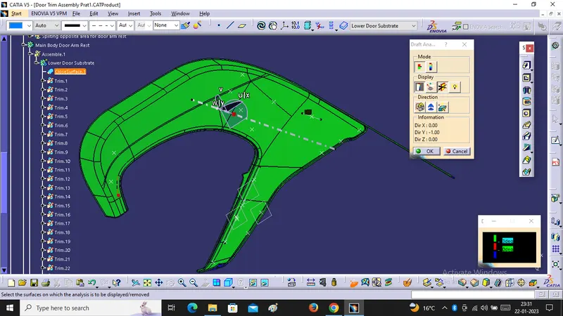
Engineering Features Creation Lower Door Substrate :-
We will Create Enginnering Features On B side of Lower Substrate to give Support to the Surface.
Dog House :-
Dog House is an Engineering feature used as Supporting feature for B Side Surface. The Primary function of Dog House is to avoid Sinkmarks.
Steps For Creation of Dog House :-
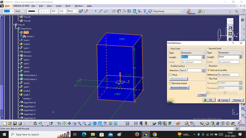
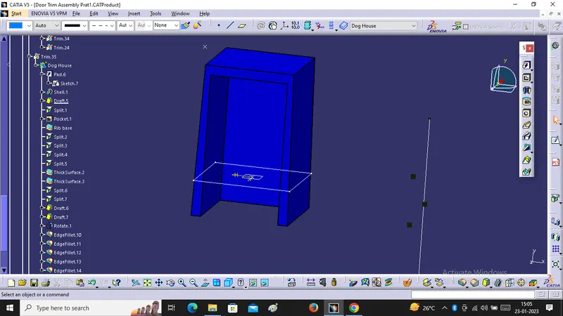
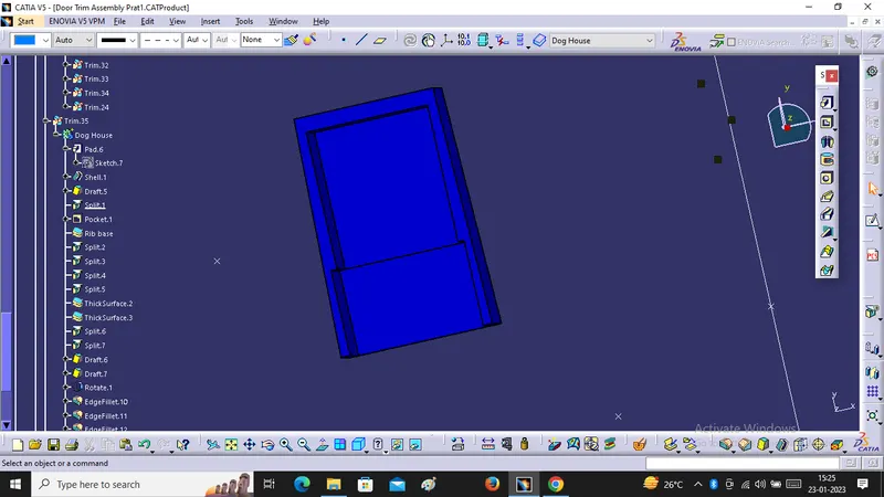
Firstly we take one point on Surface and Create Sketch of center Rectangle of 25mm and pad it for 30 mm and shell it for 2.5 mm after that we will get the Dog House Main Body after that we will do drafted it for 1.5mm of outer Wall with Main Tolling Axis.
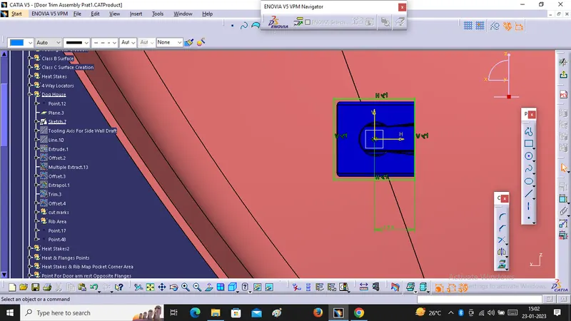
Rib Area :-
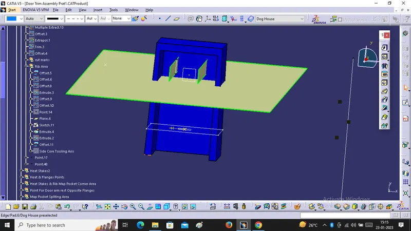
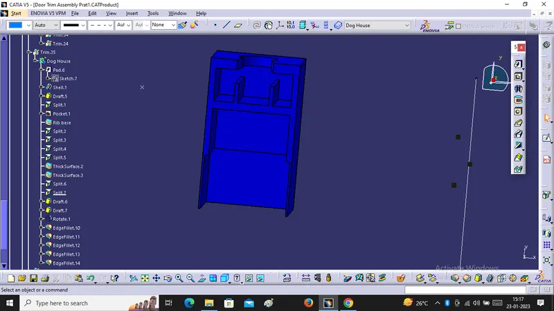
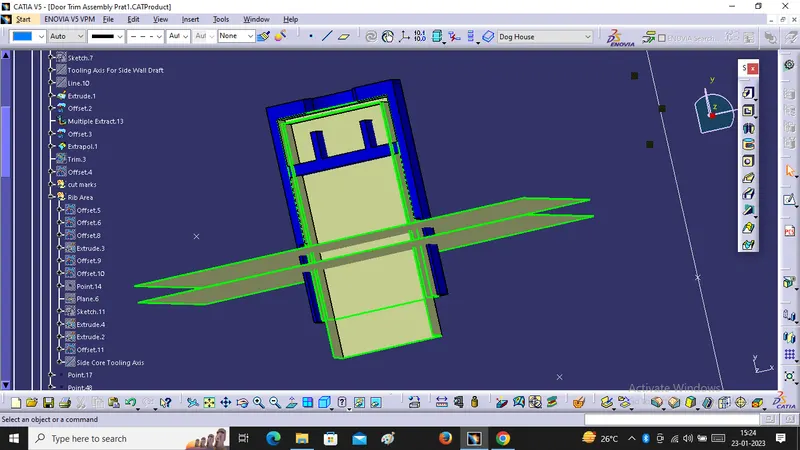
For Rib Creation We Create One line on Bottom Side Extrude it and offset it for 17.5 mm take one point on Curve take offset one plane from point Create Sketch and Extude it after that apply thickness and Split the Unwanted Surface.
C Undercut Area Of Doghouse :-
For c Surface Creation We will Extract Intenal Face and offset it for 1mm and also the base surface for 3to6 mm, after that we will trim it and get one Surface , after that we Split Solid Body with Trim Surface.
Cut Marks On Upper Surface :-
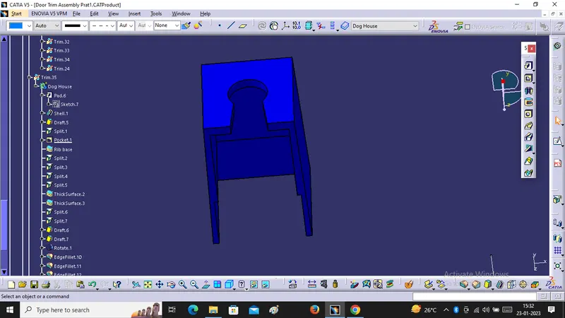
We will take one point on Surface and offset one plane on that Point create sketch and pocket it for 2.5mm we will get the Cut Marks.
Draft Analysis On Side Wall :-
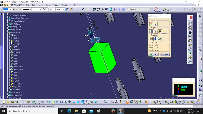
We will give 1.5 degree draft to the Side wall of Dog House with main Tooling Axis.
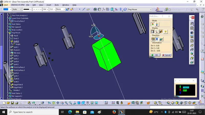
Side Core Axis :-
Here Side Core Axis is Creates along Z axis because the Dog House Face Opening along Z axis. That is Created a line On Point & Direction metods. This is probably used by giving Draft to Intenal Faces of Dog House.
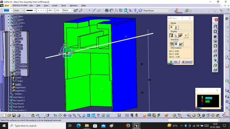
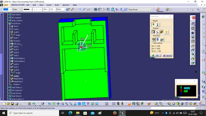
Edge Fillets :-
we have to minimum Edge fillets to dog House Internal Edges and 1mm to External Edges.
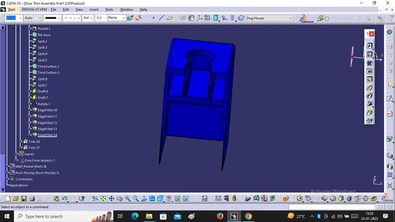
Heat Stakes & Rib Creation :-
Heat Stakes is Prefered to joining metal Parts to plastics . It is also used to join two dissimlar Plastic Components.
Steps for Heat Stakes Creation :-
We will take one Point and Plane on it create Sketch of Two Circles Dia 5mm & 7mm , after that pad it for 22 mm and giving draft to internal face and external face for 0.5 degree. and give minimum fillet of 0.30mm.
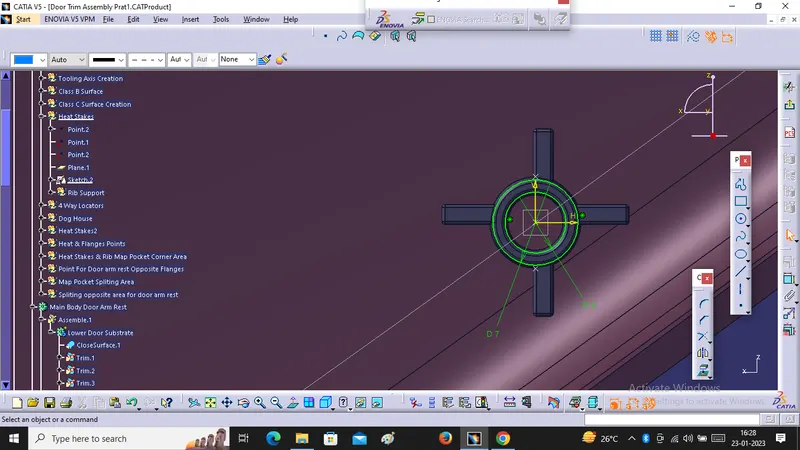
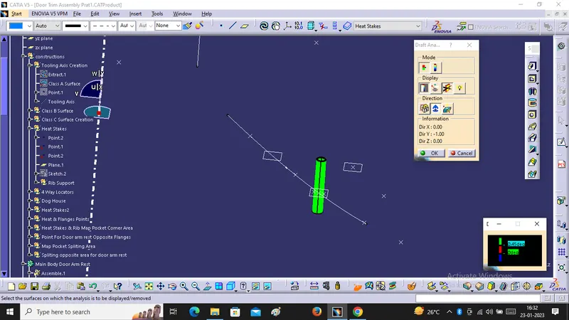
Draft Analysis of Heat Stakes :-
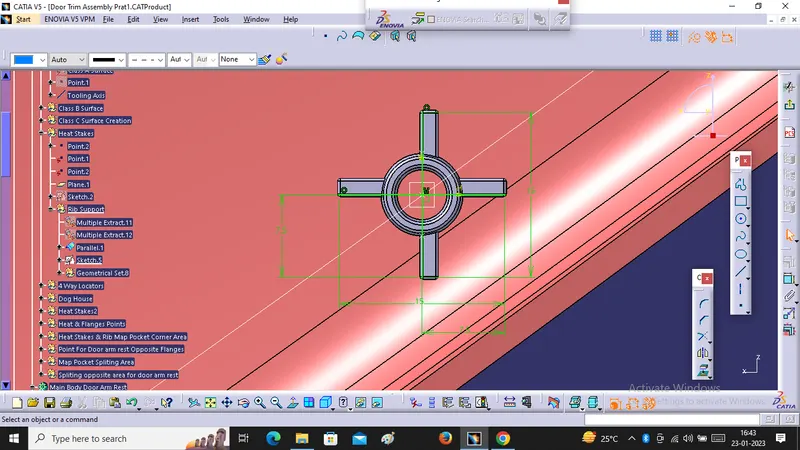
Rib Support for Heat Stakes :-
Ribs are Used to give rigidity and Support to Heat Stakes. Its Height Should be 5mm or more less than Heat stakes. For this we are using Point and plane create Sketch and Pad it Giving Draft of 0.5mm . and mininum edge fillets.
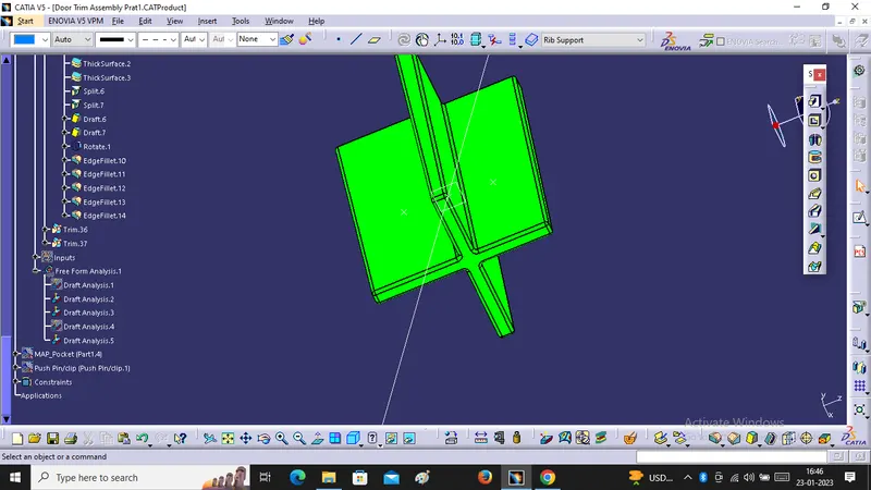
Draft Analyis Of Rib Support :-
Holes & Flanges creation :-
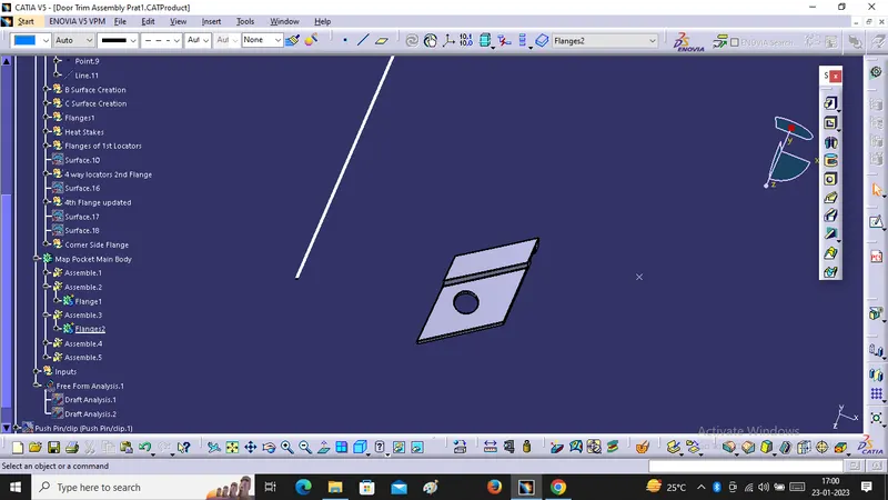
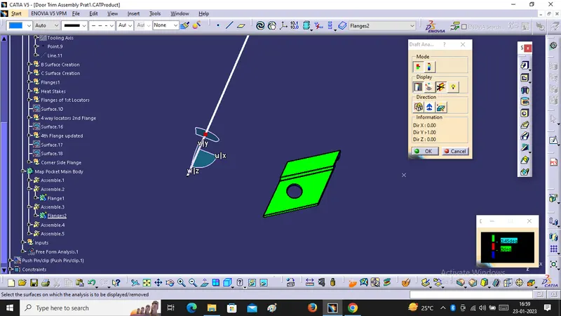
The Door Trim Assembly has to be rigidly fixed as One Unit . The 4 Components will be Permanently arrested to the Lowered Substrate by using the Heatstakes. The Heatstakes will pass through the flanges of components, therefore some clearance of 1mm has to be Provided.
We have to create Flanges with reference of c surface , and give thickness of 0.25 mm and draft of 0.5mm after that minimum fillet to all the sharp Edges.
4 way & 2 Way Locators :-
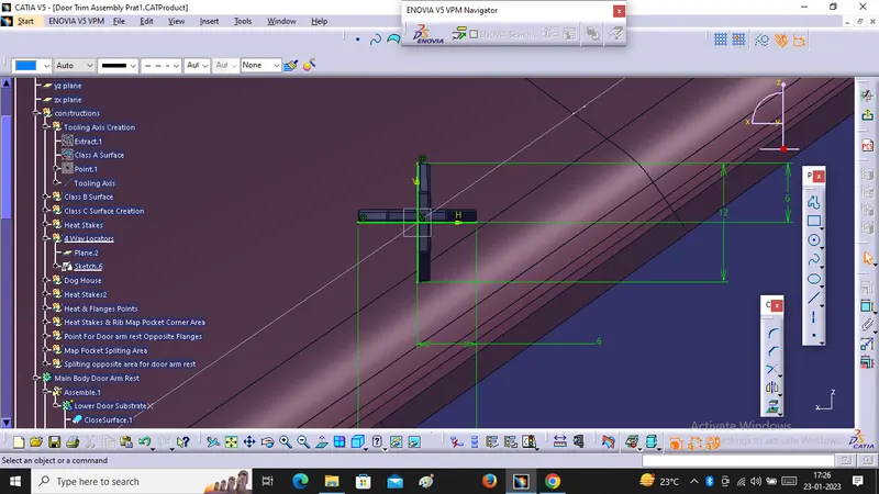
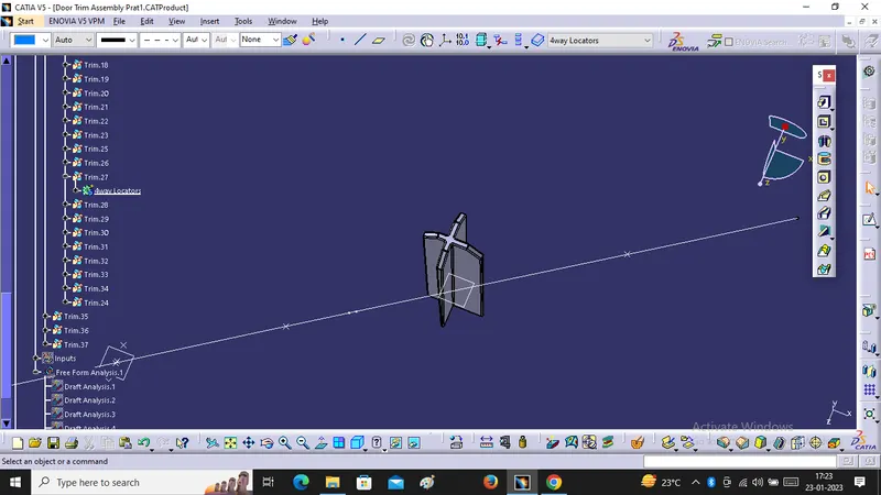
Locaters are generally used to restrict the motion and support the B side surface and features.
For four way locaters take one point and plane create sketch on it pad it given draft of 0.5 degree for all faces, chamfer it for 3 mm and 45 degree giving minimum fillets of 0.30mm. Its Height Should be more than Heat Stakes 3 or 5mm.
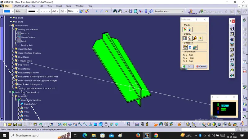
Draft Analysis for Four Way Locators :-
Translation Of Plastic Features and Boolean operation (Union Trim ) :-
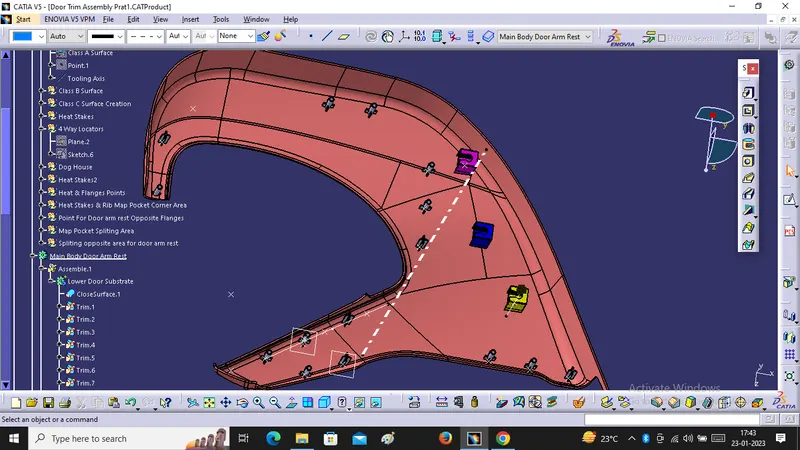
After creating a Single Feature , we can translate it to the desired location. First copy the respective features part Body into the main part file copy , Paste Special as specified in part document this removes the parent- children relationship and we can edit the translated part according to our needs. we need to add all the translated features to the main body of the substrate. The Union Trim Operation fit the Best option for our needs . Define the Main Part body as the working object select Feature Body > Union Trim > select Faces to remove/ keep.
Pushpins :-
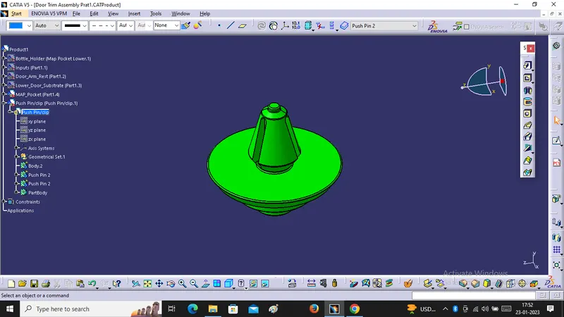
Pushpin which helps us in Locating and Arresting components of an Assembly and it Provides Alignment in Mating Parts and it also acts as a stopper or guide for various mechanisms. we will placed it on the cut Marks of Dog House.
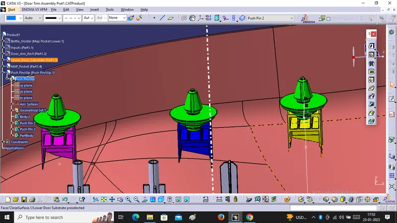
Final Assembly Images :-