Week 11 - Final project
AIM : Development of a Door Trim panel
OBJECTIVE :
Create of CAD model considering following inputs as like in OEM and tier1 companies
- a) Class A surface
- b) Nominal thickness : Refer master sections
- c) Attachment strategy :
Find a attachment strategy for the door panel complete work.
Use Push pin with Dog house for Lower substrate – Door panel attachment
Use heat stakes for part to part attachment
Output required:
- Create thickened part using master section for reference
- Create the mounting features as per design guidelines in the industry and with master sections
- Apply material details :
- Draft analysis & Tooling analysis
- Creation of parting lines and check tooling feasibility
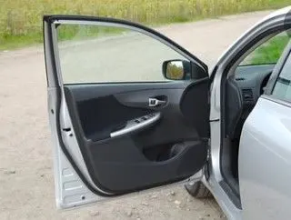
Normal car door for referance
MASTER SECTION
The given file opened in the catia and it have both class a and master section
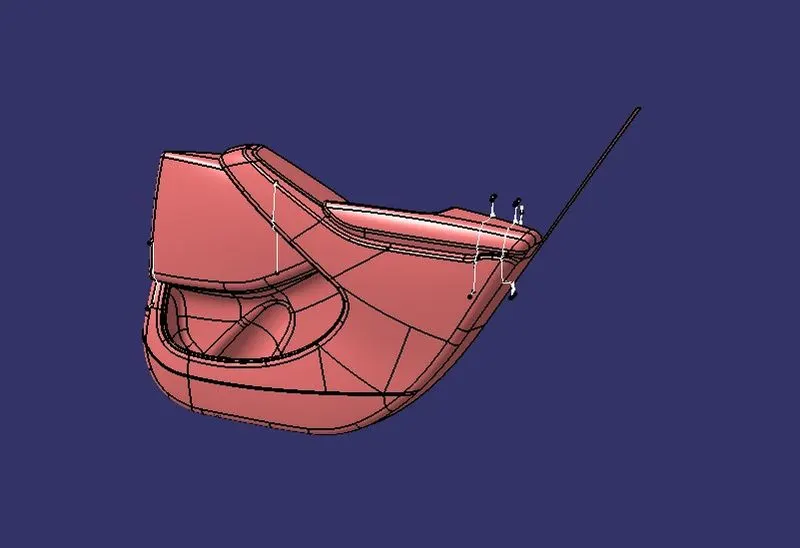
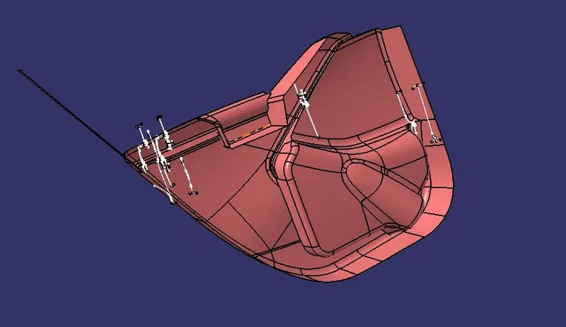
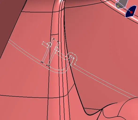
2.CREATION OF TOOLIONG AXIS
The assembly contain 4 part select one part and make the tooling axis accordingly
1. ARM REST
Since the created tooling axis does not clear the draft analysis at the created axis , click on the lock axis button to unlock it . Now rotate the tooling axis by left clicking on the top round portion of the axis system . Rotate the axis till maximum clearance is obtained . Now right click on the axis and click lock current axis .
Create a line using the initial axis origin and this axis using point and direction (using compass direction) option . This is our required tooling axis .
Now if we check for draft analysis, we can observe that the ribbed area has not yet cleared draft analyisis. Hence we need to create a side core tooling axis . To do this , create a line using point and direction option with Y direction .
Repeat steps 1 to 5 to ensure the remaing portion which was not cleared using Tooling axis has been cleared using this axis .

Similarly created tooling axis using same procedures to create side core axis
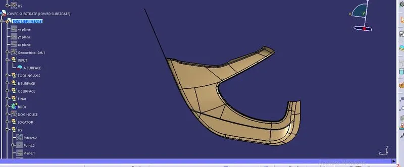
2. Lower substrate
For lower substrate tooling axis creationj we can do the normal to plane method
Procedure to check for Draft analysis
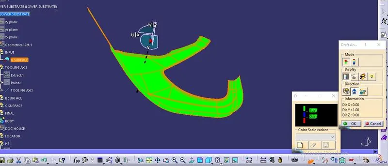
1)Once the tooling axis is created , publish it and the component using Publication from tool option .
2)Insert Feature draft analysis option from insert tool bar
3) Change the view option to customize view parameters and click on material option under shading .
4) Now click on the axis option from Draft analysis tools , allign it with tooling axis and click on lock option to lock it .
5) Change draft angle value to 3 degree . Click on quick analysis mode to display feature according to given color scale . Check from all views to ensure the draft analysis is cleared
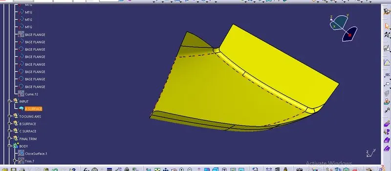
3.MAP POCKET
Tooling axis for map pocket
Follow the same draft analysis method
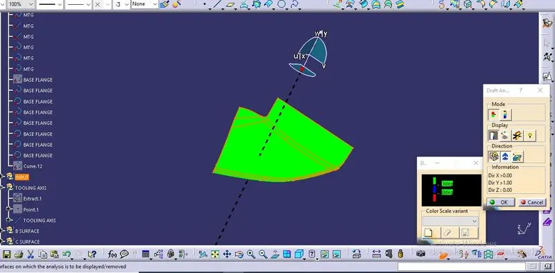
4. LOWER MAP POCKET OR BOTTLE HOLDER
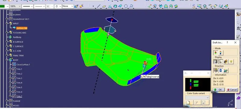
Here we can observe that regions in blue colour has a 0 degree draft angle . This would lead to ejection problems while molding process . Hence the class A surface has to be modified to meet draft requirements Hence we have created tooling axis for all.
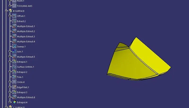
CREATION OF CLASS B SURACE
FOR LOWER SUBSTRATE
Procedure to create class B surface for Lower substrate .
1: Use offset tool with a distance value of 2.5mm to create offset of class A surface .
2: After offset , extrapolate tool was used to extend all the edges of this surface . This is done to ensure that the parting line comes at B surface .
3: In areas where extrapolate was not possible (Fillet or cusped surfaces) multisection surface option was used .
4: Join all the extrapolated surface and multi section surfaces to obtain a single surface .
Hence the class B surface was created for lower substrate .
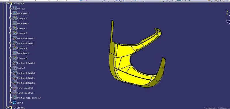
FOR ARM REST
Offset the surface into 2.5mm to consider the arm rest coating to comfort
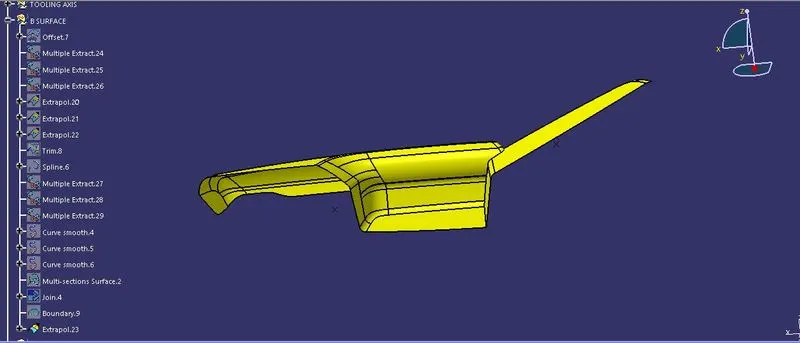
FOR LOWER MAP POCKET OR BOTTLE HOLDER
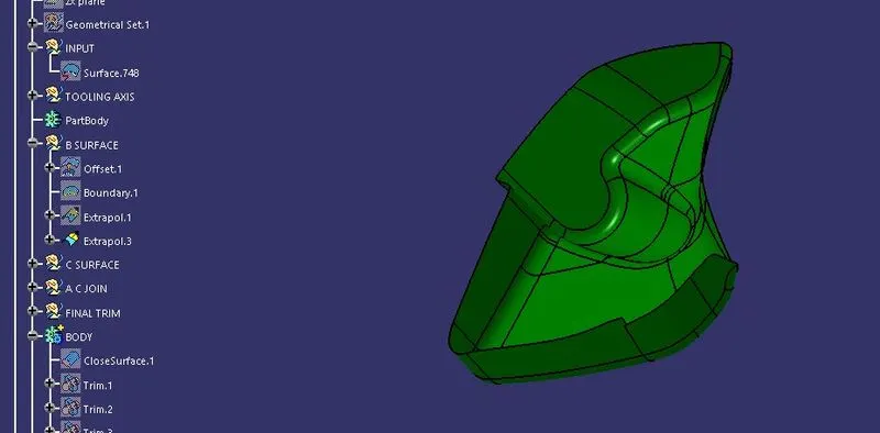
FOR MAP POCKET
CLASS C CREATION
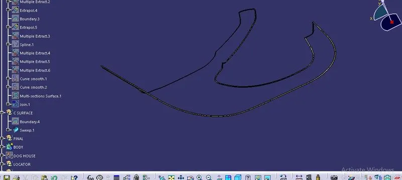
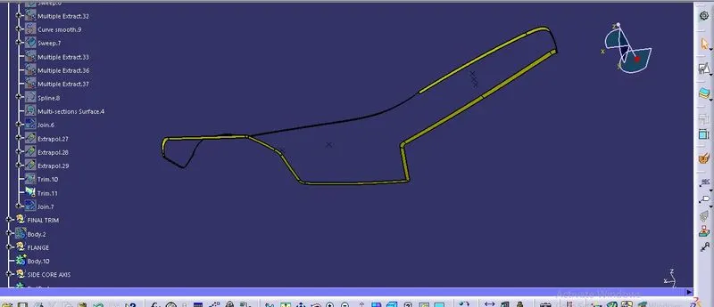
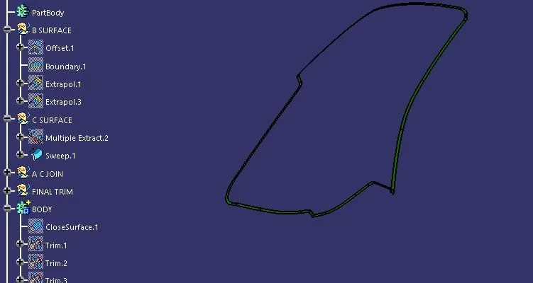
1. Use sweep command to create a new surface an an angle with respect to a surface . This angle is dependant on draft angle for free edges and ususally 90 degree for mating surfaces .
2. Join all surfaces to obtain C surface.
FOR LOWER SUBSTRATE
FOR ARM REST
FOR LOWERMAP POCKET
FOR MAPPOCKET
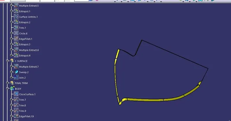
TO CREATE THE CLOSED BODY
Procedure for creation of closed body for lower map pocket .
Step 1: Use trim or join option to join Class A and Class C
Step 2: Use trim option to join above trim with class B
FOR LOWER SUBSTRATE
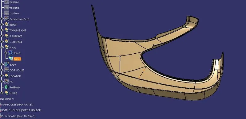
FOR ARM REST
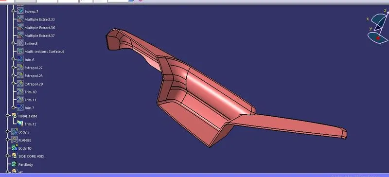
FOR MAPPOCKET
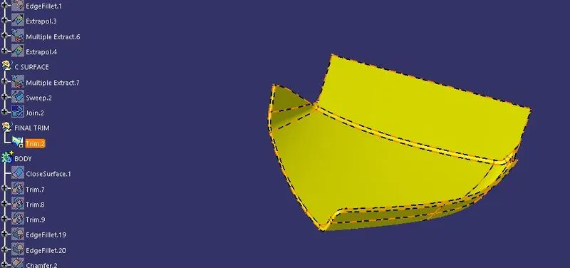
FOR LOWERMAP POCKET
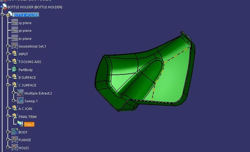
FLANGE CREATION
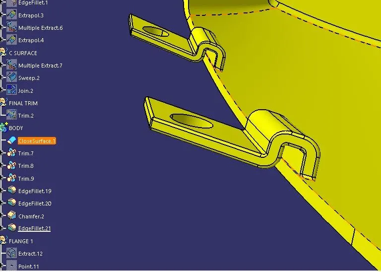
1.Using given master section create flange in the sam eplane using the same exact dimention
2.After pad in the direction of the lower substrate
3.Give proper edge fillet and check the dimention with master section.
4.If the part is finalised copy and transalate to next area
5.Create next type flanges with dimensions.
6.Pad it and give neccesary fillets
7.Copy and transalate the flanges
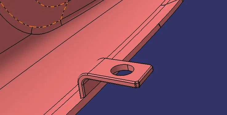
HEAT STAKES
1.Heat stakes diameter is taken from the master section
2.Pad it and give fraft as.5 degree
3.give neccesary edge fillets
4. Ribs are also provided to create support
5. Sketch created and pad it along the axis
6.Provide draft as.5 degree and provide fillets
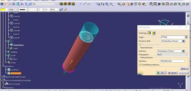
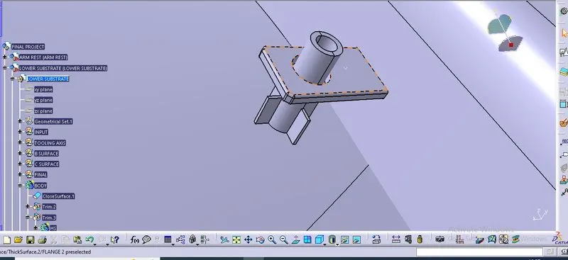
Dog House
!.Create sketch on the surface as 30x 30
2.Pad the sketch into 40 mm
3.Give draft as 1.5 degree
4.Give the edgefillets and neccesary operation
5.Follow the rule create inner surface
6. Also make rib inside and give draft
7.Make cutting for the push pin above
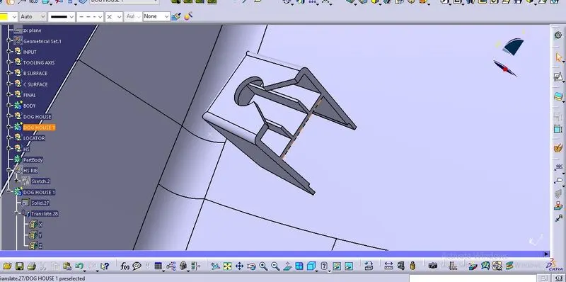
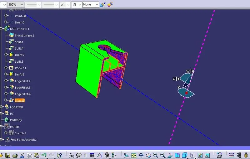
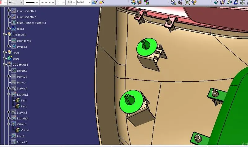
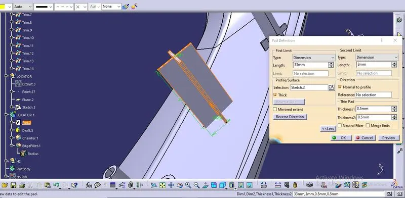
LOCATOR
1.Create a sketch
2. Pad along the tooling axis
3.Give draft in .5 degree and nceesary chamfer with edge fillets
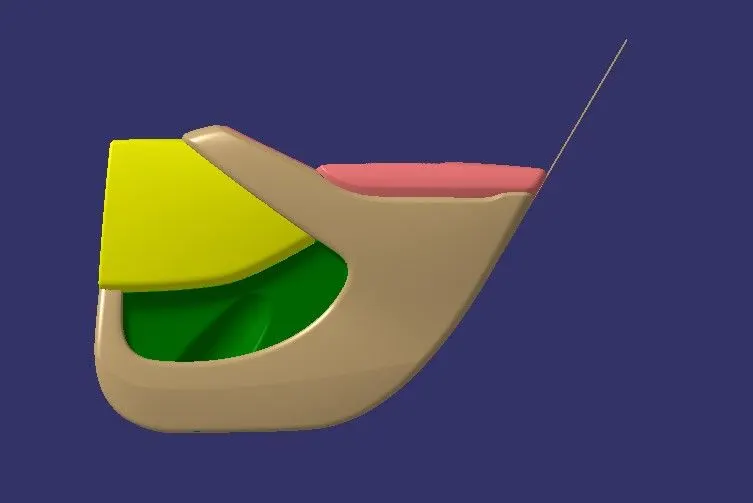
Final product
Front view
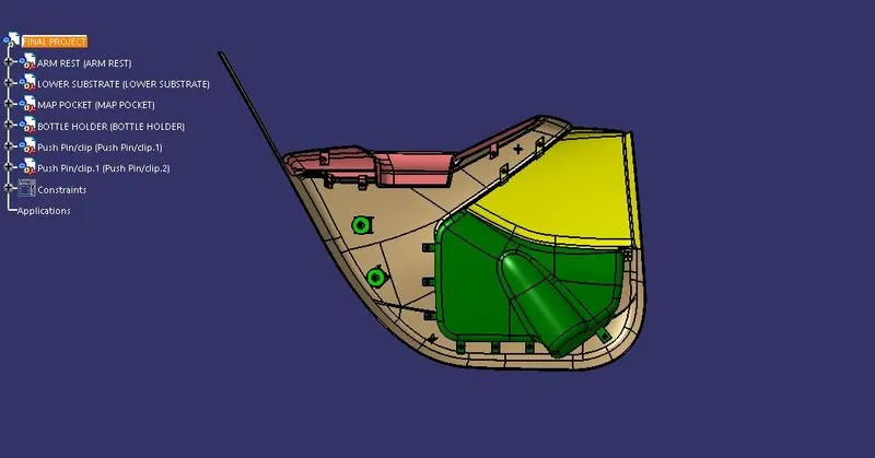
Back view
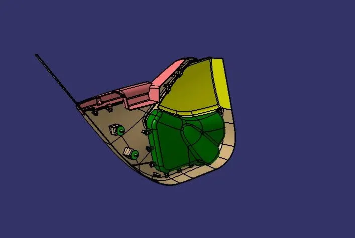
Isometric view
Conclusion
All the part made from the master session by following design rules with B side features