DEVELOPMENT OF DOOR PANEL Industrial standards (CATIA)
DEVELOPMENT OF A DOOR TRIM PANEL
In this project, I will be developing various Class A surfaces of a door panel from a vehicle given by the Class A creation team, and I will work and design the class B surface, class C, and then various plastic parts that can make an Assembled door panel. And also I will be taking some dimensions from the Master Section as an Input. I will work on this project by using the TOP-DOWN approach which will make it easier.
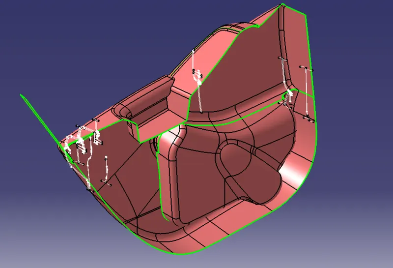
The Class A Surface and Master section is given to me as Input from a Car door panel are
1. Arm Rest of a Door panel
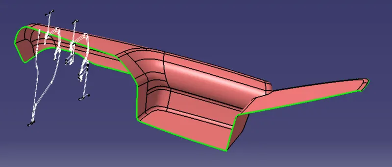
2. Lower Substrate of a Door panel
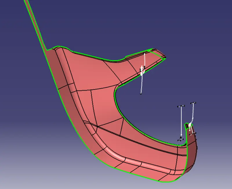
3. Map Pocket (top)
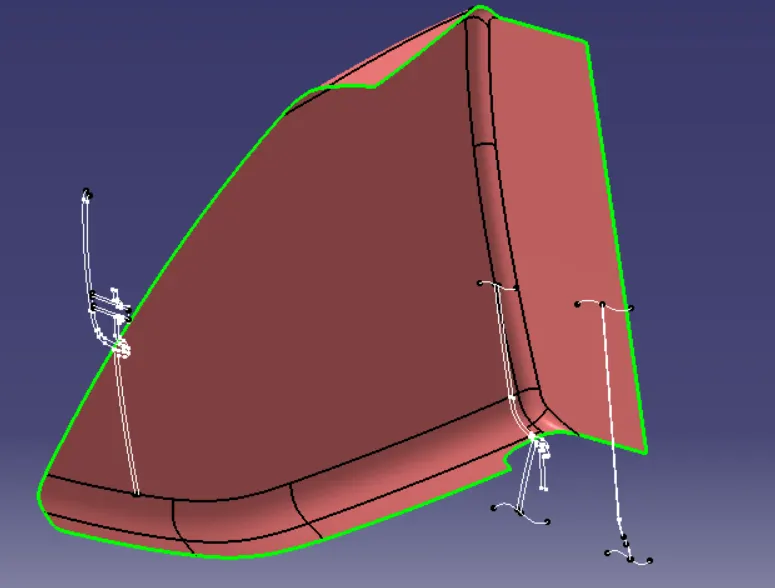
4. Map pocket (Bottle Holder)
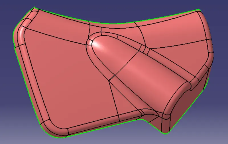
From this Door trim panel as a Class - 'A' surface, first I need to check whether the surface has some boundary irregularities and any open boundaries.
- After checking I need to create a Tooling Axis for the Class - 'A' surface. And also if I need to create the Side core tooling axis for the surface.
- Then I need to create the Class - 'B' and Class- 'C' surface with the help of the Class - 'A' surface And Master sections provided.
Checking for open gaps or boundary irregularities for every given Class-A surface.
1. ARMREST
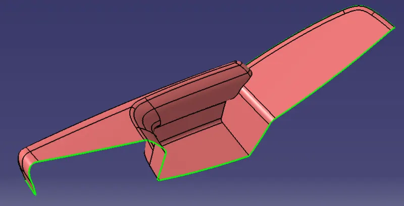
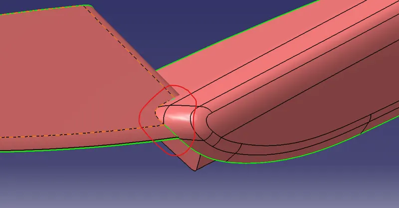
There is one open boundary irregularity found in this surface, So I will repair that open edge and use that as my initial surface to work accordingly.
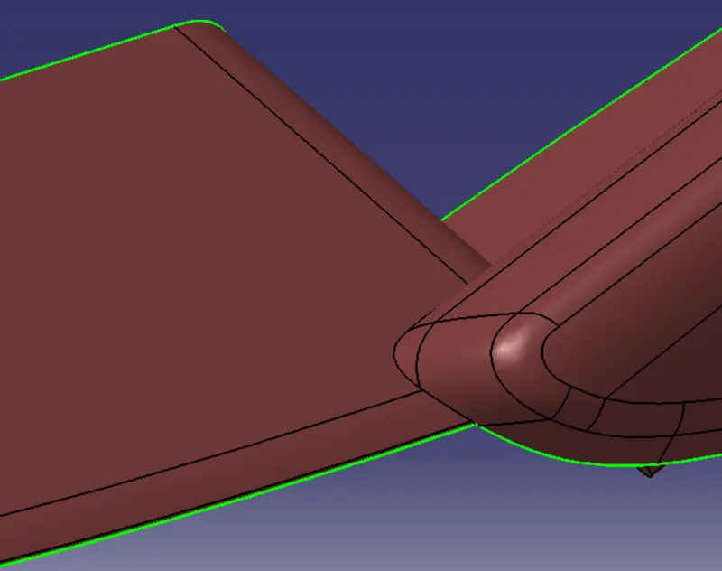
Now this surface is ok to proceed further.
2. LOWER SUBSTRATE
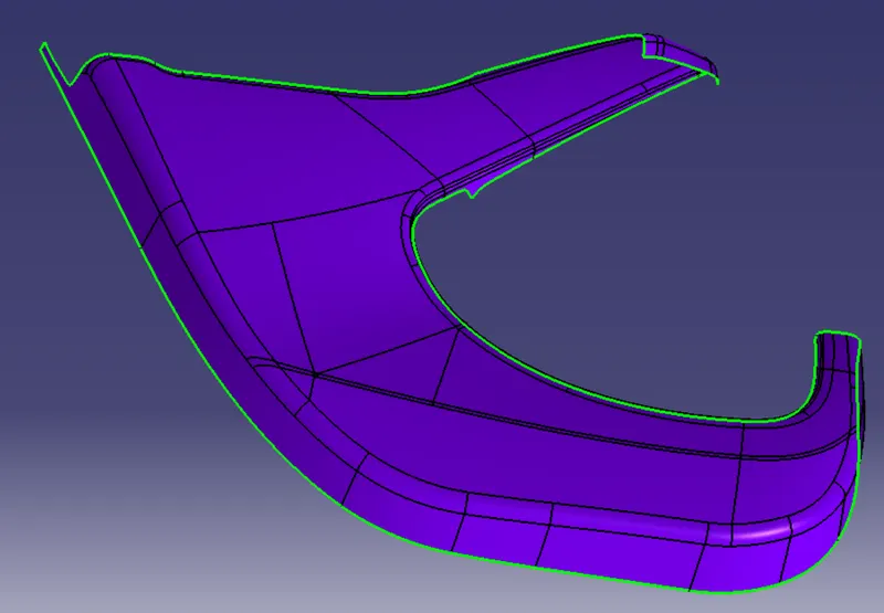
There is no Open Boundary found on this given surface. So, it is OK to use this surface.
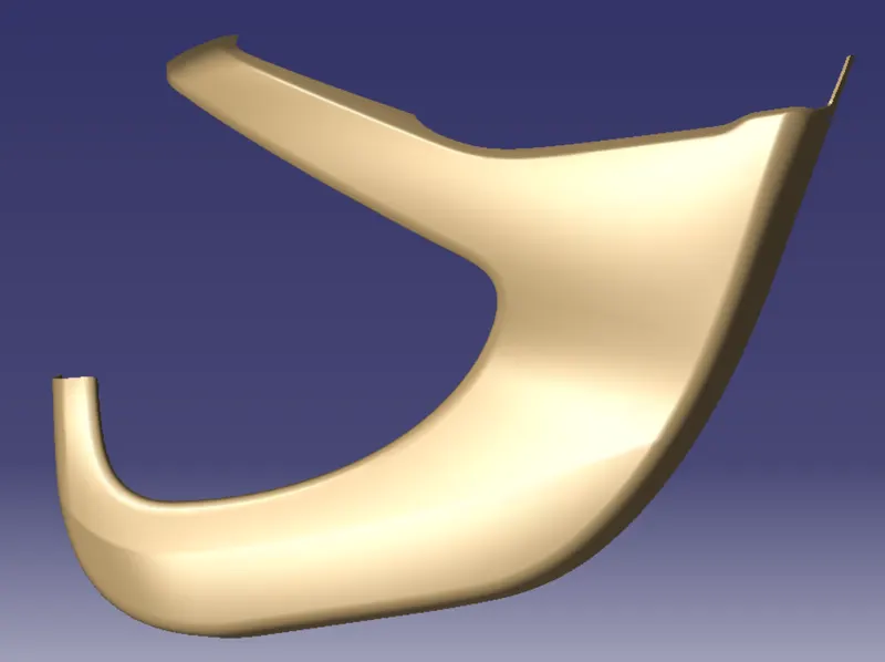
3. MAP POCKET (TOP)
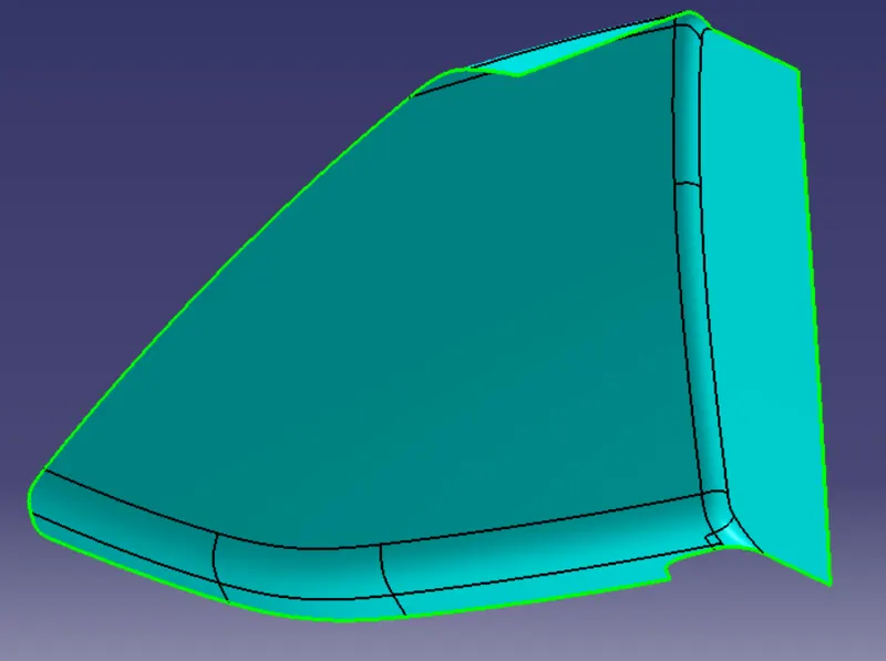
There is no Open Boundary found on this given surface. So, it is OK to use this surface.
4. MAP POCKET (BOTTLE HOLDER)
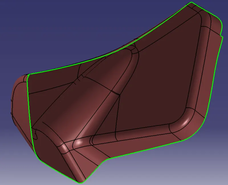
There is no Open Boundary found on this given surface. So, it is OK to use this surface.
- Now the next step is to create the Tooling Axis from the input data for every Part
TOOLING AXIS CREATION
The tooling axis is the direction of drawing a sheet metal where the finished component is easily ejected on a particular direction and axis. The tooling axis is important for removing the material when finished. In this provided surface there are two ways to create a Tooling axis, which are-
- First, I will create an Axis system, from that axis system I will get two cross-sections. by using that cross-section lines I will create the tooling axis for the surface.
- Secondly, there is a Master Section (MS) provided, in that MS I can extract some of the geometry which will be the tooling axis because those MS should have been created by Parent tooling axis and a lot easier than the first option.
I will create a tooling axis by following the first method because the MS which I got is only taken From one side cross-section and it will be difficult to make a tooling axis that will cover from all sides.
1. ARMREST
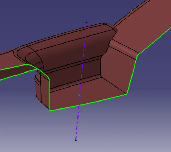
Main tooling axis
I will make 2 sketches from 2 planes and bisecting them to get a tooling axis for that surface
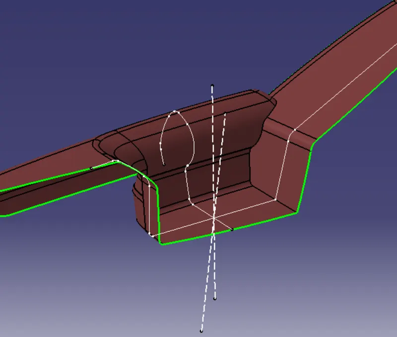
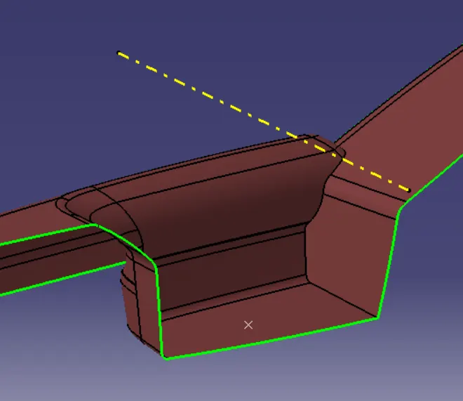
Side tooling axis
I will be making the side tooling axis 90 degrees to the main tooling axis.
2. LOWER SUBSTRATE
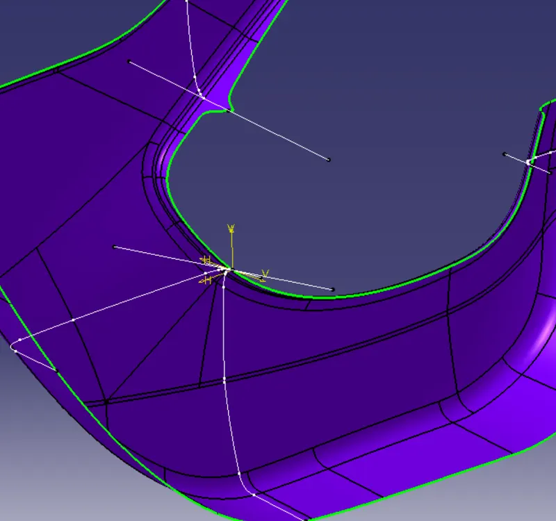
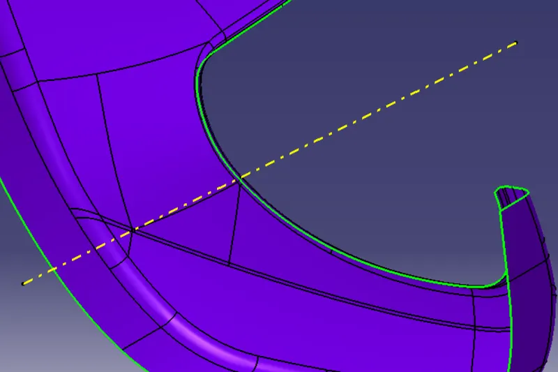
Main tooling Axis
I will make 2 sketches from 2 planes and bisecting them to get a tooling axis for that surface
3. MAP POCKET (TOP)
Main tooling Axis
I will make 2 sketches from 2 planes and bisecting them to get a tooling axis for that surface
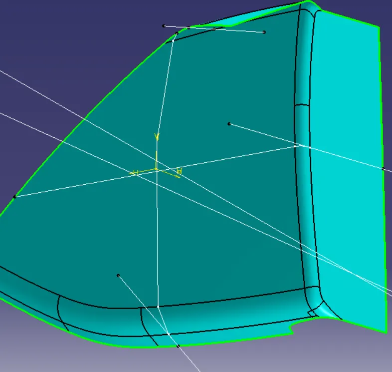
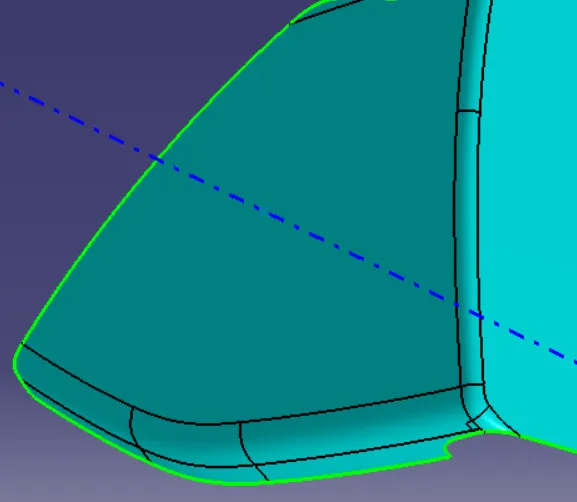
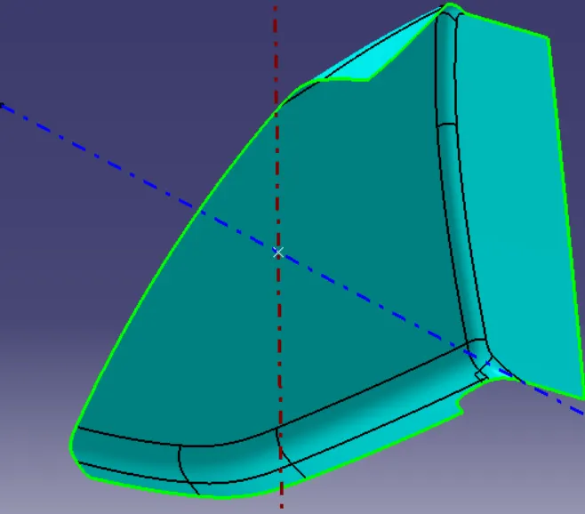
Side tooling axis
I will be making the side tooling axis 90 degrees to the main tooling axis.
4. MAP POCKET (BOTTLE HOLDER)
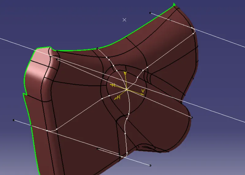
Main tooling Axis
I will make 2 sketches from 2 planes and bisecting them to get a tooling axis for that surface
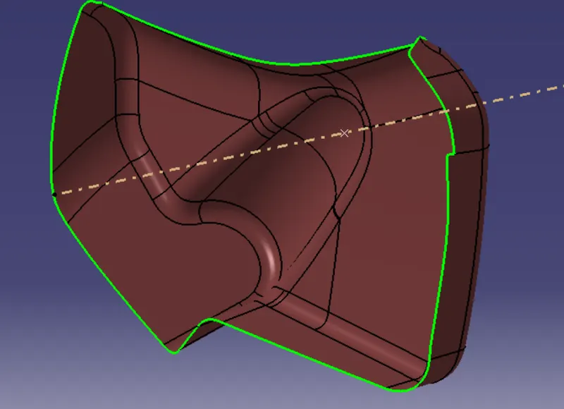
- Now after getting the tooling axis I will now perform a Draft Analysis and check whether the tooling axis is correct or not.
DRAFT ANALYSIS ON CLASS A SURFACE
When a plastic component is made, we can observe that there is a draft angle given on each side from the base which is lesser than 90 degrees. This is because in the criteria of making a plastic material the mold should release the material when finished. if the mold surfaces are 90 degrees the material won't release from the mold because of friction due to contraction of material when cooled.
To resolve this problem we CAD engineers maintain a standard rule to design the plastic mold or die's in such a way that there is no problem while ejecting the plastic component. So a minimum of 3 - 10 degrees of draft angle is given to every plastic component while designing.
1. ARMREST
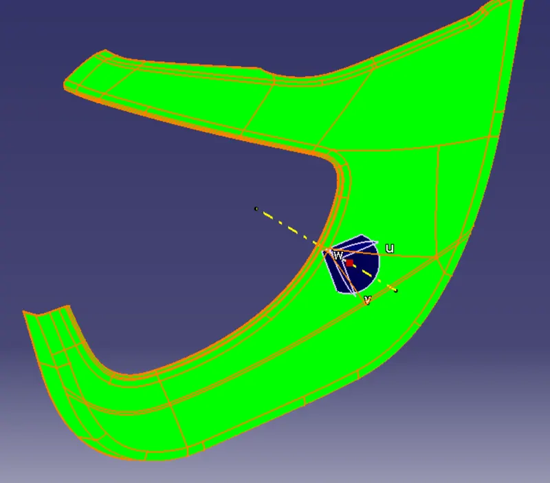
From the created tooling axis, if I see the model from the top, then it has no negative draft.
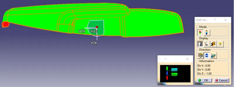
but if I examine the model briefly it has some negative draft.
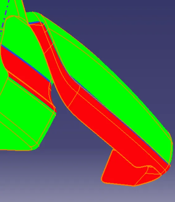
after the errors now I may create a secondary tooling axis ( side core tooling Axis), but for that also there should be a minimum of 3-degree draft angle on all the negative sides of this model.
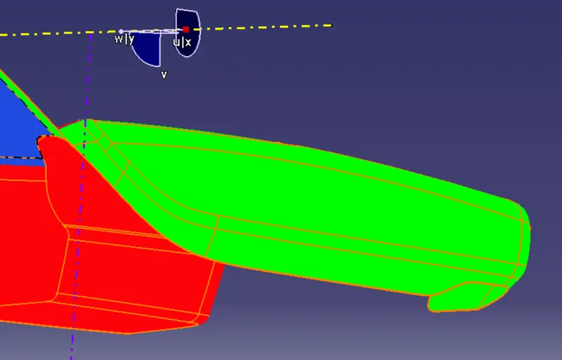
So when I briefly examined the model I observed that the sides have 0 or negative degrees from the tooling axis.
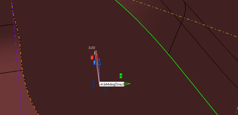
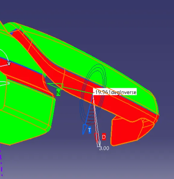
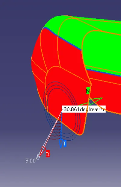
As we can see, these Red surfaces are almost equal to 0 degrees or negative than 0 degrees.
- Now, this is an issue because it will not compete with the recommended classifications of a plastic part manufacturer.
- If the surfaces are at 0 degrees the plastic part won't eject at the end due to contraction after the cooling process.
To tackle this problem there are mainly two reasons which I have come to know.
- one way is to create a secondary and tertiary side core tooling axis to overcome this problem, but the overall point is to manufacture the product with fewer expenses.
- So what I would recommend to the Class - A surface creator to give some draft angles on these sides for 3 to 7 degrees draft to negative sides.
2. LOWER SUBSTRATE
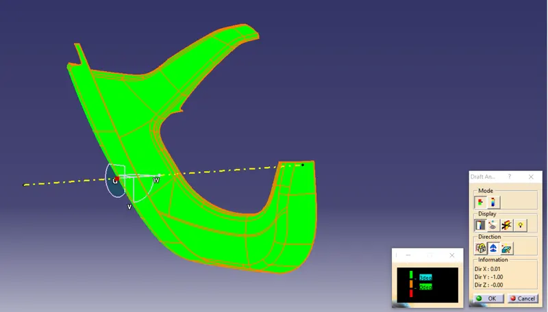
there Is no negative draft on the provided class A surface. So I will continue to make Class B and Class C surfaces respectively.
3. MAP POCKET (TOP)
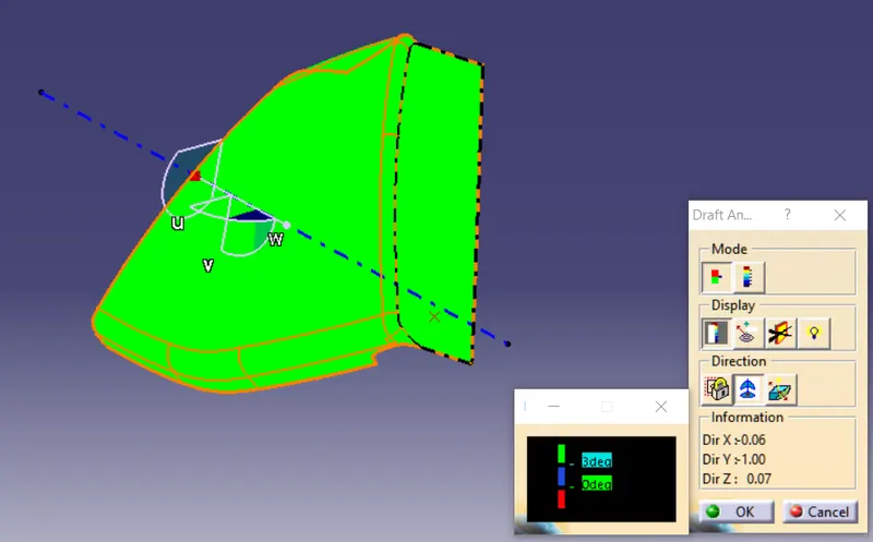
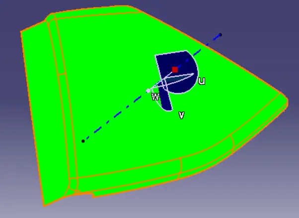
there Is no negative draft on the provided class A surface. So I will continue to make Class B and Class C surfaces respectively.
4. MAP POCKET (BOTTLE HOLDER)
From the created tooling axis, if I see the model from the top, then it has no negative draft.
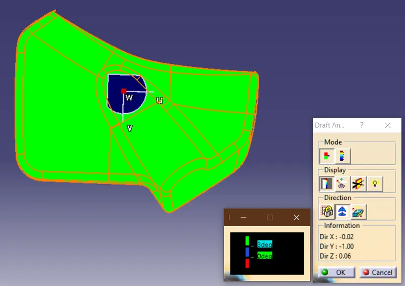
but if I examine the model briefly it has some negative draft.
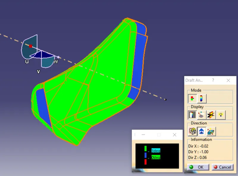
So when I briefly examined the model I observed that the sides have 0 or negative degrees from the tooling axis.
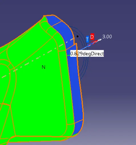
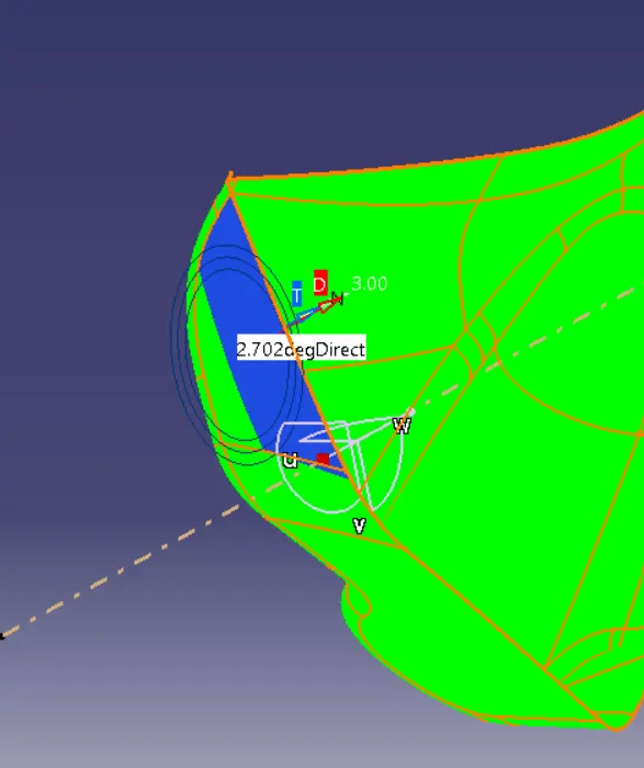
As we can see, these blue Surfaces are almost equal to 0 degrees but not less than 0 degrees, so the manufacturer has to make a more accurate tooling machine.
To tackle this problem there are mainly two reasons which I have come to know.
- one way is to create a secondary and tertiary side core tooling axis to overcome this problem, but the overall point is to manufacture the product with fewer expenses.
- So what I would recommend to the Class - A surface creator to give some draft angles on these sides for 3 to 7 degrees draft to negative sides.
Creation of Class - B, Class - C, and Final surface bodies.
1. ARMREST
Now keeping the draft issues aside, I Will now Create the Class - B and Class - C surface.
- Class- B creation
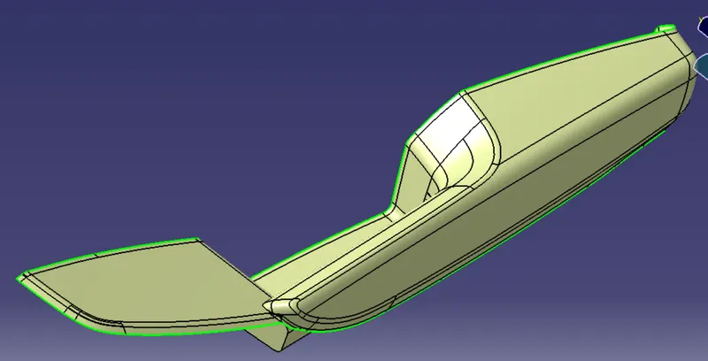
By checking the Master section, the thickness of the Armrest part is about 2.5mm. So offsetting the Class A surface with 2.5 mm and resolving the errors that came by offsetting the class A.
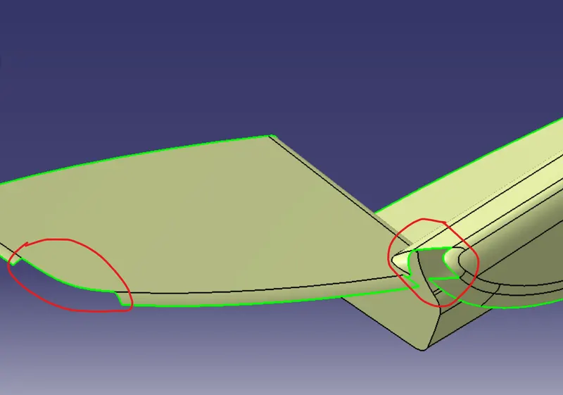
after resolving the Offset errors
- Class - C creation
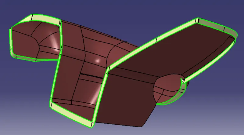
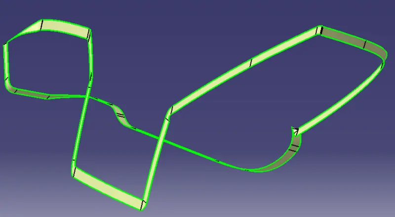
By extracting the boundary of the class - A surface and sweeping them 3 or more degrees angled from the tooling axis, the surface required for class - C is obtained. But in the negative parts of the surface, we can make 90 degrees angle from the surface or the tooling axis.
- Final surface body
By trimming and joining the Class B, Class C, and Class A together the final surface for the Armrest is obtained.
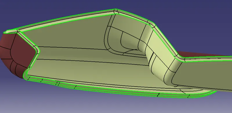
After joining, the only thing to make sure of is to not have any open gap on the final surface.
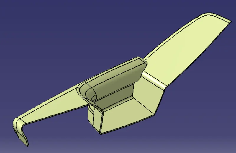
there is no gap found in the final Surface body of the armrest. hence, I can make a solid body out of it.
- Solid-Body
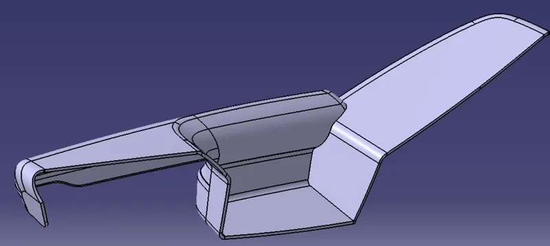
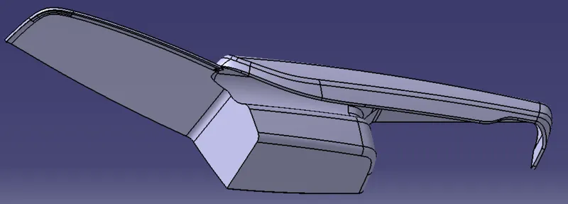
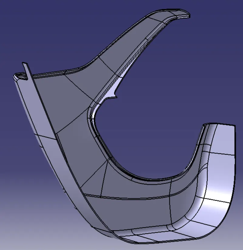
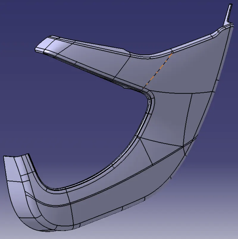
2. LOWER SUBSTRATE
- Class- B creation
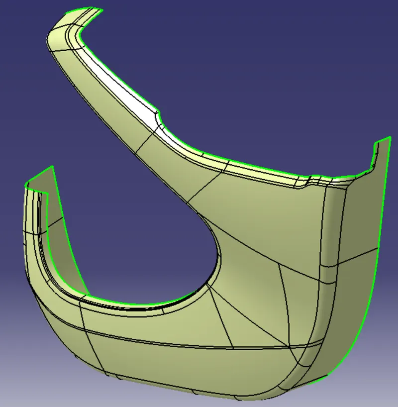
By checking the Master section, the thickness of the lower substrate part is about 2.5mm. So offsetting the Class A surface with 2.5 mm and resolving the errors that came by offsetting the class A.
no errors
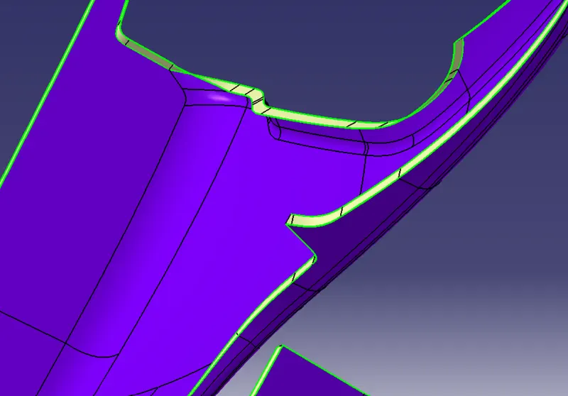
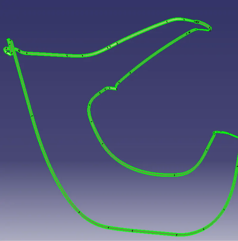
- Class - C creation
By extracting the boundary of the class - A surface and sweeping them 3 or more degrees angled from the tooling axis, the surface required for class - C is obtained. But in the negative parts of the surface, we can make 90 degrees angle from the surface or the tooling axis.
- Final surface body
By trimming and joining the Class B, Class C, and Class A together the final surface for the lower substrate is obtained.
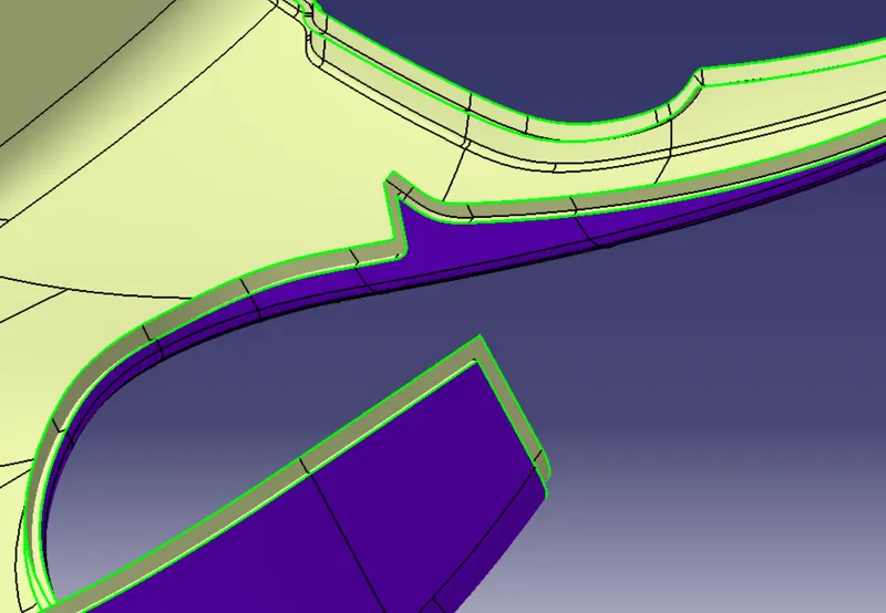
After joining, the only thing to make sure of is to not have any open gap on the final surface.
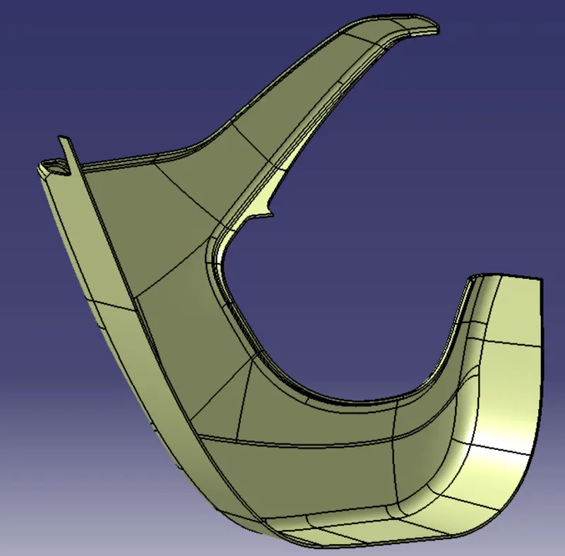
there is no gap found in the final Surface body of the lower substrate. hence, I can make a solid body out of it.
- Solid-Body
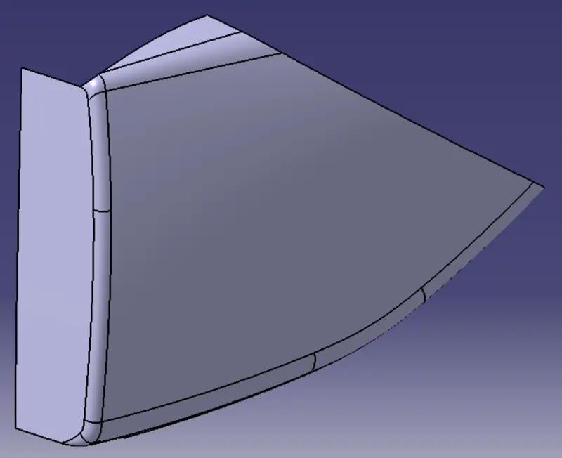
3. MAP POCKET (TOP)
- Class- B creation
By checking the Master section, the thickness of the map pocket (top) part is about 2.5mm. So offsetting the Class A surface with 2.5 mm and resolving the errors that came by offsetting the class A.
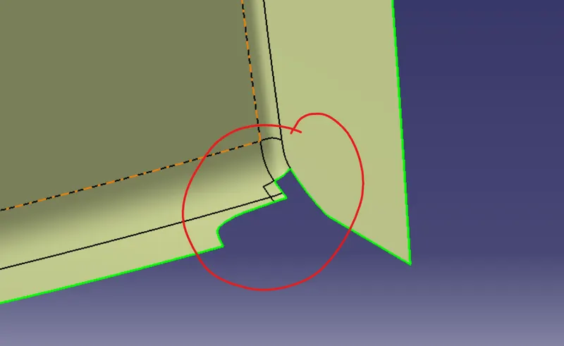
after resolving the Offset errors
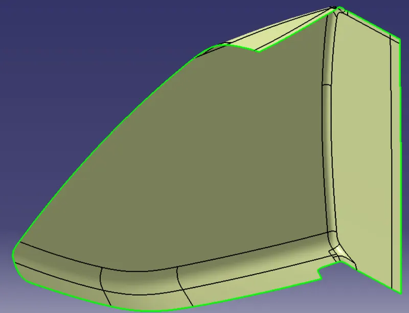
- Class - C creation
By extracting the boundary of the class - A surface and sweeping them 3 or more degrees angled from the tooling axis, the surface required for class - C is obtained. But in the negative parts of the surface, we can make 90 degrees angle from the surface or the tooling axis.

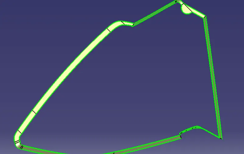
- Final surface body
By trimming and joining the Class B, Class C, and Class A together the final surface for the map pocket(top) is obtained.
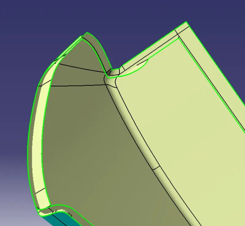
After joining, the only thing to make sure of is to not have any open gap on the final surface.
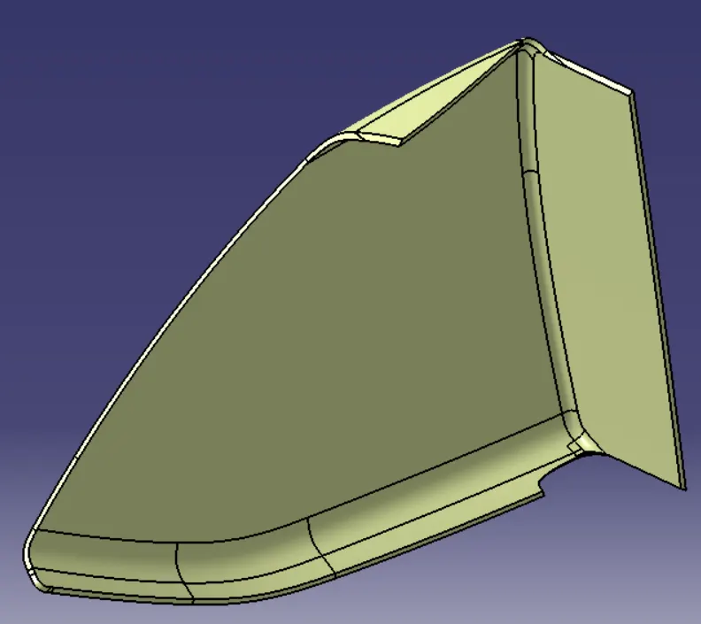
there is no gap found in the final Surface body of the map pocket(top). Hence, I can make a solid body out of it.
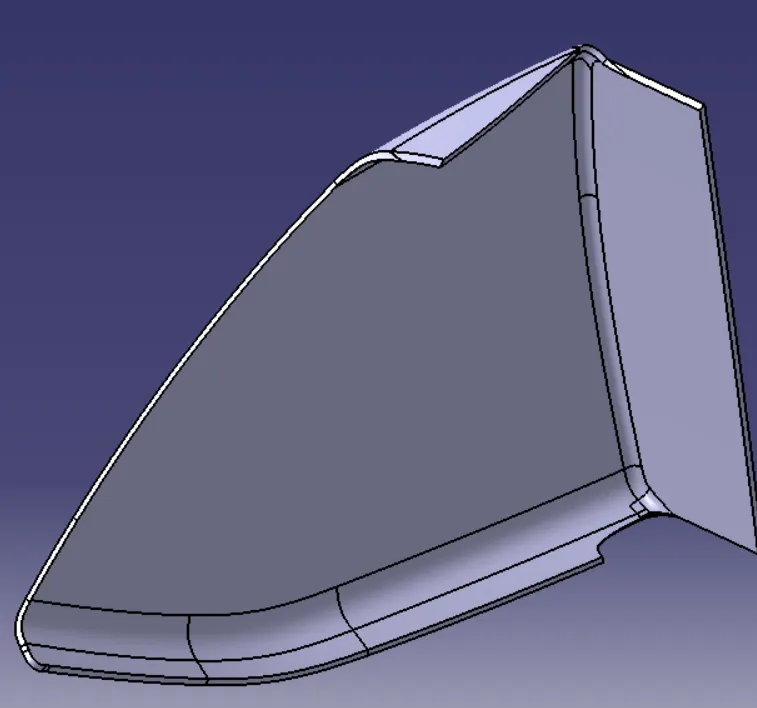
- Solid-Body
3. MAP POCKET (BOTTLE HOLDER)
- Class- B creation
By checking the Master section, the thickness of the map pocket (bottle holder) part is about 2.5mm. So offsetting the Class A surface with 2.5 mm and resolving the errors that came by offsetting the class A.
no errors
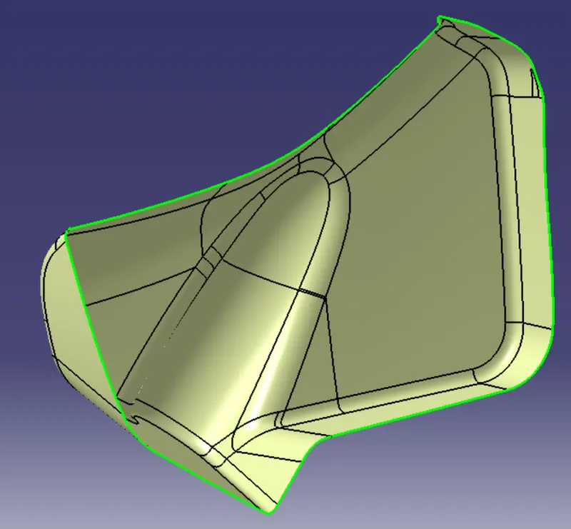
- Class - C creation
By extracting the boundary of the class - A surface and sweeping them 3 or more degrees angled from the tooling axis, the surface required for class - C is obtained. But in the negative parts of the surface, we can make 90 degrees angle from the surface or the tooling axis.
- Final surface body
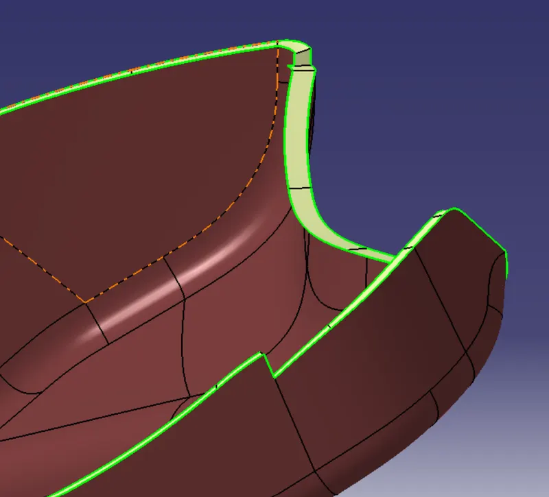
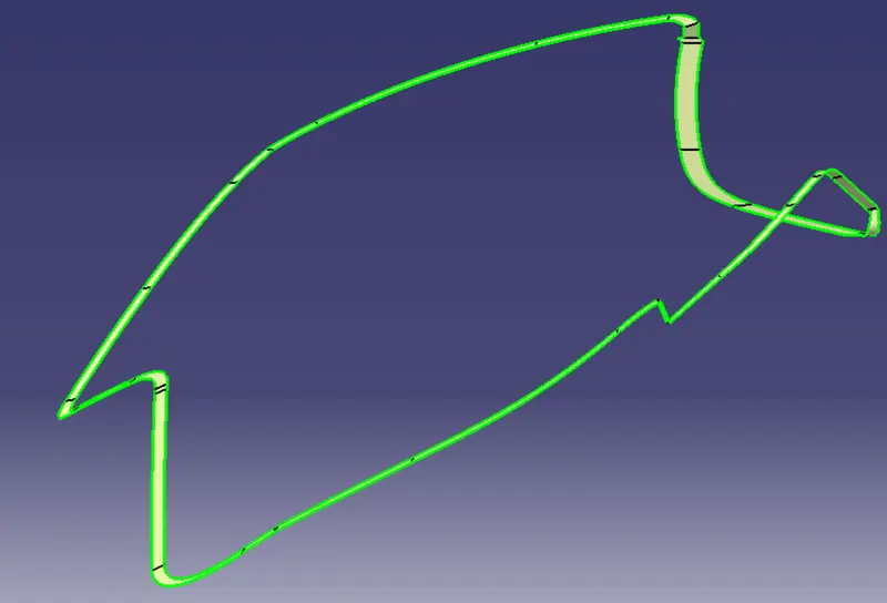
By trimming and joining the Class B, Class C, and Class A together the final surface for the map pocket (bottle holder) is obtained.
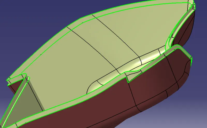
After joining, the only thing to make sure of is to not have any open gap on the final surface.
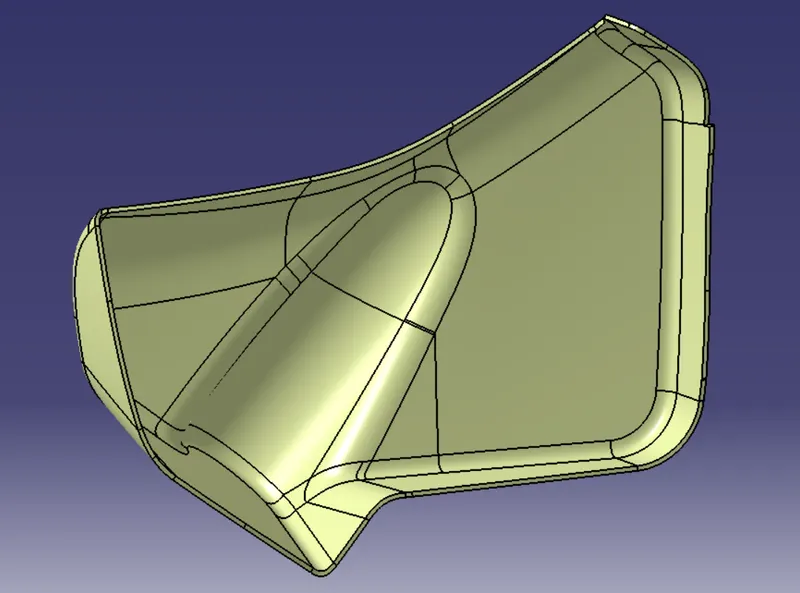
there is no gap found in the final Surface body of the map pocket (bottle holder). Hence, I can make a solid body out of it.
- Solid-Body
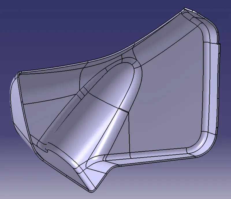
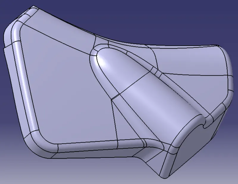
After completing the solid parts of the surface model, I will now continue creating the mounting features with the help of the master sections that are provided.
These are the following mounting features that are to be fixed in the solid part.
- Flanges
- Ribs
- heat steaks
- dog house
- pushpins
- locators
ARMREST
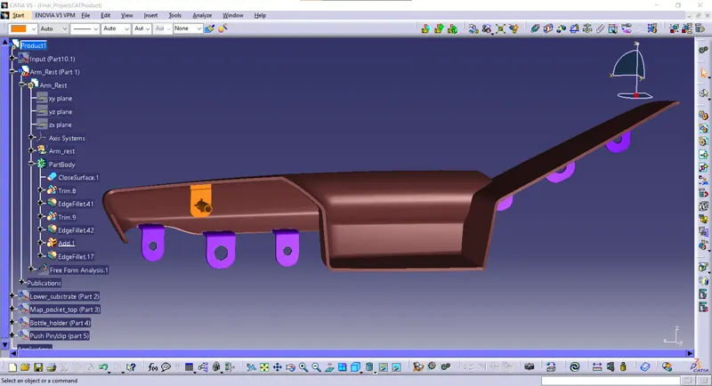
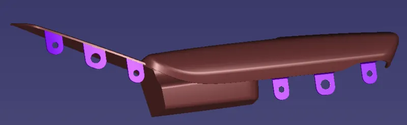
- FLANGES
The function of flanges is to guide and place the opposite components of plastic features like Locators, Heat stakes, etc.
First, let me check the dimensions that can be extracted from the master sections provided.
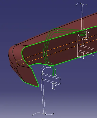
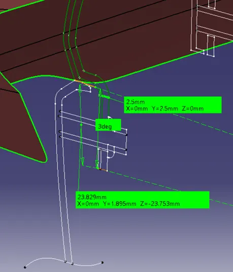
The thickness of the flange should be 2.5 mm and the length of the flange is around 25mm.
I will make the flanges from the surface workbench and then converting them to solid parts.
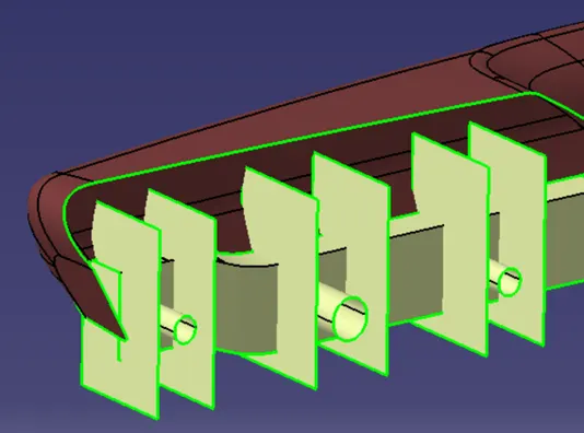
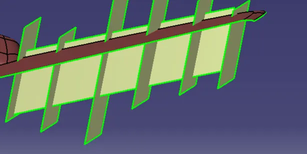
Solid model
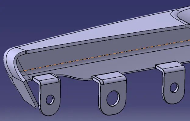
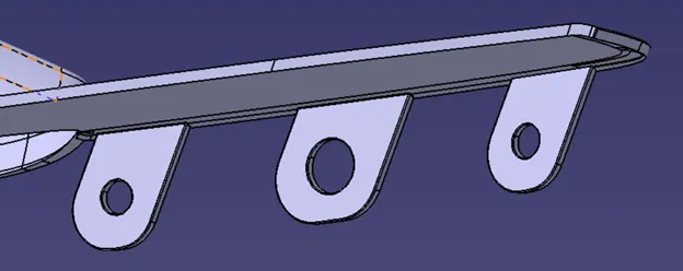
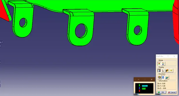
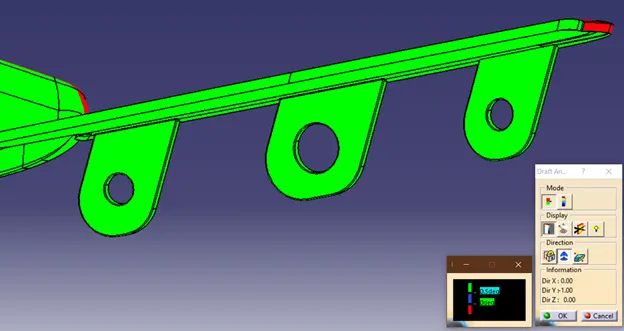
The center flange is for the locator and the other 2 are for the heat stakes. The distance between the center of the flanges is to be around 60 to 100mm.
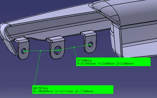
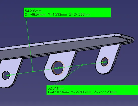
0.5-degree draft given to the flanges.
HEATSTAKES
Heat staking
This is also a fixing method of a plastic component to another dissimilar or similar surface or metal part. But in this process, both of them are joined together by thermal welding and can not be removed after that. A Boss or a stud is made on the plastic part, which is then protruded onto the opposite part and reformed after the locators fix the part temporarily and then thermal welded on the boss.
First, let me check the dimensions that can be extracted from the master sections provided.
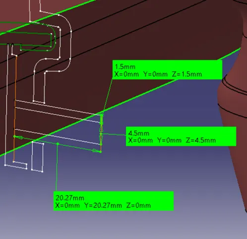
The thickness of the heat steak is 1.5 mm the diameter is around 4.5 mm, the height of the heat steak is around 20 mm and it should have a 0.5-degree draft from the tooling axis
I will make the flanges from the surface workbench and then converting them to solid parts
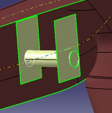
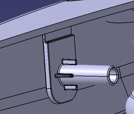
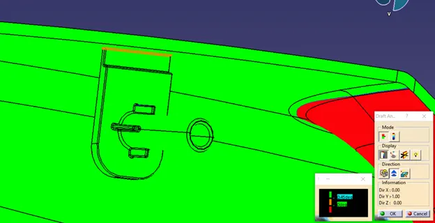
the draft analysis result is positive.
LOWER SUBSTRATE
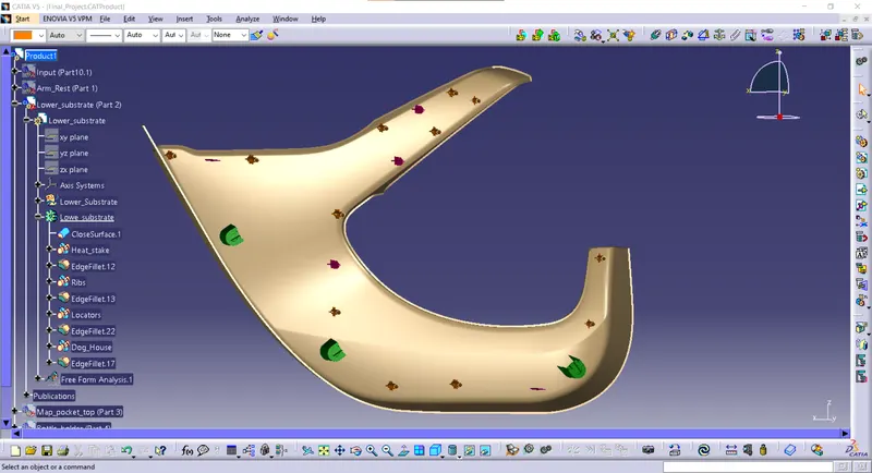
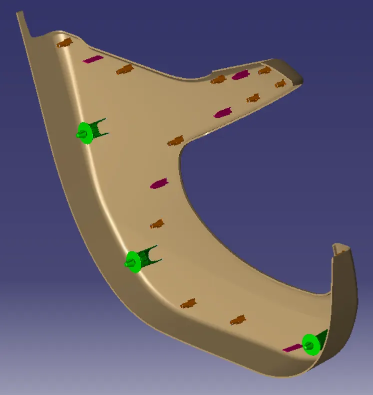
- HEATSTAKES
Heat staking
- This is also a fixing method of a plastic component to another dissimilar or similar surface or metal part. But in this process, both of them are joined together by thermal welding and can not be removed after that. A Boss or a stud is made on the plastic part, which is then protruded onto the opposite part and reformed after the locators fix the part temporarily and then thermal welded on the boss.
First, let me check the dimensions that can be extracted from the master sections provided.
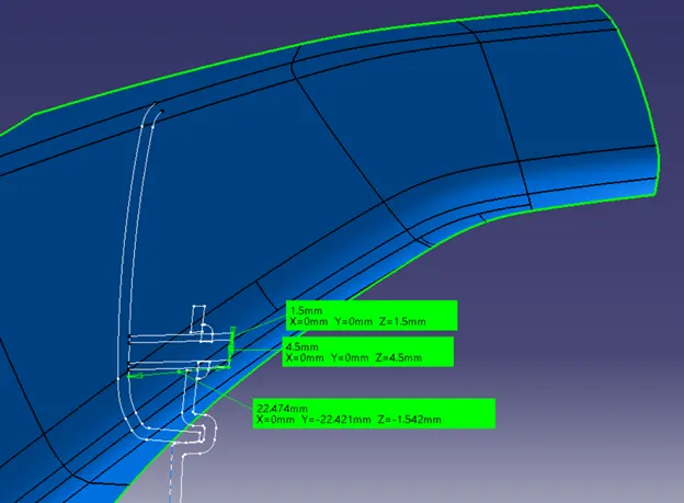
The thickness of the heat steak is 1.5 mm the diameter is around 4.5 mm, the height of the heat steak is around 20 mm and it should have a 0.5-degree draft from the tooling axis.
I will make the Heat stakes from the surface workbench and then converting them to solid parts
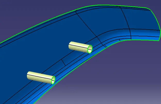
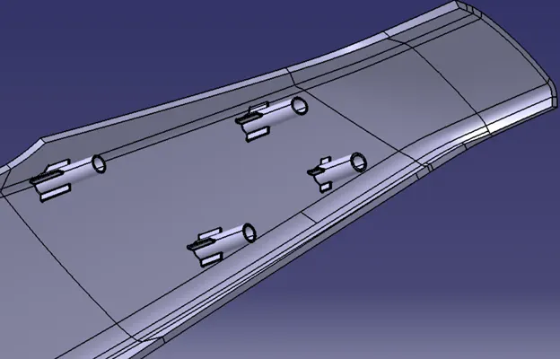
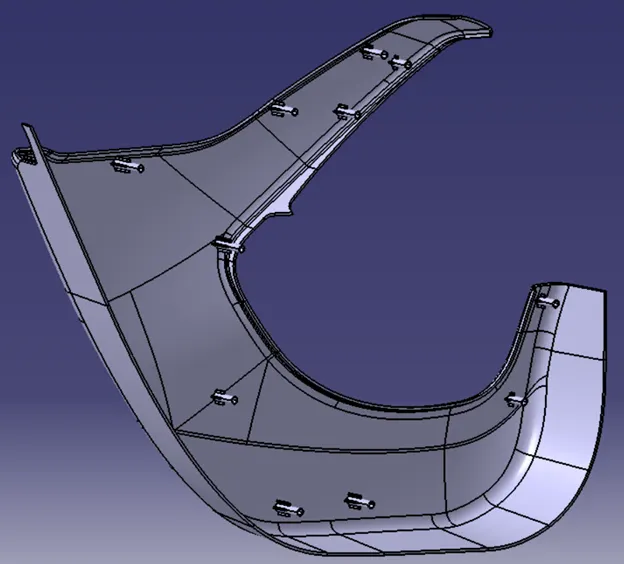
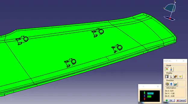
the draft analysis result is positive.
DOG HOUSE
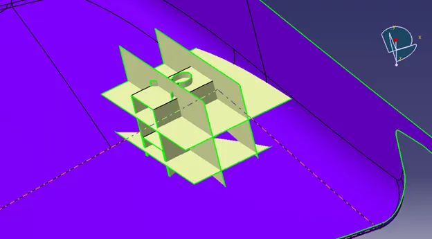
the function of the dog house is to elevate the screw boss or any other part to touch the datum surfaces. in some cases, the fixing part is not touched by the plastic part to tighten, so a dog house is used to resolve this problem.
The intersection part where the main part and dog house meets should have the 40% of thickness to the main part.
and the height of that intersection should be 3 to 6 mm and it should be linear to the tooling axis.
The thickness value at the intersection is 40% of 2.5 mm
which is 1 mm, and after applying the draft value the thickness at one side is 1 mm and at another, it is 1.5 and above.
I Will create the Dog house with the help of inputs provided to me.
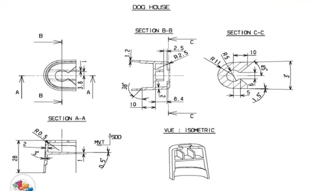
(image given from Skill – Lync course)
I will make the Dog house from the surface workbench and then converting them to solid parts.
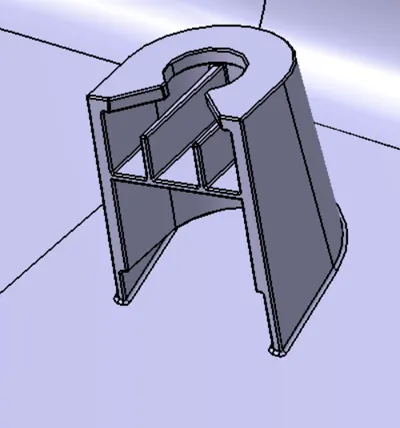
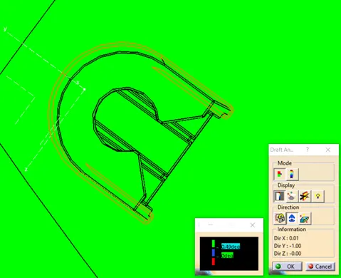
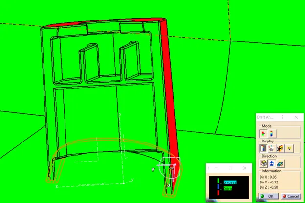
0.5-degree draft is applied to all sides from the tooling axis
From top
From Side
PUSHPINS
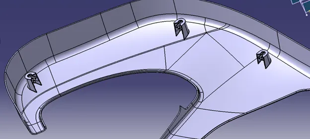
The function of the pushpin is to fit the plastic part to the mating part temporarily and can be replaced if damaged. These clips work as fasteners that will hold the position of the plastic part over time.
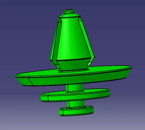
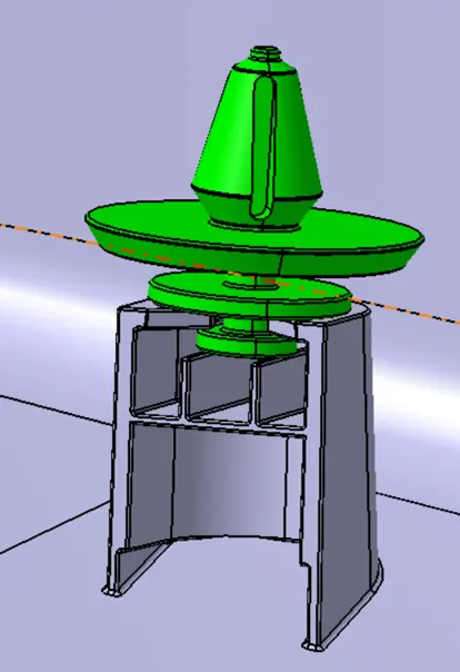
I Will create the Pushpins with the help of inputs, and also part Body of a push pin is provided to me. So, I will use that part and assemble it to the Door panel.
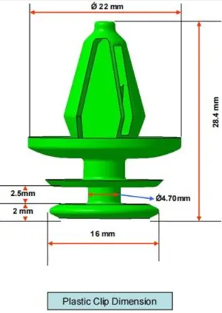
(image taken from Skill – Lync course)
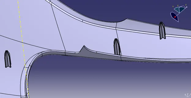
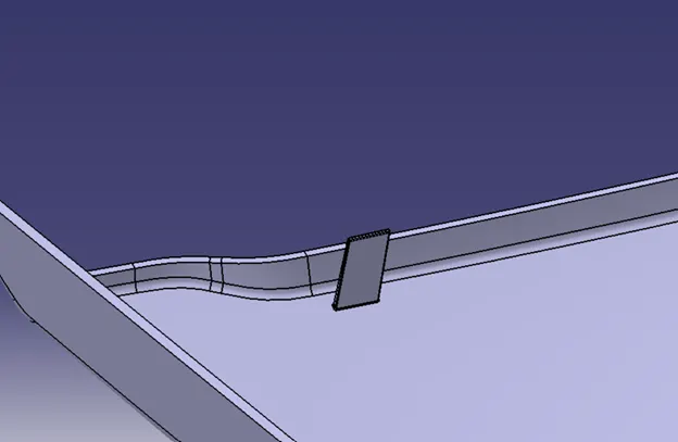
LOCATORS
So what are Locators?
Locators work as a 3 - 2 - 1 principle which is basically to fix a component to be machined or to be placed in an ideal position. There are a total of 12 degrees of freedom, 6 rotational and 6 translational.
In this, I need to fix any 11 degrees of freedom permanently and anyone to be clamped or fixed temporarily. In this scenario, Locators come into place. there are 4-way locators, 3-way locators, and more.
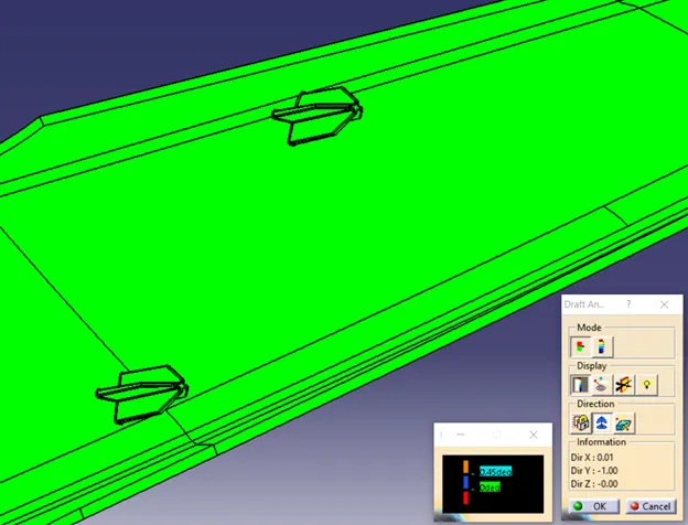
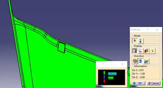
while making a locator the distance of all locators from the surface should be equal for all. The thickness for all should be around 1 mm. A minimum of .25 mm to 0.5 mm drafting is given to validate in draft analysis. And by placing these locators, we can arrest 11 degrees of freedom.
4 - way Locators and 2 - way locators
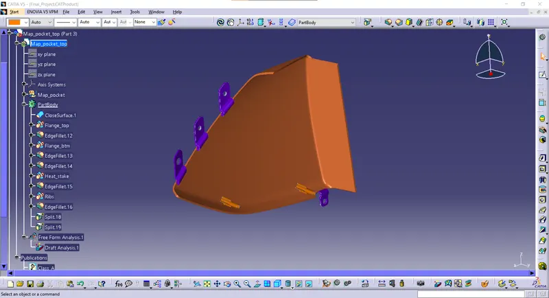
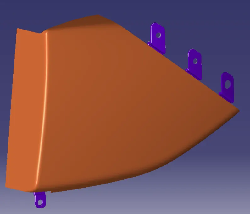
MAP POCKET (TOP)
- FLANGES
The function of flanges is to guide and place the mating components with plastic features like Locators, Heat stakes, etc.
First, let me check the dimensions that can be extracted from the master sections provided.
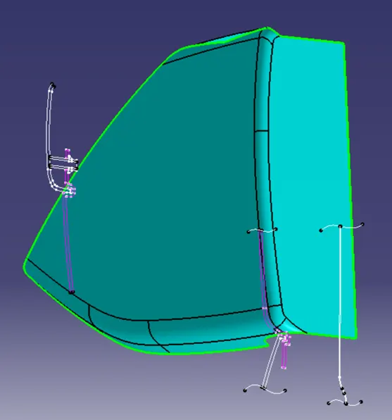
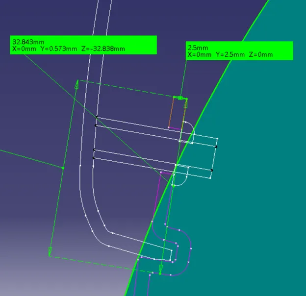
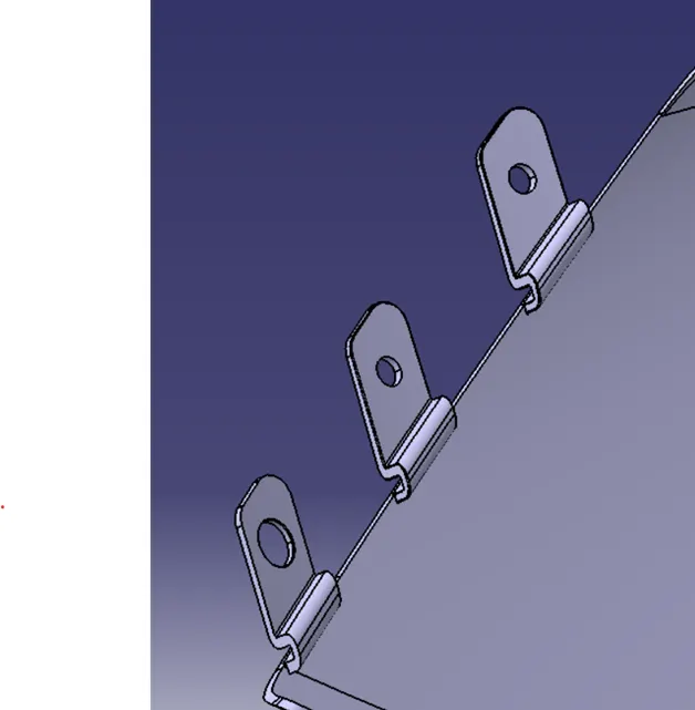
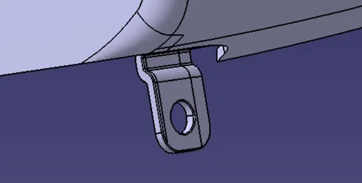
The length of the flange is around 30 mm with a hem-type bend. And the thickness of the flange is 2.5 mm. and a 4.5 mm hole on the center with some allowance for the heat stake to enter and fix.
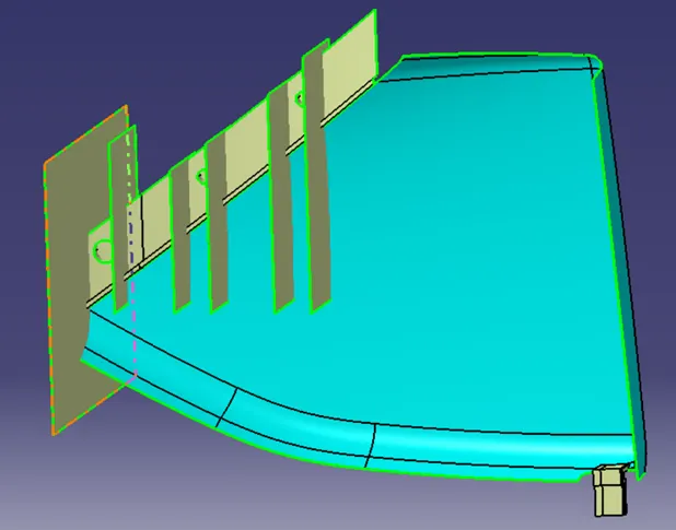
I will make the flanges from the surface workbench and then converting them to solid parts.
HEATSTAKES
Heat staking
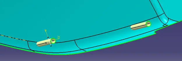
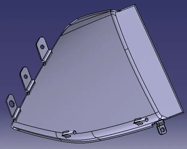
- This is also a fixing method of a plastic component to another dissimilar or similar surface or metal part. But in this process, both of them are joined together by thermal welding and cannot be removed after that. A Boss or a stud is made on the plastic part, which is then protruded onto the opposite part and reformed after the locators fix the part temporarily and then thermal welded on the boss.
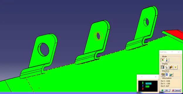
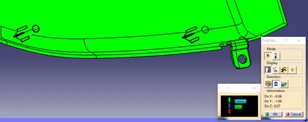
the draft analysis result is positive.
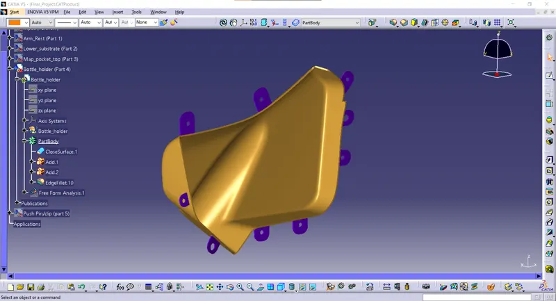
MAP POCKET (BOTTLE HOLDER)
- FLANGES
The function of flanges is to guide and place the mating components with plastic features like Locators, Heat stakes, etc.
I will input the dimensions taken and applied from the other parts
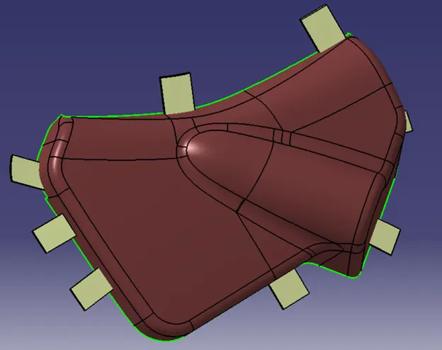
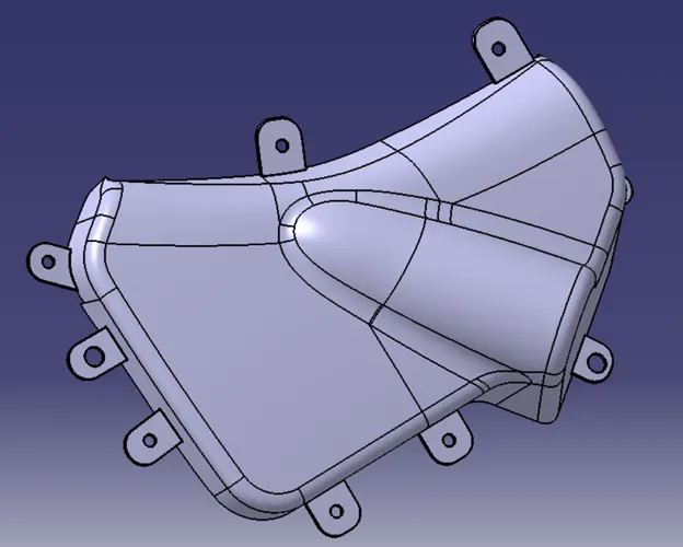
There are two ways we can convert the surface body to solid,
- Creating an open surface and then thickening them in solid workbench
- Another way is to create a closed surface body and the using close surface command in the solid workbench.
in this model, I'm going to create a solid body from the second method.
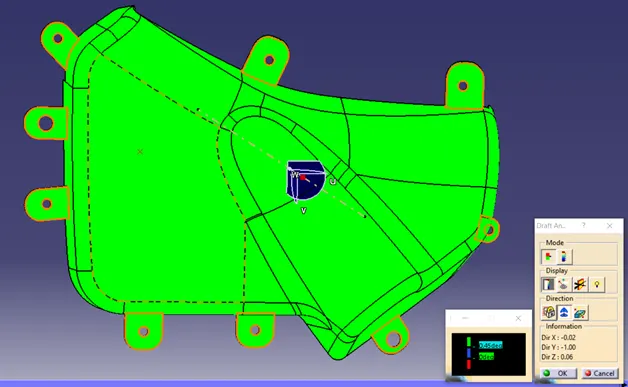
After creating all the mounting features for each model, let's check the model.
FINAL DOOR PANEL
Arm Rest
Lower Substrate
Map pocket - top
Map pocket - bottle holder
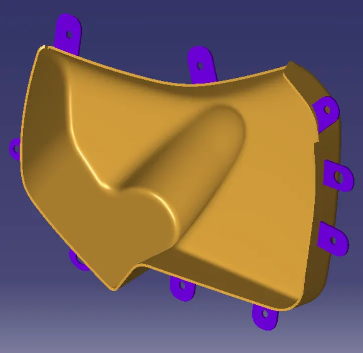
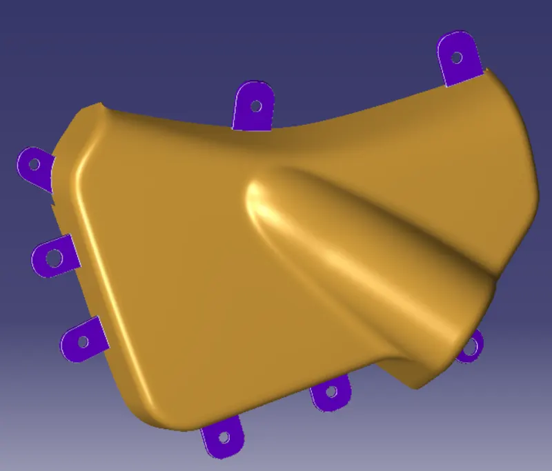
Over All Model
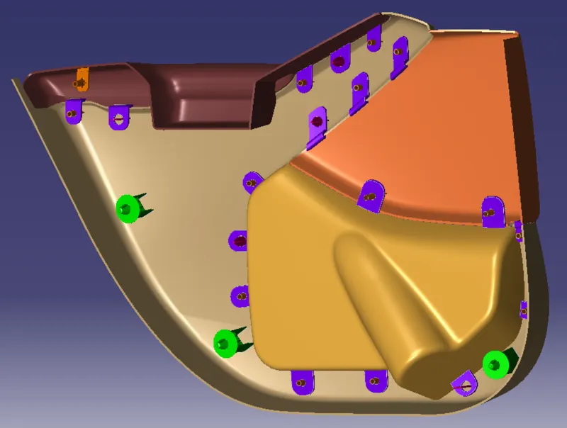
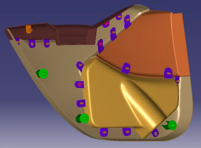
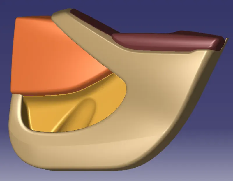
there can be more additional features that can be added to this part and it's endless.
After creating this Final project, I now have the knowledge of surface modeling, Solid modeling, Drafting, Boolean operation in Catia software.