Week-11 Challenge: Braking
1.0
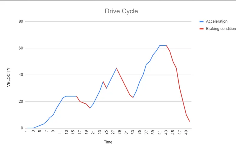
I have considered a drive cycle from the net and considered 4 different cases of braking condition of the cycle and calculate each case brake energy and sum up to get the final brake energy.
To calculate the braking energy for each situation, we can use the formula:
E_braking = 0.5 * Mt * (Vi^2 - Vf^2), where
E_braking is the braking energy,
Mt is the total weight,
Vi is the initial velocity, and
Vf is the final velocity.
First, we need to convert the velocities from km/h to m/s by multiplying by (1000 m/km) / (3600 s/h).
Let's calculate the braking energy for each situation:
- First Braking: 24 - 15 km/h in 4 seconds
Vi1 = 24 * (1000/3600) = 6.67 m/s
Vf1 = 15 * (1000/3600) = 4.17 m/s
E1 = 0.5 * 1500 * (6.67^2 - 4.17^2) ≈ 21097.2 J
- Second Braking: 35 - 30 km/h in 1 second
Vi2 = 35 * (1000/3600) = 9.72 m/s
Vf2 = 30 * (1000/3600) = 8.33 m/s
E2 = 0.5 * 1500 * (9.72^2 - 8.33^2) ≈ 9462.8 J
- Third Braking: 45 - 23 km/h in 5 seconds
Vi3 = 45 * (1000/3600) = 12.5 m/s
Vf3 = 23 * (1000/3600) = 6.39 m/s
E3 = 0.5 * 1500 * (12.5^2 - 6.39^2) ≈ 47125.8 J
- Fourth Braking: 63 - 5 km/h in 7 seconds
Vi4 = 63 * (1000/3600) = 17.5 m/s
Vf4 = 5 * (1000/3600) = 1.39 m/s
E4 = 0.5 * 1500 * (17.5^2 - 1.39^2) ≈ 210133.8 J
Now, let's sum up the braking energies for all situations:
Total_braking_energy = E1 + E2 + E3 + E4 ≈ 21097.2 J + 9462.8 J + 47125.8 J + 210133.8 J ≈ 344819.6 J
2.0
In braking mode, an electric motor serves as a generator, transforming mechanical energy back into electrical energy. However, an electric motor's ability to provide braking torque at high speeds is limited by several factors:
- Back EMF: When the motor is running at high speeds, it generates a back electromotive force (EMF) that opposes the applied voltage. This reduces the effective voltage across the motor and the current flowing through it, decreasing the available braking torque.
- Heating and thermal limits: Energy is dissipated as heat during braking, primarily in the rotor and stator windings. High braking torque would cause higher currents and, as a result, more heat generation. Thermal limitations for electric motors must not be exceeded to avoid overheating and subsequent motor damage.
- Regenerative braking capability is limited: When an electric motor is utilised for regenerative braking, the electrical energy created is either fed back into the power source or used to recharge the batteries. The power supply or battery charging system, on the other hand, usually has a restricted ability to absorb this energy. As a result, the braking torque available through regenerative braking is restricted.
Electric and mechanical brake coordination:
Electric and mechanical braking systems are coupled in some electric drive systems to improve braking performance, safety, and redundancy. These brakes are commonly combined in two ways: series and parallel braking.
- Series Braking: The electronic and mechanical brakes are deployed successively in series braking. The electric brake is often applied first, slowing the motor and allowing regenerative braking to recover some energy. When the motor has reached a given speed, the mechanical brake is applied to bring it to a complete stop. This configuration ensures efficient braking while also reducing wear on the mechanical brakes.
- Parallel Braking: The electronic and mechanical brakes are deployed simultaneously in parallel braking. This design delivers more braking torque and can be used in situations requiring rapid deceleration or increased safety. Parallel braking also aids in the distribution of braking force between electronic and mechanical brakes, lowering the load on each system.
The choice between series and parallel brakes is determined by the application and its needs, which include energy efficiency, braking performance, and safe
3.0
clear all
close all
clc
w = linspace(0,1000);
T = linspace(0,250);
% motor constants
kc = 0.2; % for copper loss
ki = 0.008; % for iron loss
kw = 0.00001; % for windage loss
conL = 20; % for constant motor losses
% making mesh
[X,Y] = meshgrid(w,T);
OutputPower = (X.*Y); % Torque x Speed = Power
B = (Y.^2)*kc; % copper loss
C = (X.^3)*kw; % winding loss
D = X*ki; % Iron loss
InputPower = OutputPower + B + C + D + conL;
Z = OutputPower./InputPower;
% Set the efficiencies for which the contours will be plotted
V = [0.70 , 0.75 , 0.80 , 0.82 , 0.85 , 0.87 , 0.89 , 0.90 , 0.92];
box off
grid off
contour(X,Y,Z,V);
xlabel('Speed(rad/s)')
ylabel('Torque(N.m)')
hold on
V = [8000,10000];
contour(X,Y,OutputPower,V)
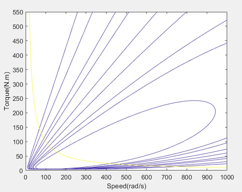
contour lines for the efficiency and output power of the motor.