Week-11 Challenge: Braking
QUESTION:-1 To calculate the energy required for braking in a defined driving cycle, we need to know the mass of the vehicle, the initial velocity, the final velocity, the duration of the braking event, and the braking force.
The formula for calculating the energy required for braking is:
Energy = 0.5 x Mass x (Initial Velocity^2 - Final Velocity^2)
-
Determine the mass of the vehicle.
-
Identify the individual braking events in the driving cycle, and determine the initial velocity, final velocity, duration, and braking force for each event.
FOR EXAMPLE:- IF THE MASS=1600KG
| Time (sec) | velocity (m/s) | FINAL-INTIAL VELOCITY =Q | Q^2 | ||||
| 1 | 0 | 0 | 0 | ||||
| 2 | 0 | 2 | 4 | MASS=1600KG | |||
| 3 | 2 | 1 | 1 | ENERGY=0.5*1600*(F2),NEWTON | |||
| 4 | 3 | 1 | 1 | = | 0 | ||
| 5 | 4 | 0 | 3200 | ||||
| 6 | 2 | 0 | 800 | ||||
| 7 | 1 | 3 | 9 | 800 | |||
| 8 | 4 | 2.5 | 6.25 | 0 | |||
| 9 | 6.5 | 1.3 | 1.69 | 0 | |||
| 10 | 7.8 | 0 | 7200 | ||||
| 11 | 5 | 3 | 9 | 5000 | |||
| 12 | 8 | 2 | 4 | 1352 | |||
| 13 | 10 | 4 | 16 | 0 | |||
| 14 | 14 | 2 | 4 | 7200 | |||
| 15 | 16 | 0 | 3200 | ||||
| 16 | 11 | 0 | 12800 | ||||
| 17 | 9 | 0 | 0 | 3200 | |||
| 18 | 9 | 0 | 0 | 0 | |||
| 19 | 9 | 0 | 0 | 0 | |||
| 20 | 9 | 0 | 0 | 0 | |||
| 21 | 9 | 0 | 0 | ||||
| 22 | 4 | 0 | 0 | ||||
| 23 | 2 | 0 | 0 | ||||
| 24 | 1 | 0 | 0 | ||||
| 25 | 0 | 0 | 0 | 0 | |||
| 26 | 0 | 0 | 0 | 0 | |||
| 27 | 0 | 0 | 0 | 0 | |||
| 28 | 0 | 0 | 0 | 0 | |||
| 29 | 0 | 0 | 0 | 0 | |||
| 30 | 0 | 0 | 0 | 0 | |||
| 31 | 0 | 0 | 0 | 0 | |||
| 32 | 0 | 0 | 0 | 0 | |||
| 33 | 0 | 0 | 0 | 0 | |||
| 34 | 0 | 0 | 0 | 0 | |||
| 35 | 0 | 0 | 0 | 0 | |||
| 36 | 0 | 0 | 0 | 0 | |||
| 37 | 0 | 0 | 0 | 0 | |||
| 38 | 0 | 1 | 1 | 0 | |||
| 39 | 1 | 1.5 | 2.25 | 0 | |||
| 40 | 2.5 | 1.3 | 1.69 | 0 | |||
| 41 | 3.8 | 1.2 | 1.44 | 800 | |||
| 42 | 5 | 2 | 4 | 1800 | |||
| 43 | 7 | 2.9 | 8.41 | 1352 | |||
| 44 | 9.9 | 5.1 | 26.01 | 1152 | |||
| 45 | 15 | 2 | 4 | 3200 | |||
| 46 | 17 | 3 | 9 | 6728 | |||
| 47 | 20 | 2 | 4 | 20808 | |||
| 48 | 22 | 4 | 16 | 3200 | |||
| 49 | 26 | 0 | 7200 | ||||
| 50 | 0 | 0 | 0 | 3200 | |||
| 51 | 0 | 0 | 0 | 12800 | |||
| 52 | 0 | 0 | 0 | 0 | |||
| 53 | 0 | 0 | 0 | 0 | |||
| 54 | 0 | 0 | 0 | 0 | |||
| 55 | 0 | 0 | 0 | 0 | |||
| 56 | 0 | 12 | 144 | 0 | |||
| 57 | 12 | 9 | 81 | 0 | |||
| 58 | 21 | 24 | 576 | 0 | |||
| 59 | 45 | 0 | 115200 | ||||
| 60 | 12.2 | 0 | 64800 | ||||
| 61 | 0.1 | 0.2 | 0.04 | 460800 | |||
| 62 | 0.3 | 14 | 196 | 0 | |||
| 63 | 14.3 | 0 | 0 | ||||
| 64 | 0.25 | 24.05 | 578.403 | 32 | |||
| 65 | 24.3 | 0 | 156800 | ||||
| 66 | 12 | 6.3 | 39.69 | 0 | |||
| 67 | 18.3 | 0 | 462722 | ||||
| 68 | 14 | 5.5 | 30.25 | 0 | |||
| 69 | 19.5 | 0 | 31752 | ||||
| 70 | 14 | 1 | 1 | 0 | |||
| 71 | 15 | 0 | 24200 | ||||
| 72 | 14.5 | 0 | 0 | ||||
| 73 | 12.9 | 5.1 | 26.01 | 800 | |||
| 74 | 18 | 0 | 0 | ||||
| 75 | 14 | 4 | 16 | 0 | |||
| 76 | 18 | 0 | 20808 | ||||
| 77 | 14 | 0 | 0 | ||||
| 78 | 12 | 6 | 36 | 12800 | |||
| 79 | 18 | 0 | 0 | ||||
| 80 | 14 | 0 | 0 | ||||
| 81 | 13 | 1.18 | 1.3924 | 28800 | |||
| 82 | 14.18 | 4.82 | 23.2324 | 0 | |||
| 83 | 19 | 0 | 0 | ||||
| 84 | 14 | 5 | 25 | 1113.92 | |||
| 85 | 19 | 0 | 18585.9 | ||||
| 86 | 17.25 | 0 | 0 | ||||
| 87 | 14.88 | 0.11 | 0.0121 | 20000 | |||
| 88 | 14.99 | 0 | 0 | ||||
| 89 | 14.8856 | 0 | 0 | ||||
| 90 | 14.77 | 0.67 | 0.4489 | 9.68 | |||
| 91 | 15.44 | 3.55 | 12.6025 | 0 | |||
| 92 | 18.99 | 0 | 0 | ||||
| 93 | 14.8 | 0 | 359.12 | ||||
| 94 | 14 | 1.3 | 1.69 | 10082 | |||
| 95 | 15.3 | 10.7 | 114.49 | 0 | |||
| 96 | 26 | 32.8 | 1075.84 | 0 | |||
| 97 | 58.8 | 1.75 | 3.0625 | 1352 | |||
| 98 | 60.55 | 0 | 91592 | ||||
| 99 | 0.88 | 44.12 | 1946.57 | 860672 | |||
| 100 | 45 | 24 | 576 | 2450 | |||
| 101 | 69 | 0 | 0 | ||||
| 102 | 17.89 | 41.1 | 1689.21 | 1557260 | |||
| 103 | 58.99 | 0 | 460800 | ||||
| 104 | 48 | 24.55 | 602.703 | 0 | |||
| 105 | 72.55 | 0 | 1351368 | ||||
| 106 | 0 | 0 | 0 | 0 | |||
| 107 | 0 | 0 | 0 | 482162 | |||
| 108 | 0 | 0 | 0 | 0 | |||
| 109 | 0 | 45.8 | 2097.64 | 0 | |||
| 110 | 45.8 | 0 | 0 | ||||
| 111 | 15.88 | -1 | 1 | 0 | |||
| 112 | 14.88 | 34.92 | 1219.41 | 1678112 | |||
| 113 | 49.8 | 0 | 0 | ||||
| 114 | 19.55 | 46.33 | 2146.47 | 800 | |||
| 115 | 65.88 | 0 | 975525 | ||||
| 116 | 47.99 | 0 | 0 | ||||
| 117 | 47.44 | 0 | 1717175 | ||||
| 118 | 45.88 | 0 | 0 | ||||
| 119 | 17.25 | 0 | 0 | ||||
| 120 | 14.88 | 0.11 | 0.0121 | 0 | |||
| 121 | 14.99 | 0 | 0 | ||||
| 122 | 14.8856 | 0 | 0 | ||||
| 123 | 14.77 | 0.67 | 0.4489 | 9.68 | |||
| 124 | 15.44 | 3.55 | 12.6025 | 0 | |||
| 125 | 18.99 | 0 | 0 | ||||
| 126 | 14.8 | 0 | 359.12 | ||||
| 127 | 14 | 1.3 | 1.69 | 10082 | |||
| 128 | 15.3 | 10.7 | 114.49 | 0 | |||
| 129 | 26 | 32.8 | 1075.84 | 0 | |||
| 130 | 58.8 | 0 | 1352 | ||||
| 131 | 0 | 0 | 0 | 91592 | |||
| 132 | 0 | 0 | 0 | 860672 | |||
| 133 | 0 | 0 | 0 | 0 | |||
| 134 | 0 | 0 | 0 | 0 | |||
| 135 | 0 | 0 | 0 | 0 | |||
| 136 | 0 | 0 | 0 | 0 | |||
| 137 | 0 | 0 | 0 | 0 | |||
| 138 | 0 | 0 | 0 | 0 | |||
| 139 | 0 | 0 | 0 | 0 | |||
| 140 | 0 | 10 | 100 | 0 | |||
| 141 | 10 | 2.5 | 6.25 | 0 | |||
| 142 | 12.5 | 2.5 | 6.25 | 0 | |||
| 143 | 15 | 0 | 80000 | ||||
| 144 | 14 | 4.6 | 21.16 | 5000 | |||
| 145 | 18.6 | 0.4 | 0.16 | 5000 | |||
| 146 | 19 | 6 | 36 | 0 | |||
| 147 | 25 | 2 | 4 | 16928 | |||
| 148 | 27 | 2 | 4 | 128 | |||
| 149 | 29 | 0 | 28800 | ||||
| 150 | 28 | 0 | 3200 | ||||
| 151 | 20 | 0 | 3200 | ||||
| 152 | 15 | 0 | 0 | ||||
| 153 | 10 | 0 | 0 | ||||
| 154 | 5 | 0 | 0 | ||||
| 155 | 0 | 0 | 0 | 0 | |||
| 156 | 0 | 0 | 0 | 0 | |||
| 157 | 0 | 0 | 0 | 0 | |||
| 158 | 0 | 0 | 0 | 0 | |||
| 159 | 0 | 0 | 0 | 0 | |||
| 160 | 0 | 0 | 0 | ||||
| 161 | 0 | 0 | 0 | ||||
Question:-2
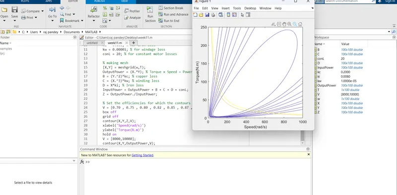
An electric motor cannot develop the same amount of braking torque at high speeds as it can during starting because the motor's back EMF (electromotive force) increases with speed. This back EMF reduces the effective voltage across the motor, which in turn reduces the motor's torque output. At high speeds, the back EMF can become almost equal to the applied voltage, reducing the torque output to nearly zero.
To provide effective braking at high speeds, electric motors are often used in conjunction with mechanical brakes. In this arrangement, the motor is used to slow down the mechanical load, while the mechanical brake provides the necessary stopping torque.The coordination between electric and mechanical brakes can be achieved using a controller that applies the electric brake first to reduce the speed of the load to a safe level and then engages the mechanical brake to bring the load to a complete stop. This approach ensures that the electric brake does not need to provide the full stopping torque, and instead, it is used to slow down the load, reducing the load on the mechanical brake and extending its lifespan.
In some cases, the electric motor can be used to provide regenerative braking, which converts the kinetic energy of the load into electrical energy that can be stored in a battery or used to power other loads. In this case, the electric motor acts as a generator, and the torque output is proportional to the speed of the load. The regenerative braking system can be used in conjunction with a mechanical brake to provide additional stopping power, depending on the requirements of the application.
- Mass of the vehicle
- Initial velocity of the vehicle
- Final velocity of the vehicle
- Time taken to decelerate the vehicle
- Coefficient of rolling resistance
- Coefficient of aerodynamic drag
- Gradient of the road
- Efficiency of the braking system
Once we have this information, we can use the following formula to calculate the energy required for braking:
E = (0.5 x m x (v_i^2 - v_f^2)) + (m x g x d x c_r) + (0.5 x rho x A x C_d x v_i^2 x d x c_a) / eta_b
Where:
- E = Energy required for braking (in Joules)
- m = Mass of the vehicle (in kg)
- v_i = Initial velocity of the vehicle (in m/s)
- v_f = Final velocity of the vehicle (in m/s)
- g = Acceleration due to gravity (9.81 m/s^2)
- d = Distance travelled during braking (in m)
- c_r = Coefficient of rolling resistance
- rho = Density of air (1.225 kg/m^3 at sea level)
- A = Frontal area of the vehicle (in m^2)
- C_d = Coefficient of aerodynamic drag
- c_a = Gradient of the road (in m/m)
- eta_b = Efficiency of the braking system
The first term in the formula represents the kinetic energy of the vehicle, the second term represents the energy lost due to rolling resistance, and the third term represents the energy lost due to aerodynamic drag. The efficiency of the braking system is taken into account in the denominator.
Question:-3