Week-11 Challenge: Braking
Pratik Mankar
AIM
1] For a defined driving cycle, calculate the energy required for braking.
2] Why electric motor can’t develop braking torque at high speed similar to starting? How electric and mechanical brakes are coordinated?
3] Make a MATLAB program which plots contour of given motor speed, torque and efficiency values. Attach the code as a .m file attach a screenshot of all the plots.
1] For a defined driving cycle, calculate the energy required for braking.
A driving cycle is a set of values, generally, velocity vs time, which represents how a vehicle travels through a path. In simple words, it would be a velocity vs time graph of a vehicle.
A driving cycle commonly represents a set of vehicle speed points versus time. It is used to assess fuel consumption and pollutants emissions of a vehicle in a normalized way, so that different vehicles can be compared. The driving cycle is performed on a chassis dynamometer, where tailpipes emissions of the vehicle are collected and analyzed to assess the emissions rates. In commercial vehicles area, the driving cycle is not performed on a vehicle dynamometer but on an engine dynamometer and is evaluated through a set of engine torque and speed points instead of vehicle speed points.
There are two kinds of driving cycles, the modal cycles as the European standard NEDC, or Japanese 10-15 Mode and the transient cycles as the FTP-75 or Artemis cycle. Main difference is that modal cycles are a compilation of straight acceleration and constant speed periods and are not representative of a real driver behavior, whereas transient cycles involve many speed variations, typical of on-road driving conditions.
Why do we need a driving cycle
Main uses of driving cycles are
- To assess the performance of a vehicle (fuel economy, emission tests)
- To analyze battery state and energy consumption in Electric Vehicles
- To simulate vehicle model prior to the actual development
Braking
The term braking comes from the term brake. We know that brake is an equipment to reduce the speed of any moving or rotating equipment, like vehicles, locomotives. The process of applying brakes can be termed as braking.
First of all we can classify the term braking in two parts
- Mechanical Braking
- Electrical Braking
Mechanical braking is left out here because as it is an electrical engineering site, we should only focus on electrical braking here. In mechanical braking the speed of the machine is reduced solely by mechanical process but electrical braking is far more interesting than that because the whole process is depended on the flux and torque directions. We will further see through the various types of braking but the main idea behind each type of barking is the reversal of the direction of the flux.
So, we can understand that when it is asked that what is braking? We can say that it is the process of reducing speed of any rotating machine. The application of braking is seen at almost every possible area, be it inside the motor used in factories, industrial areas or be it in locomotives or vehicles. Everywhere the use of mechanical and electrical brakes is inevitable.
Types of Braking
Brakes are used to reduce or cease the speed of motors. We know that there are various types of motors available (DC Motor, Induction Motors, Synchronous Motors, Single Phase Motors etc.) and the specialty and properties of these motors are different from each other, hence this braking methods also differs from each other. But we can divide braking in to three parts mainly, which are applicable for almost every type of motors.
- Regenerative Braking.
- Plugging type braking.
- Dynamic braking.
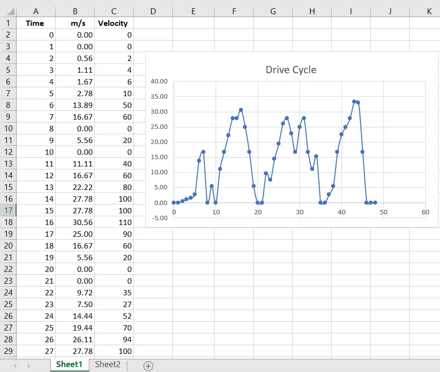
Here for a Drive cycle the required braking energy is calculated for each second of time to slow down or stop the vehicle- Braking Energy Calculation for UDDS Driving Cycle
MATLAB program for the calculation of brake energy.
mass = 1000; % mass of the vehicle in kg
t = velocityandtime(:,1); % time period
v = velocityandtime(:,2); % velocity data in m/s

for i = 1:(length(velocityandtime)-1)

    if v(i)>v(i+1)
        BE(i) = 0.5*mass*(v(i) - v(i+1))^2; % BE stands for brake energy
    end
end
fprintf('Total Brake Energy is %d',sum(BE))
fprintf('Average Brake Energy is %d',mean(BE))

% plotting the results
figure(1)
subplot(2,1,1)
plot(t,v,'linewidth',3,'color','g')
xlabel('Time(s)')
ylabel('Velocity(m/s)')
title('Drivecycle')

subplot(2,1,2)
plot(BE,'linewidth',3,'color','r')
xlabel('Time(s)')
ylabel('Braking Energy')
Results.
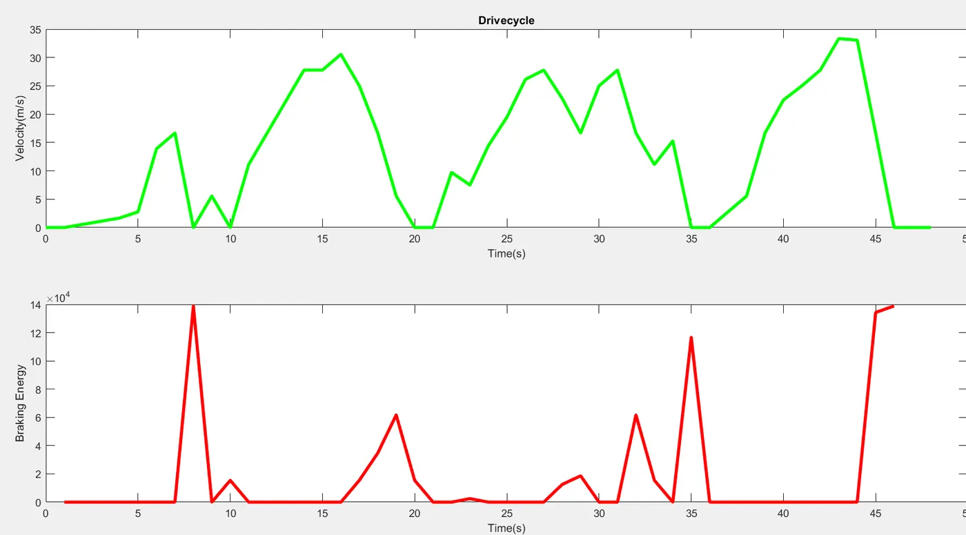
Brake Energy Calculation
Total Brake Energy is 7.823688e + 05
Average Brake Energy is 1.700802e +04>>
2] Why electric motor can’t develop braking torque at high speed similar to starting? How electric and mechanical brakes are coordinated?
Rated speed is the maximum speed the manufacturer says you can run the motor at, for an indefinite period of time, without damaging or overheating. The characteristics you mentioned is specific to DC motors, or to be precise Self Excited DC motors.
Here's a graph showing the torque speed curve of a DC shunt motor.
As you can see, torque of a DC shunt motor decreases as speed increase. Here's a graph for DC series motor. Here the torque decreases exponentially as speed increases. Let's have a look at the favorite motor of the industry, the Induction motor.
As you can see, an Induction motor does not generate max torque at zero speed but at certain speed much like a internal combustion engine. But the thing is, these characteristics are obtained when we run the motor directly from a rated supply. Fortunately, we do not run motors directly from supply. We use Motor Controllers in-between the motor and the supply. Motor Controllers provide lots of advantages over running from from direct supply, Speed Control, regenerative breaking, smooth starting to name a few. Motor controllers emloys one of several control techniques like PWM, space vector modulation, variable frequency etc etc to control motor torque, speed, power output. They can also make a motor produce max torque at any speed below rated speed.
Electric braking or regenerative braking
Hitting the brakes on a car creates kinetic energy. Regenerative braking lets EVs and hybrid vehicles store some of that kinetic energy in the battery to use when you accelerate again. That’s accomplished through the EV motor’s dual-rotation design.
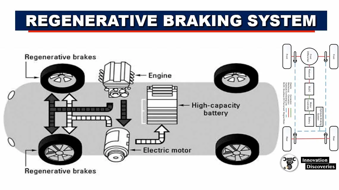
Thus electric motors can’t develop braking torque at high speed similar to starting.
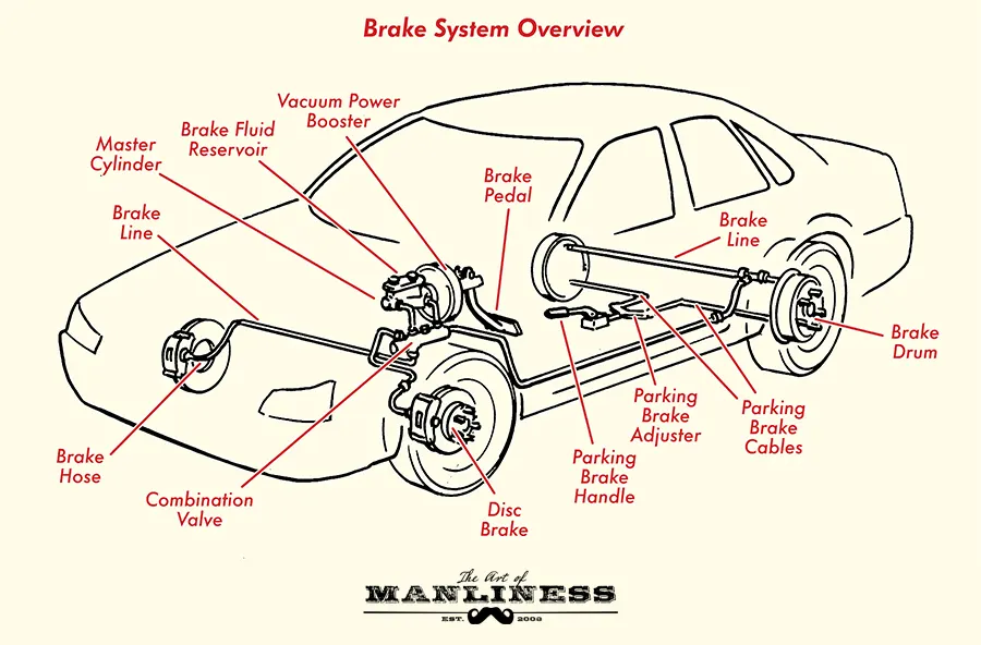
Regenerative braking and mechanical braking both should be use at high speed of the vehicle
Usage of electric and mechanical brakes.
1) low speed only regenerative braking can be used.
2) High speed both mechanical and electric brakes should be used ,control and distribution of load is given by the brake pedal.
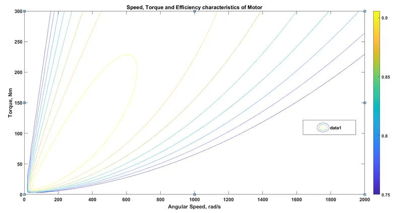
A contour line of a function of two variables is a curve along which the function has a constant value, so that the curve joins points of equal value. It is a plane section of the three-dimensional graph of the function f parallel to the-plane.
1) Copper Losses
Copper losses result from Joule heating and so are also referred to as "I squared R losses", in reference to Joule's First Law. This states that the energy lost each second, or power, increases as the square of the current through the windings and in proportion to the electrical resistance of the conductors.

where I is the current flowing in the conductor and R the resistance of the conductor. With I in amperes and R in ohms, the calculated power loss is given in watts.
Joule heating has a coefficient of performance of 1.0, meaning that every 1 watt of electrical power is converted to 1 Joule of heat. Therefore, the energy lost due to copper loss is.

2) Iron Losses
The iron loss (also known as eddy current and hysteresis loss) depends on the supply voltage and its frequency. As the voltage and frequency are practically constant, this loss remains constant during the operation of an induction motor. Iron loss is further divided into two losses; eddy current loss and hysteresis loss.
To minimize the eddy current loss, the laminated core is used. By laminating the core, the area of the core is decreased, and hence the resistance increases which results in decreases in eddy current.
Hysteresis loss mainly depends on the material used for the core. To minimize hysteresis loss, high-grade silicon steel is used.
3) Windage losses
Windage losses also occur in machines such as turbines and gearboxes.When the shaft rotates, it displaces air. This incurs an expenditure of energy which is called windage loss. it represents a loss of power. Windage loss in rotatory machines occur due to air resistance to the armature. Therefore, in order to even start a motor, the machine needs to overcome friction and windage torque and inertia due to its weight to start rotating. Windage is the churning effect of the rotating armature in the confined space inside the field coils. Even a smooth airflow would take some power to achieve, the very turbulent conditions inside the motor take much more power.
4) Constant or Fixed Losses
Constant losses are those losses which are considered to remain constant over normal working range of Insuction motor. The fixed losses can be easily obtained by performing no-load test on the three phase induction motor.
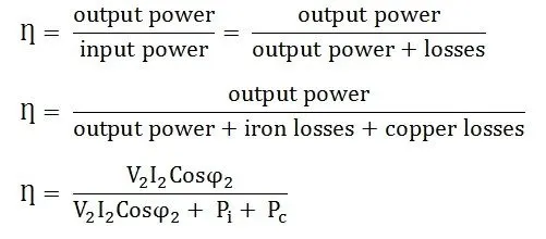
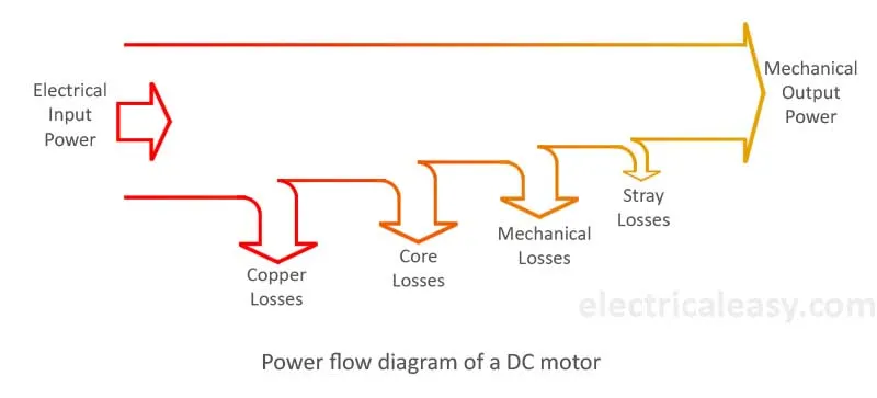
All Motors are model as per the above equation of losses. This above equation is not only applicable for Permanent Magnet DC Motor, but other motors as well like induction motor
MATLAB program for calculating the losses of the EV motor.
Input
clear all
close all
clc

w = linspace(0,1000);
T = linspace(0,250);

% motor constants
kc = 0.2; % for copper loss
ki = 0.008; % for iron loss
kw = 0.00001; % for windage loss
conL = 20; % for constant motor losses

% making mesh
[X,Y] = meshgrid(w,T);
OutputPower = (X.*Y); % Torque x Speed = Power
B = (Y.^2)*kc; % copper loss
C = (X.^3)*kw; % winding loss
D = X*ki; % Iron loss
InputPower = OutputPower + B + C + D + conL;
Z = OutputPower./InputPower;

% Set the efficiencies for which the contours will be plottted
V = [0.70 , 0.75 , 0.80 , 0.82 , 0.85 , 0.87 , 0.89 , 0.90 , 0.92];
box off
grid off
contour(X,Y,Z,V);
xlabel('Speed(rad/s)')
ylabel('Torque(N.m)')
hold on
V = [8000,10000];
contour(X,Y,OutputPower,V);
Output
Results.
Conclusion:
- Calculate the energy required for braking of a defined drive cycle is completed.
- Electric motor can’t develop braking torque at high speed similar to starting , electric and mechanical brakes are coordinated are explained .
- MATLAB program which plots contour of given motor speed, torque and efficiency values. Attach the code as a .m file attach a screenshot of all the plots is done successively.