Week-11 Challenge: Braking
Objective:
- For a defined driving cycle, calculate the energy required for braking.
- Why electric motor can’t develop braking torque at high speed similar to starting? How electric and mechanical brakes are coordinated?
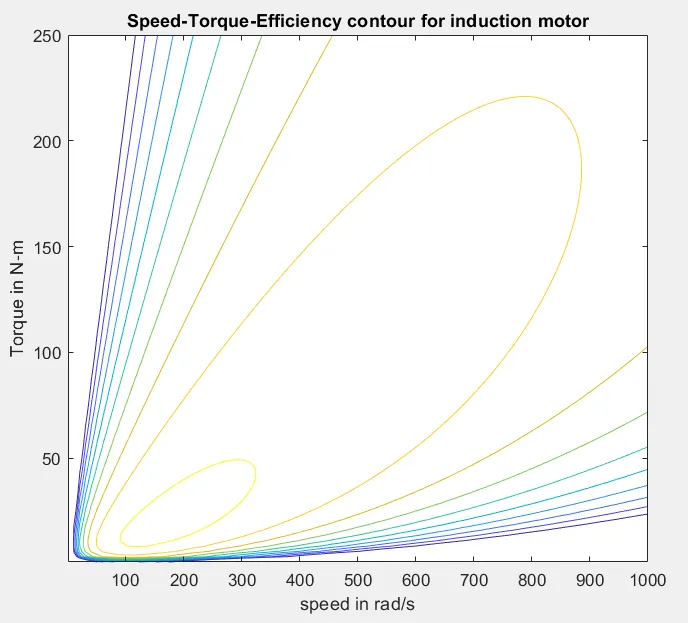
- Make a MATLAB program which plots contour of given motor speed, torque and efficiency values. Attach the code as a .m file attach a screenshot of all the plots.
Study 1:
For a defined driving cycle, calculate the energy required for braking.
Ans:
According to 1st law of thermodynamics,Energy neither be created nor be destroyed but it can be converted from one form to another.
Here,we have taken Urban Dynamometer Driving Schedule(UDDS) cycle for study (data is taken https://www.epa.gov/sites/production/files/2015-10/uddscol.txt).
The moving car posses kinetic energy and Whenever brake pedal is pressed the kinetic energy possesed is gets converted into the heat energy.and the braking energy required to stop the car is calculated by
BE = 1/2*m*v^2
Where,
BE = braking enrgy
m = mass of vehicle in kg (here,m=1000 kg)
v = velocity of vehicle in m/s
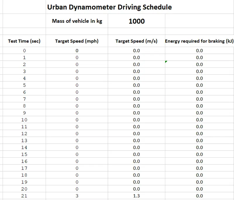
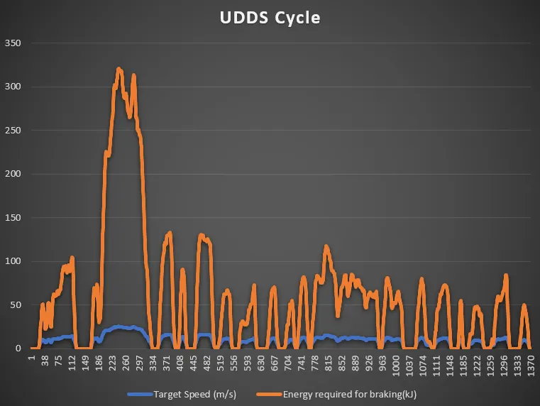
Here,maximum velocity atained is 25.3 m/s
BE = 1/2*1000*25.3^2
= 320.045 kJ
Therefor,braking energy required stop vehicle at 25.3 m/s is 320.045 kJ
drive link :https://drive.google.com/file/d/1xoKFPFMuMiwszfEk-iHoHubrZI4NSRLl/view?usp=sharing
Study 2:
Why electric motor can’t develop braking torque at high speed similar to starting? How electric and mechanical brakes are coordinated?
Ans:
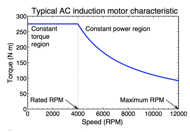
In electric motors, maximum torque is produced from the get-go. As a current flow through the electric motor, a related electrical charge causes an armature to rotate. These rotations within an internal magnetic field cause something called a back-EMF (electromotive force) which opposes the supply voltage. Imagine back-EMF to be the equivalent of a natural braking force, much like in IC engines.
The net overall force being applied to the wheels is therefore the difference between the supply voltage and the EMF. The back-EMF is proportional to speed, therefore the higher the speed, the smaller the net overall force is. This explains why the torque curve begins to diminish.
How electric and mechanical brakes are coordinated?
Mechanical braking is provided in an electric vehicle to stop and decelerate the vehicle whenever necessary. The brake system shall be disc or drum brake.
In a traditional braking system, brake pads produce friction with the brake rotors to slow or stop the vehicle. Additional friction is produced between the slowed wheels and the surface of the road. This friction is what turns the car's kinetic energy into heat. With regenerative brakes, on the other hand, the system that drives the vehicle does the majority of the braking. When the driver steps on the brake pedal of an electric or hybrid vehicle, these types of brakes put the vehicle's electric motor into reverse mode, causing it to run backwards, thus slowing the car's wheels. While running backwards, the motor also acts as an electric generator, producing electricity that's then fed into the vehicle's batteries.
There are two important problems in designing the regenerative braking system. First, how to distribute the total braking forces required between the regenerative brake and the mechanical brake in order to recover kinetic energy of the vehicle as much as possible; second, how to distribute the total braking forces on the front and rear axles so as to minimize the stopping distance and conserve the vehicle stability. Usually, regenerative braking is effective only for the driven axle.
Series Braking:
The series braking system with optimal feel consists of a braking controller that controls the braking forces on the front and rear wheels. The purpose of this strategy is to minimize the stopping distance and optimize the driver’s feel. The shortest braking distance and good braking feel require the braking forces on the front and rear wheels to follow the ideal braking force distribution. braking force on the rear wheels (driven axle) is composed of two parts: regenerative braking force and mechanically frictional braking force. When the braking force demanded for rear axle is less than the maximum braking force that the electric motor can produce, only electrically regenerative braking will apply. But when the commanded baking force is greater than the available regenerative braking force, the electric motor will operate its maximum braking torque, and the remaining braking force is provided by mechanical braking system.
Parallel Braking:
The parallel brake system includes both an electrical (regenerative) brake and a mechanical brake, which produce braking forces in parallel and simultaneously. The operating principal is, in which regenerative braking is applied only to the driven axle. The parallel brake system has a conventional mechanical braking which has a fixed ratio of braking forces distribution on the front and rear wheels. Regenerative braking adds additional braking force to the driven axle. The mechanical braking forces on the front and rear axles are proportional to the hydraulic pressure in the master cylinder. Because the regenerative braking force available is a function of motor speed and because almost no kinetic energy can be recovered at low motor speed, the regenerative braking force at high vehicle deceleration is designed to be zero so as to maintain braking balance. When the demanded deceleration is less than this deceleration, regenerative braking is effective.
Study 3:
Make a MATLAB program which plots contour of given motor speed, torque and efficiency values. Attach the code as a .m file attach a screenshot of all the plots
Code:
clear all
close all
clc

% x corrosponds to motor speed in rad/s
% y corrosponds to torque in N-m
x = linspace(1,1000);
y = linspace(1,250);

% define motor loss constant
k_c = 0.2; % copper loss constant
k_i = 0.008;% iron loss constant
k_w = 0.00001;% windage loss constant
conL = 20; % constant motor loss

% make mesh
[speed,Torque]= meshgrid(x,y);
OutputPower = (speed.*Torque);% speed*torque = power

B = (Torque.^2).*k_c;% Cu loss
C = speed.*k_i;% iron loss
D = (speed.^3)*k_w;%windage loss

InputPower = OutputPower + B + C + D + conL;

Efficiency = OutputPower./InputPower;

% set the efficiencies to plot contour
v = linspace(0.70,0.95,10);

contour(speed,Torque,Efficiency,v);
title('Speed-Torque-Efficiency contour for induction motor')
xlabel('speed in rad/s')
ylabel('Torque in N-m')
hold on
Explanation:
1.take the speed between 1 to 1000 rad/s and torque between 1 and 250 N-m using 'linspace' command.
2.define the constant for various core losses and calculate core losses.Add Output power and various losses to calculate Inputpower.
3.Using 'meshgrid' command create 2-D grid of speed and torque.
4.take the 10 values of efficiencies between 0.7 and 0.95 and create contour of speed,torque,efficiency using contour command
Plot: