Week 11 Challenge – BRAKING
Week 11 Challenge – Braking
Aim –
- To calculate energy required for braking for a defined Drive Cycle.
- To understand why electric motors cannot develop braking torque at higher speed similar to starting & also compare mechanical & electrical breaking.
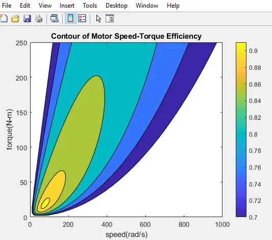
- To create MATLAB program which plots the contour for the given motor speed, torque & efficiency values.
- Calculate energy required for braking for a defined Drive Cycle.
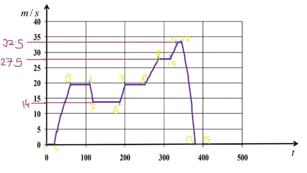
To calculate braking energy, we consider 9 points i.e. up to 300 sec. of Drive cycle & calculate braking energy during acceleration & deceleration.
A Driving Cycle is a series of data points representing the speed of a vehicle vs. time. Driving cycles are produced by different countries and organisations to access the performance of the vehicles in various ways, as for example fuel consumption and polluting emissions.
Formulas used in Calculations –
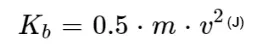
Where,
m = Mass of the vehicle (Payload + Kerb Weight) = 1000 Kg.
v = Velocity in Km/h
In case of Braking the high speed is reduced to low speed,
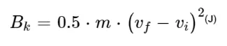
Vf = Final Velocity in m/s.
Vi = Initial Velocity in m/s.
By substituting the values in the above formulas we can get the output in the form of Joules or Kilojoules.
Total braking energy = Kinetic Energy of the Vehicle
= K.E. (Due to linear motion) + K.E. (Due to rotational motion)
But here we consider only Kinetic energy due to linear motion for simplicity
Let the mass of the vehicle (m) = 1000kg.
Now take K.E. between point 1 & point 2
Braking Energy = (K.E.)2 – (K.E.)1 = 0 ……… (As velocity is same = 0 m/s)
Between Point 2 & Point 3
Braking Energy = (K.E.)3 – (K.E.)2
= (0.5*M*V2) * 3 - (0.5*M*V2) * 2
= (0.5*1000*202) - (0.5*1000*02)
= 2,00,000 J
= 200 KJ
Between Point 3 & Point 4
Braking Energy = (K.E.)4 – (K.E.)3 = 0 ……(As Velocity is same)
Between Point 4 & Point 5
Braking Energy = (K.E.)5 – (K.E.)4
= (0.5*M*V2) - (0.5*M*V2)
= (0.5*1000*142) - (0.5*1000*202)
= 1,02,000 J
= - 102 KJ …. (Negative sign represents Deceleration)
Between Point 5 & Point 6
Braking Energy = (K.E.)6 – (K.E.)5 = 0 ……(As velocity is same)
Between Point 6 & Point 7
Braking Energy = (K.E.)7 – (K.E.)6
= (0.5*M*V2) - (0.5*M*V2)
= (0.5*1000*202) - (0.5*1000*142)
= 1,02,000 J
= 102 KJ
Between Point 7 & Point 8
Braking Energy = (K.E.)8 – (K.E.)7 = 0 ……(As velocity is same)
Between Point 8 & Point 9
Braking Energy = (K.E.)9 – (K.E.)8
= (0.5*M*V2) - (0.5*M*V2)
= (0.5*1000*27.52) - (0.5*1000*202)
= 1,78,125 J
= 178.12 KJ
Between Point 9 & Point 10
Braking Energy = (K.E.)10 – (K.E.)9 = 0 ……(As velocity is same)
Thus Net Braking Energy during Drive Cycle (0 + 200 + 0 + (-102) + 0 + 178.12 + 0)KJ
= 378.12 KJ
So, we required 378.125 KJ of Braking Energy up to 300 Sec. of Drive cycle.
- why electric motors cannot develop braking torque at higher speed similar to starting & also compare mechanical & electrical breaking.
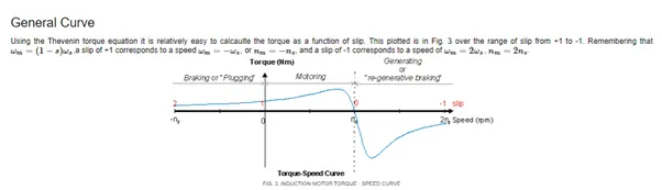
We know that during acceleration the motor requires an initial torque to raise from 0 to higher speed. But on the other hand during deceleration, the motor which is already running at higher speed & also at higher torque will be able to develop further torque & the above curve explains it.
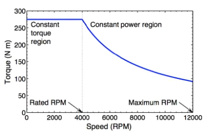
Vehicle at low speed has constant torque region where higher acceleration is possible, at high speed it becomes constant power which is easy to get to top speed. For braking when compared with forward motoring, the power required varies, at peak the torque required for forward motoring isn’t equal to reverse motoring, this is why electric motors can’t develop braking torque at high speed similar to starting.
Current flows through the electric motor, a related electric charge causes armature to rotate. These rotations within an internal magnetic field cause something called back- emf (electromotive force) which opposes the supply voltage. Imagine back-emf to be equivalent of natural braking force, much like an IC Engine.
From the above graph Speed & Torque of an electric motor is plotted.
At 0 speed the torque is so high & it is called as constant torque region. In this region the torque produced is constant for typical speed of motor operation.
At Rated speed the torque curve is gradually dropped & enters the constant power region & the braking torque produced is very low so the motor is not be able to create maximum torque while braking.
Conventional Braking –
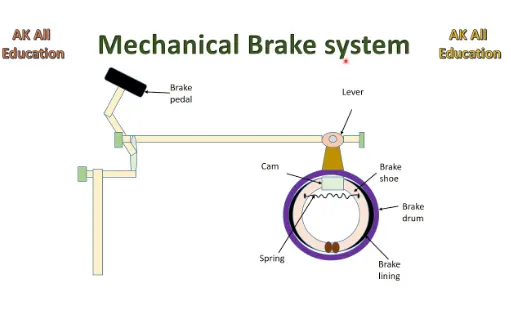
Conventional brakes consist of basic hydraulic system which sends fluid to each wheel when the brake pedal is applied. The system utilizes the combination of mechanical components to increase the force on the drums or the rotors when you press the brake pedal to activate the brakes, bringing the vehicle to a stop.
Regenerative Braking –
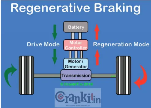
Electric motors when used in reverse function as generators and then it will convert mechanical energy into electrical energy. Vehicles propelled by electric motors use them as generators when using regenerative braking, breaking by transferring mechanical energy from the wheels to an electrical load.
These 2 brakes can be combined for better optimization; in which they are –
Parallel Regenerative Braking –
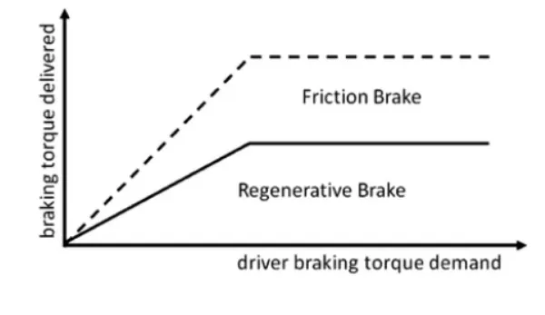
In parallel braking the frictional brakes and regenerative braking operate together. This has lower recuperation ratio i.e. Regenerative Braking is absorbed less.
It includes electrical & mechanical braking system which produces braking force in parallel & simultaneously this kind of braking system has a conventional mechanical braking which has fixed ratio if brake force distribution on front & back wheel.
Series Braking System –
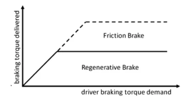
Series braking system consist of brake controller which controls the braking forces on the front & rear wheel. The purpose of this strategy to minimize stopping distance & give optimized feel to driver & this requires brake force on the front wheel & rear wheel to follow ideal brake force distribution.
The main principle of series braking system is to recover the braking energy as much as possible in the condition of meeting the total breaking force for a given deceleration.
The regenerative braking starts to operate before the frictional braking & the regeneration is increased when compared with parallel braking.
- To create MATLAB program which plots the contour for the given motor speed, torque & efficiency values
While, motor works there are various types of losses –
- Copper losses.
- Iron losses.
- Windage losses.
- Constant losses.
- Copper losses –
Copper losses are given by I2.R
Where, R = Armature resistance.
And if we say Torque is proportional to current then, the copper loss is considered as Kc. T2
Where, Kc is to take care of resistance of brushes & also to take care of flux and its effect.
Hence Copper Losses = Kc. T2
2. Iron losses –
Iron losses are magnetic losses denoted by Ki. W, where Ki is the factor based on magnetic field effect.
3. Windage losses –
These are the mechanical or friction Windage losses. This is based on size and shape of the motor & the Windage losses that the motor is going to experience hence the Windage losses = Kw. W3
4. Constant losses –
This is denoted by C.
5. Total losses –
The total losses are given by,
Total Losses = Kc. T2 + Ki. W + Kw. W3 + C.
clear all

close all

clc

% Input Arrays

speed = linspace(0,1000);

torque = linspace(0,250);

% Input for motor loss constants

k_c = 0.2; %Copper Loss

k_i = 0.008; %Iron Loss

k_w = 0.0001; %Windage Loss

constant = 20;


%Creating Meshgrid

[X,Y] = meshgrid(speed,torque);

Output_power = (X.*Y);

cu_loss = (Y.^2)*k_c;

iron_loss = k_i*X;

windage_loss = k_w*(X.^3);

Input_power = Output_power + cu_loss + iron_loss + windage_loss + constant;

Efficiency = Output_power./Input_power;

%Range of Values

V = [0.70, 0.75, 0.80, 0.85, 0.89, 0.91, 0.93];

% Plotting Speed-Torque Efficinecy

box off

grid off

contourf(speed,torque,Efficiency,V);

colorbar

xlabel("speed(rad/s)");

ylabel("torque(N-m)");

zlabel(Efficiency);

title("Contour of Motor Speed-Torque Efficiency")