Week 11 Challenge
| Aim: - Based on the following data pile foundation is need to be design for following aspects: | |
| 1. Design load calculation to be done based on salb. Here data given as slab based bridge | |
| 2. For live load calculation Class 70R & class A type to be considered | |
| 3. ULS,SLS & Quasi permanaent baesd combination & checks to be done. | |
| 4. Based on the combination pile foundation to be done. | |
| 5. Rebar quantatiesto be estimated based on reinforcement detail. | |
| Inroduction and explaination | |
| Basic design data | |
| Given data | |
| Span and cross-section | |
| Right span | |
| C/Cof exp joint | 28m |
| C/C of bearing | 22.652m |
| Distance of beraing to expansion joint | 0.5m |
| C/s | |
| Total deck width | 12m |
| Carriageway width | 8.5m |
| Width of crash barrier | 0.5m |
| Width of footh path | 1.5m |
| SUPERSTRUCTURE DETAIL | |
| wearinng coat thickness | 0.065m |
| Type of super structure | RCC |
| LEVELS | |
| Height of abutment | 4m |
| Clear cover for foundation | 75mm |
| scour depth | 3.5m |
| MATERIAL USED | |
| Grade of concrete (Fck) | M35 |
| Design strength of concrete (Fcd) | 15.63 Mpa |
| Grade of steel (Fy) | Fe500 |
| Design strength of steel (Fyd) | 434.8 Mpa |
| Coeff of thermal expansion of concrete | 1.2 E^05/degree C |
| Shrinkage strain of concrete | 2 E^4 |
| Modulus of elasticity of steel | 200000 Mpa |
| Modulus of elasticity of concrete | 32000 Mpa |
| Mean axial tensile strength of concrete fct | 2.8 Mpa |
| Density of concrete (RCC) | 2.5 t/m^3 |
| Density of wearing coat | 2.2 t/m^3 |
| SOIL PARAMETER | |
| Density of dry backfill | 2 t/m^3 |
| Density of submerged backfill | 1 t/m^3 |
| Type of soil | Medium soil |
| Coeff of friction | 0.5 |
| k(active) | 0.33 |
| Vertical capacity | 300 t |
| Horizotal capacity | 40 t |
| DEAD LOAD | |
| Total weight of superstructure | 0 t |
| DL reaction of right span | 730 t |
| Total reaction on abutment | 365 t |
| Unbalanced Long. Moment | 0 tm |
| Tansverse ecc. Of DL from pier c/l | 0 m |
| Trans. Moment due to unbalanced DL | 0 tm |
| SIDL (except WC) | |
| Weight of crash barrier | 1 t/m |
| Weight of crash barrier | 30 t |
| Total reaction on abutment | 15 t |
| Total long. Moment | 0 tm |
| Transverse ecc.of CB | 0 m |
| Transverse moment of CB | 0 tm |
| SIDL (WC) | |
| Load intensity due to WC | 0.22 t/m^2 |
| DL of WC | 36.30 t |
| Total reaction on abutment | 18.15 t |
| Unbaalanced Long. Moment | 0 tm |
| Transverse ecc. Of WC | 0 m |
| Transverse moment due to unbalanced WC | 0 tm |
| SUMMARY | ||||||
| Force at bearing level | ||||||
| Load case | Load P | Load (min) | ML | MT | HL | HT |
| t | t | tm | tm | t | t | |
| DL | 365 | 365 | 0 | 0 | 0 | 0 |
| SIDL | 15 | 15 | 0 | 0 | 0 | 0 |
| SIDL (WC) | 36 | 36 | 0 | 0 | 0 | 0 |
| Force at abutment bottom level | ||||||
| Load case | Load P | Load (min) | ML | MT | HL | HT |
| t | t | tm | tm | t | t | |
| DL | 365 | 365 | 0 | 0 | 0 | 0 |
| SIDL | 15 | 15 | 0 | 0 | 0 | 0 |
| SIDL (WC) | 36 | 36 | 0 | 0 | 0 | 0 |
| Force at pile cap bottom level | ||||||
| Load case | Load P | Load (min) | ML | MT | HL | HT |
| t | t | tm | tm | t | t | |
| DL | 365 | 365 | 0 | 0 | 0 | 0 |
| SIDL | 15 | 15 | 0 | 0 | 0 | 0 |
| SIDL (WC) | 36 | 36 | 0 | 0 | 0 | 0 |
| ABUTMENT CAP | |
| Rectangular part | |
| Length (T-T) | 12 m |
| Length (L-L) | 2.65 m |
| Height | 0.775 m |
| Volume | 24.645 m^3 |
| Weight | 61.61 t |
| TRAPEZOIDAL PART | |
| Top length (T-T) | 11 m |
| Bottom Length (T-T) | 11 m |
| Width at top | 2.65 m |
| Width at bottom | 2.65 m |
| Height | 0.825 m |
| Volume | 24.05 m^3 |
| Weight | 60.12 t |
| Total weight of pier cap | 121.73 t |
| ABUTMENT SHAFT | |
| Dimension along traffic | 1 m |
| Dimension perpendicular to length | 11 m |
| Area-rectangular part | 11 m^2 |
| Height | 3.40 m |
| Volume | 37.40 m^3 |
| Area-semicircular | 0.39 m^2 |
| Height | 3.40 m |
| Volume | 2.67 m^3 |
| Weight | 100.17 t |
| Total weight of substructure | 221.91 t |
| FOUNDATION | |
| Type of foundaion, Pile | pile |
| Pile cap | |
| Length | 4.3 m |
| Length, L-L | 12.3 m |
| Depth | 1.5 m |
| Volume | 79.335 m^3 |
| Total weight of foundation | 198.34 t |
| EARTH PRESSURE LOADS | |
| Active & Passive EP Coef | |
| Angle of shear resisrance | 30 degree |
| Density of dry backfill | 2 t/M^3 |
| Density of submerged backfill | 1 t/m^3 |
| Net SBC | 25 t/m^3 |
| Gross SBC (LWL) | 33.42 t/m^3 |
| Gross SBC (HFL) | 27 t/m^3 |
| Live load surcharge | 1.2 m |
| Type of soil | mdium soil |
| Coefficient of friction | 0.5 |
| Alpha | 90 |
| Beta | 0 |
| Delta | 20 |
| Ka | 0.33 |
| Kah | 0.301 |
| Kav | 0.135 |
| Kp | 6.105 |
| Kph | 5.738 |
| Kpv | 2.088 |
| NORMAL CASE-LWL | |
| Force due to earth pressure | 99 t |
| Lever arm, 0.42H | 2.1 m |
| Moment, ML | 207.9 tm |
| LIVE LOAD | |
| One span loaded | |
| 1 lane 70R wheeled | |
| Vertical reaction on abutment | 60.49 t |
| Braking force | 21.78 t |
| Change in reaction due to braking force | 3.65 t |
| Maximum vertical force on abutment | 64.14 t |
| Minimum vertical force on abutment | 56.84 t |
| Longitudinal Moment | 0.00 tm |
| Total horizontal force at bearing level | 10.89 t |
| Total horizontal force (Longitudinnal) | 10.89 t |
| Transverse eccentricity | 2.91 m |
| Transverse moment | 175.72 tm |
| 1 Lane Class A | |
| Load in left span | 0 t |
| Load in right span | 34.29 t |
| Vertical reaction on abutment | 34.29 t |
| Braking force | 10.93 t |
| Change in reaction due to braking force | 1.83 t |
| Maximum vertical force on abutment | 36.12 t |
| Minimum vertical force on abutment | 32.46 t |
| Longitudinal Moment | 0.00 tm |
| Total horizontal force at bearing level | 5.46 t |
| Total horizontal force (Longitudinnal) | 5.46 t |
| Transverse eccentricity | 4.20 m |
| Transverse moment | 144.02 tm |
| 3 Lane Class A | |
| Load in left span | 0 t |
| Load in right span | 102.87 t |
| Vertical reaction on abutment | 102.87 t |
| Braking force | 13.66 t |
| Change in reaction due to braking force | 2.29 t |
| Maximum vertical force on abutment | 105.16 t |
| Minimum vertical force on abutment | 100.58 t |
| Longitudinal Moment | 0.00 tm |
| Total horizontal force at bearing level | 6.83 t |
| Total horizontal force (Longitudinnal) | 6.83 t |
| Transverse eccentricity | 0.70m |
| Transverse moment | 72.01 tm |
| 1Lane 70R W + 1 Lane Class A | |
| Load in left span | 0 t |
| Load in right span | 94.78 t |
| Vertical reaction on abutment | 94.78 t |
| Braking force | 24.51 t |
| Change in reaction due to braking force | 4.11 t |
| Maximum vertical force on abutment | 98.89 t |
| Minimum vertical force on abutment | 90.67 t |
| Longitudinal Moment | 0.00 tm |
| Total horizontal force at bearing level | 12.26 t |
| Total horizontal force (Longitudinnal) | 12.26 t |
| Transverse eccentricity | 2.905 m |
| Transverse moment | 155.99 tm |
| SUMMARY | ||||||
| Load Case | Pmax | Pmin | ML | MT | HL | HT |
| t | t | tm | tm | t | t | |
| 1-70R | 64.14 | 56.84 | 0 | 175.72 | 10.89 | 0 |
| 1-CL-A | 36.12 | 32.46 | 0 | 144.02 | 5.46 | 0 |
| 3-CL-A | 105.16 | 100.58 | 0 | 72.01 | 6.83 | 0 |
| 1-70R+CLA | 98.89 | 90.67 | 0 | 155.99 | 12.26 | 0 |
| Force at pile cap bottom level | ||||||
| Load Case | Pmax | Pmin | ML | MT | HL | HT |
| t | t | tm | tm | t | t | |
| LL1 | 105.16 | 100.58 | 44.39 | 72.01 | 6.83 | 0 |
| LL2 | 98.89 | 90.67 | 79.66 | 155.99 | 12.26 | 0 |
| CALCULATION OF LIVE LOAD INTENSITY (28 m span) | ||
| 1.0) Eff. Width of tyres and load distributionn for different vehicular loadings | ||
| A) Class 70R Vehical | ||
| Load on one tyre | 200/4 | 50 kN |
| Max. tyre pressure | 527.3 | kN/m^2 |
| Contact area | 50/527.3 | 0.094822682 |
| Width of contact | 410-50 | 360 mm |
| Breadth | 948.23/36 | 263.4 mm |
| Contact area | 360mm*263mm | |
| Min. clear distance from kerb to the edge of the end wheel = 1200 mm | ||
| Effective width= Aa(1-a/Io)+b1(Refer annex B-3.2(2) of IRC:112-2011) | ||
| Io= Effective span | 28 m | |
| a = The distance of c.g of the concentrated load from nearere support | 14 m | |
| Wearing coat/ filling thickness | 0.075 m | |
| Thickness of deck slab | 1.00 m | |
| Contact width of tyre ii a direction perpendicular to the span | 0.36 m | |
| b1 | 0.51 m | |
| b= width of the slab | 12 m | |
| b/Io | 0.429 m | |
| a(Refer annnex B-3.2(2)of IRC:112-2011) | 1.5 m | |
| Effective width= Aa(1-a/Io)+b1(Refer annex B-3.2(2) of IRC:112-2011) | 7.23 m | |
| >2.38 m | ||
| Width of crash barrier | 0.5 m | |
| Clear distance between kerb and wheel | 1.2 m | |
| Wheel dimension perp. To span | 0.41 m | |
| Distance from outer edge of kerb to c.g of wheel | 1.905 m | |
| Effective width for design | 8.44 m | |
| Length of slab in traffic direction | 24 m | |
| Dispersion along span direction(Refer annex B-3.3 of IRC:112-2011) | 3.24 m | |
| > | ||
| Distance between the axles in the dir. Of traffic | 1.22 m | |
| Dispersion width fro calculation | 3.633 m | |
| Total load | 400.0 Kn | |
| Dispersion area | 30.67 m^2 | |
| Load per unit | 13.04 kN/m^2 | |
| Impact factor | 1.21 | |
| Load per unit area with impact | 15.8 kN/m^2 | |
| (II)AXLE-"m" | ||
| Contact size | 360mm*263mm | |
| Min. clear distance from kerb to the edge of the end wheel = 1200 mm | ||
| Effective width= Aa(1-a/Io)+b1(Refer annex B-3.2(2) of IRC:112-2011) | ||
| Io= Effective span | 28 m | |
| a = The distance of c.g of the concentrated load from nearere support | 14 m | |
| Wearing coat/ filling thickness | 0.075 m | |
| Thickness of deck slab | 1 m | |
| Contact width of tyre ii a direction perpendicular to the span | 0.36 m | |
| b1 | 0.51 m | |
| b= width of the slab | 12 m | |
| b/Io | 0.80 m | |
| a(Refer annnex B-3.2(2)of IRC:112-2011) | 2.08 | |
| Effective width= Aa(1-a/Io)+b1(Refer annex B-3.2(2) of IRC:112-2011) | 8.31 m | |
| 2.38 m | ||
| Width of crash barrier | 0.5 m | |
| Clear distance between kerb and wheel | 1.2 m | |
| Wheel dimension perp. To span | 0 m | |
| Distance from outer edge of kerb to c.g of wheel | 1.7 m | |
| Effective width for design | 8.24 m | |
| Length of slab in traffic direction | 28 m | |
| Dispersion along span direction ((refer annex B-3-3 of IRC: 112-2011)) | 2.41 m | |
| > | ||
| Distance between axel in traffic direction | 1.22 m | |
| Dispersion width calculation | 3.63 m | |
| Total load | 400.0 kN | |
| Dispersion area | 29.92 m^2 | |
| Load per unit area | 13.37kN/m^2 | |
| Impact factor (Refer CL.208 of IRC:6-2010) | 1.21 | |
| Load per unit area with impact | 16.18 kN/m^2 | |
| (III) Axle-"n" | ||
| Load on single tyre=200/8 | 25 kN | |
| Max. tyre pressure | 527.3 kN/m^2 | |
| Area of conntact for tyre | 2500/527.3 | 47411 mm^2 |
| Width of contact for tyre=230-50= | 180 mm | |
| Breadth of tyre | 474.11/18 | 263.40 mm |
| Contact size | 180mm*263mm | |
| Min clear sistance from kerb to the edge of the end wheel | 1200 mm | |
| Effective width=aa(1-a/Io)+b1(Reffer annex B.-3.2(2) of IRC:112-2011) | ||
| Io= Effective span | 28 m | |
| a=The diatance of c.g of the concentrated load from nearer support | 14 m | |
| Wearing coat/filling thickness | 0 m | |
| Thickness of deck slab | 1 m | |
| Contact width of the tyre ii a direction perpendicular to the span | 0.18 m | |
| b1 | 0.18 m | |
| b= width of the slab | 12 m | |
| b/Io | 0.429 m | |
| a(Refer annex B.3.2(2) od IRC:112-2011) | 2.60 m | |
| Effective width | 9.93 m | |
| >2.56 m | ||
| Width of crach barrier | 0.5 m | |
| clear disttance between kerb and wheel | 1.2 m | |
| Wheel dimension perp. To span | 0.23 m | |
| Distaance from outer edge to kerb to c.g of wheel | 1.815 m | |
| Effective width for design | 9.34 m | |
| Length of slab in traffic direction | 15 m | |
| Dispersion along the span direction ((Refer annex B.3.3 of IRC:112-*2011)) | 4.634 m | |
| Distance between axel in traffic direction | 1.22 m | |
| Dispersion width for calculation | 5.85 m | |
| Total load | 400.0 kN | |
| Dispersion area | 54.68 m^2 | |
| Load per unitt area | 7.3 kN/m^2 | |
| Impact factpr(Refer Cl.208 of IRC:6-2010) | 1.21 | |
| Load per unit area with impact | 8.85 kn/m^2 | |
| B) Class-A Vehical | ||
| Min clear sistance from kerb to the edge of the end wheel | 150 mm | |
| Effective width=aa(1-a/Io)+b1(Reffer annex B.-3.2(2) of IRC:112-2011) | 1200 mm | |
| Io= Effective span | 28 m | |
| a=The diatance of c.g of the concentrated load from nearer support | 14 m | |
| Wearing coat/filling thickness | 0.1 m | |
| Thickness of deck slab | 1 m | |
| Contact width of the tyre ii a direction perpendicular to the span | 0.5 m | |
| b1 | 0.65 m | |
| b= width of the slab | 12 m | |
| b/Io | 0.8 m | |
| a(Refer annex B.3.2(2) od IRC:112-2011) | 2.08 m | |
| Effective width | 8.45 m | |
| >1.8 m | ||
| Width of crach barrier | 0.5 m | |
| clear disttance between kerb and wheel | 0.15 m | |
| Wheel dimension perp. To span | 0.5 m | |
| Distaance from outer edge to kerb to c.g of wheel | 0.9 m | |
| Effective width for design | 6.93 m | |
| Length of slab in traffic direction | 24 m | |
| Dispersion along the span direction ((Refer annex B.3.3 of IRC:112-*2011)) | 2.40 m | |
| Distance between axel in traffic direction | >1.2 m | |
| Dispersion width for calculation | 3.6 m | |
| Total load | 228 kN | |
| Dispersion area | 24.96 m^3 | |
| Load per unitt area | 9.1 kN/m^2 | |
| Impact factpr(Refer Cl.208 of IRC:6-2010) | 1.21 | |
| Load per unit area with impact | 11.11 kN/m | |
| Class 70R tracked vehical | ||
| Total load | 700 kN | |
| Length of vehicall in span direction | 4.57 m | |
| Load per meter run | 153.2 kN/m | |
| Dimension of tyre in the direction perpendicular to span | 0.85 m | |
| Min clear sistance from kerb to the edge of the end wheel | 2.05 m | |
| Effective width=aa(1-a/Io)+b1(Reffer annex B.-3.2(2) of IRC:112-2011) | ||
| Io= Effective span | 28 m | |
| a=The diatance of c.g of the concentrated load from nearer support | 14 m | |
| Wearing coat/filling thickness | 0.1 m | |
| Thickness of deck slab | 1 m | |
| Contact width of the tyre ii a direction perpendicular to the span | 0.85 m | |
| b1 | 1 m | |
| b= width of the slab | 12 m | |
| b/Io | 0.80 m | |
| a(Refer annex B.3.2(2) od IRC:112-2011) | 2.05 m | |
| Effective width | 8.80 m | |
| >2.05 m | ||
| Width of crach barrier | 0.5 m | |
| clear disttance between kerb and wheel | 1.2 m | |
| Wheel dimension perp. To span | 0.85 m | |
| Distaance from outer edge to kerb to c.g of wheel | 2.123 m | |
| Effective width for design | 8.58 m | |
| Total load | 153.2 t/m | |
| Dispersion width | 8.58 m | |
| Load per unitt area | 17.9 kN/m^2 | |
| Impact factpr(Refer Cl.208 of IRC:6-2010) | 1.1 | |
| Load per unit area with impact | 19.65 kN/m^2 | |
| Vehical | Load (kN/m2) | |
| 70R-Axel I | 15.783 | |
| 70R-Axel m | 16.176 | |
| 70R-Axle n | 8.852 | |
| Class A | 11.105 | |
| 70R-Track | 19.649 | |
| Design LL intensity for analysis | 16.65 kN/m^2 |
| Combination of load for design of foundation | ||||||||||||||
| Footing bottom level | ||||||||||||||
| Maximum reaction case | ||||||||||||||
| Load | Unfactored | Factor | factored | |||||||||||
| Pmax | Pmin | ML | MT | HL | HT | Pmax | Pmin | ML | MT | HL | HT | |||
| t | t | tm | tm | t | t | t | t | tm | tm | t | t | |||
| DL+Superstructure | 365 | 365 | 0 | 0 | 0 | 0 | 1.35 | 492.75 | 492.75 | 0 | 0 | 0 | 0 | |
| SIDL (Without WC) | 15 | 15 | 0 | 0 | 0 | 0 | 1.35 | 20.25 | 20.25 | 0 | 0 | 0 | 0 | |
| Wearing Coat | 36.3 | 36.3 | 0 | 0 | 0 | 0 | 1.75 | 63.53 | 63.53 | 0 | 0 | 0 | 0 | |
| LL-1 | 105.16 | 100.58 | 44.39 | 72.01 | 6.83 | 0 | 1.5 | 157.74 | 150.87 | 66.58 | 108.01 | 10.24 | 0 | |
| LL-2 | 98.89 | 90.67 | 79.66 | 155.99 | 12.26 | 0 | 1.5 | 148.33 | 136.01 | 119.49 | 233.98 | 18.38 | 0 | |
| Weight of substructure | 221.91 | 221.91 | 0 | 0 | 0 | 0 | 1.35 | 299.57 | 299.57 | 0 | 0 | 0 | 0 | |
| Weight of soil above ftg | 0 | 0 | 0 | 0 | 0 | 0 | 1.35 | 0 | 0 | 0 | 0 | 0 | 0 | |
| Pilecap weight | 198.34 | 198.34 | 0 | 0 | 0 | 0 | 1.35 | 267.76 | 267.76 | 0 | 0 | 0 | 0 | |
| Total forces (LL1) | 801.7 | 797.12 | 44.39 | 72.01 | 6.83 | 0 | Total forces (LL1) | 1112.59 | 1105.73 | 66.58 | 108.01 | 10.24 | 0 | |
| Total forces (LL2) | 795.43 | 787.21 | 79.66 | 155.99 | 12.26 | 0 | Total forces (LL2) | 1103.19 | 1090.86 | 119.49 | 233.98 | 18.38 | 0 | |
| Unfactored | Pmax | Pmin | ML | MT | HL | HT | factored | Pmax | Pmin | ML | MT | HL | HT | |
| Total forces (LL1) | 801.7 | 797.12 | 44.39 | 72.01 | 6.83 | 0 | Total forces (LL1) | 1112.59 | 1105.73 | 66.58 | 108.01 | 10.24 | 0 | |
| Total forces (LL2) | 795.43 | 787.21 | 79.66 | 155.99 | 12.26 | 0 | Total forces (LL2) | 1103.19 | 1099.86 | 119.49 | 233.98 | 18.38 | 0 | |
| Pile check unfactored | |||||||||
| Length of pile cap along X= | 12.3 m | ||||||||
| Length of pile cap along Y= | 5.1 m | ||||||||
| Thickness of pile cap | 1.5 m | ||||||||
| Area of pile cap | 62.73 m^2 | ||||||||
| Density of concrete | 25 kN/m^2 | ||||||||
| Weight of pile cap | 2352 kN | ||||||||
| Diameter of piles | 1.2 m | ||||||||
| No of piles | X-Dir | Y-Dir | |||||||
| Total No of piles (n) | 8 | 4 | 2 | ||||||
| Distance between piles along X | 3.6 m | (Across traffic) | |||||||
| Distance between piles along Y | 3.6 m | (Along traffic direction) | |||||||
| Pile No | |||||||||
| Sr.No | 1 | 2 | 3 | 4 | 5 | 6 | 7 | 8 | |
| xi(m) | -5.4 | -1.8 | 1.8 | 5.4 | -5.4 | -1.8 | 1.8 | 5.4 | |
| yi(m) | 1.8 | 1.8 | 1.8 | 1.8 | -1.8 | -1.8 | -1.8 | -1.8 | |
| xi-CGx | -4.5 | -0.9 | 2.7 | 6.3 | -4.5 | -0.9 | 2.7 | 6.3 | |
| yi-Cgy | 1.8 | 1.8 | 1.8 | 1.8 | -1.8 | -1.8 | -1.8 | -1.8 | |
| Zyi (m) | -27.36 | -136.8 | 19.54 | 19.54 | -27.36 | -27.36 | 45.6 | 19.54 | |
| Zxi (m) | 14.4 | 14.4 | 14.4 | 14.4 | -14.4 | -14.4 | -14.4 | -14.4 | |
| Sum(x^2) | 129.6 m^2 | ||||||||
| Sum(y^2) | 25.92^2 | ||||||||
| Load on each pile= {P/n}+-{Mx.x/sum(x^2)}+-{My.y/sum(y^2)} | |||||||||
| Where | |||||||||
| P= Vertical load on pile cap | |||||||||
| n= Number of pile in the group | |||||||||
| Mx= Total moment due to force in X-axis | |||||||||
| My= Total moment due to force in Y-axis | |||||||||
| Sum(x^2)= Sum of square of distance of piles in x direction | |||||||||
| Sum(y^2)= Sum of square of distance of piles in Y direction | |||||||||
| x= Distance of piles froms the Y axis | |||||||||
| Y= Distance of piles from the X axis | |||||||||
| Load on each pile= {P/n}+-{Mx.x/sum(x^2)}+-{My.y/sum(y^2)} | |||||||||
| Where | |||||||||
| n=8 | |||||||||
| Sum(Yi)= Sum(x^2)/x | -72 | ||||||||
| Sum(Xi)= Sum(y^2)/y | 14.4 | ||||||||
| Hence load on each pile | |||||||||
| Load case | P1 | P2 | P3 | P4 | P5 | P6 | P7 | P8 | |
| 1 | 129.7 | 131.7 | 133.7 | 135.7 | 123.53 | 125.53 | 127.53 | 129.53 | |
| 2 | 127.87 | 132.2 | 136.53 | 140.86 | 116.8 | 121.13 | 125.47 | 129.8 | |
| Maximum axial force | 140.86 t | ok | |||||||
| Minimum axial force | 116.80 t | ok | |||||||
| Horizontal load | |||||||||
| Pile check factored | |||||||||
| Length of pile cap along X | 12.3 m | ||||||||
| Length of pile cap along Y | 5.1 m | ||||||||
| Thickness of pile cap | 1.5 m | ||||||||
| Area of pile cap | 62.73 m^2 | ||||||||
| Density of concrete | 25 kN/m^3 | ||||||||
| Weight of pile cap | 2352 kN | ||||||||
| Diameter of piles | 1.2 m | ||||||||
| No. of pile | X-Dir | Y-Dir | |||||||
| Total no. of piles (n) | 8 | 4 | 2 | ||||||
| Distance between piles along | 3.6 m | (Across Traffic) | |||||||
| Distance between piles along | 3.6 m | (Along Traffic direction) | |||||||
| Sr.No | 1 | 2 | 3 | 4 | 5 | 6 | 7 | 8 | |
| xi(m) | -5.4 | -1.8 | 1.8 | 5.4 | -5.4 | -1.8 | 1.8 | 5.4 | |
| yi(m) | 1.8 | 1.8 | 1.8 | 1.8 | -1.8 | -1.8 | -1.8 | -1.8 | |
| xi-CGx | -4.5 | -0.9 | 2.7 | 6.3 | -4.5 | -0.9 | 2.7 | 6.3 | |
| yi-Cgy | 1.8 | 1.8 | 1.8 | 1.8 | -1.8 | -1.8 | -1.8 | -1.8 | |
| Zyi (m) | -27.36 | -136.8 | 45.6 | 19.54 | -27.36 | -136.8 | 45.6 | 19.54 | |
| Zxi (m) | 14.4 | 14.4 | 14.4 | 14.4 | -14.4 | -14.4 | -14.4 | -14.4 | |
| Sum(x^2) | 129.6 m^2 | ||||||||
| Sum(y^2) | 25.92 m^2 | ||||||||
| Load on each pile= {P/n}+-{Mx.x/sum(x^2)}+-{My.y/sum(y^2)} | |||||||||
| Where | |||||||||
| P= Vertical load on pile cap | |||||||||
| n= Number of pile in the group | |||||||||
| Mx= Total moment due to force in X-axis | |||||||||
| My= Total moment due to force in Y-axis | |||||||||
| Sum(x^2)= Sum of square of distance of piles in x direction | |||||||||
| Sum(y^2)= Sum of square of distance of piles in Y direction | |||||||||
| x= Distance of piles froms the Y axis | |||||||||
| Y= Distance of piles from the X axis | |||||||||
| Load on each pile= {P/n}+-{Mx.x/sum(x^2)}+-{My.y/sum(y^2)} | |||||||||
| Where | |||||||||
| n= | 8 | ||||||||
| Sum(Yi)= Sum(x^2)/x | -72 | ||||||||
| Sum(Xi)= Sum(y^2)/y | 14.4 | ||||||||
| Hence load on each pile | |||||||||
| Load case | P1 | P2 | P3 | P4 | P5 | P6 | P7 | P8 | |
| 1 | 139.2 | 142.2 | 145.2 | 148.2 | 129.95 | 132.95 | 135.95 | 138.95 | |
| 2 | 117.91 | 124.41 | 130.9 | 137.4 | 101.31 | 107.81 | 114.31 | 120.81 | |
| Maximum axial force | 148.20 t | ||||||||
| Minimum axial force | 101.31 t | ||||||||
| Self weight of pile = | 14.1 t | ||||||||
| Maximum load | 132.34 t | ||||||||
| Minimum load | 134.06 t | ||||||||
| Horizontal capacity of pile | |||||||||
| Dia of pile , D | 1200 mm | ||||||||
| E | 32000 Mpa | ||||||||
| I= Pie*d^4/64 | 1.01788E+11 mm^4 | ||||||||
| Depth of fixity of pile,T= [EI/Hh]^0.2 | |||||||||
| EI | 3257203 kN/m^2 | ||||||||
| Hh | 5479 kN/m^2 | ||||||||
| T | 3.59 m | ||||||||
| Free standing length L1= | 3.572 m | ||||||||
| zf/T | 1.88 | ||||||||
| Hence,zf= | 12.35 m | ||||||||
| Horizontal load capacity of pile: | |||||||||
| The safe lateral resistance of pile are worked out as per Amend. No6. to CL.709.3.5 of IRC:78-2014 | |||||||||
| The deflection of the founding (fixity) level is zero. The lateral resistance of single pile shall be not more that 1.0% of pile data | |||||||||
| Deflection of pile cut-off level,Y=1% of dia 1200 | 0.12 m | ||||||||
| Safe lateral resistance, Q= 12EI*y/(L1+Lf)3 | 116.2 kN | ||||||||
| DESIGN OF PILE (ULS CONDITION) | |||||||||
| Calculate range of safe loads for a column section with given concrete grade and reinforcement | |||||||||
| Pile diameter | 1200 mm | ||||||||
| Concrete grade | M35 | ||||||||
| Yield strength of steel,fy | 500 Mpa | ||||||||
| Clear cover | 75 mm | ||||||||
| d'= 75+(20/2) | 85 mm | ||||||||
| d'/D | 0.071 | ||||||||
| d= (1200-2x-20) | 1030 mm | ||||||||
| Area of pile | 1.1304 m^2 | ||||||||
| Reinforcement | 16 nos | 20 dia bars | |||||||
| Bar are uniformly spaced, 1layer | |||||||||
| Total,Ast | 5027 mm^2 | ||||||||
| Spacing of bars | 198 mm< 200 mm | ||||||||
| Spacing OK as per CL.16.2.2.(2), IRC 112.2011 | |||||||||
| % of reinforcement | 0.44% | ||||||||
| Minimum % of main reinforcement | |||||||||
| Minimum reinforcement= | 0.1Ned/fyd>0.002Ac as per CL. 709.4.4,IRC 78:2014 | ||||||||
| Ned=9kN | 0.4% Ac= 4524 mm^2 | ||||||||
| 0.1Ned/fyd= 2 mm^2 | OK | ||||||||
| 0.002 Ac= 2262 mm^2 | OK | ||||||||
| &<4% OK as per CL.16.2.2, IRC 112:2011 & <2.5% | OK | ||||||||
| P | M | Mu | status | ||||||
| Load case | t | tm | tm | ||||||
| 1 | 162.34 | 6.79 | 1121.27 | OK | |||||
| 2 | 151.54 | 9.34 | 1116.79 | OK | |||||
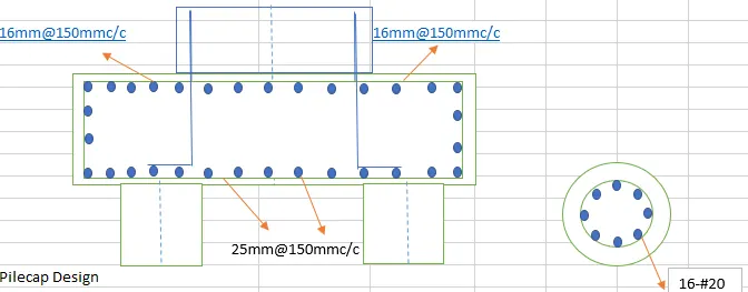
| Pilecap Design | ||||
| Critical section for BM is at the face of pire | ||||
| Total pile reaction on one side of critical section | ||||
| P1+P5 | 405.10 kN | |||
| P4+P8 | 287.15 kN | |||
| Max | 405.10 kN | |||
| Leverarm = 0.5*(10.800-1.772) | 4.514 | |||
| Maximum BM= 405.1*4.514= | 1828.52 kN | |||
| Eff.Depth req d = sqrt(M/(k*fck*b)) | ||||
| Xumax/d | 0.456 | K=0.134 | ||
| d req = sqrt(1.828.52*10^6/(0.1338*35*5100)) | 276.7329 mm | |||
| Dia of reinforcement | 25 mm | |||
| Eff. Depth available, d | 1500-75-25-12.5 | 1387.5mm> reqd. OK | ||
| Area of steel | ||||
| R= 1829*10^6/(5100*1387.5^2) | 0.186236 | |||
| Ast | 3049 mm^2 | |||
| Provide | 25mm dia @ 150 mm C/C in 1 layer | Ast provided 16689.7 mm^2, OK | ||