Week 11 Car Crash simulation
CAR CRASH SIMULATION
OBJECTIVE
To perform a explicit dynamic simulation of a car crash against a wall thereby determining the total deformation and Equivalent stresses acting on the model.
A total of 3 different cases - involving 3 different thickness values for the car component will be used and the effect of total deformation and stresses generated in the component will be studied.
PROCEDURE:
- Create a new explicit dynamic simulation
- Import Aluminium alloy NL, Titanium alloy NL, and Copper alloy NL materials from general nonlinear materials module as the desired material for the bucket components
- Import the geometry model from spaceclaim GUI
- Then the model module of explicit dynamics is again updated.
- Open the model in ansys mechanical module.
Material & thickness assignment
Assign Stainless steel NL for the BIW component
And the rigidwall can either be modeled as flexible or rigid. While a rigid stiffness behaviour is recommended, in this project the wall is assumed to be deformable (i.e stiffness = flexible)
Set the thickness of the BIW comp as 0.3mm for the first case and increment it by a value of 0.3mm in the following two cases.
NOTE: To accomplish the extraction of individual results in all 3 cases, set the thickness tab in geometry to Parameterized
Contacts
Delete unnecessary contacts since contact forces wont be studied
However, set a body interaction defined for all bodies for the dynamic analysis
Symmetry
Define the symmetrical edges of both the car body and wall from the model tab.
Mesh
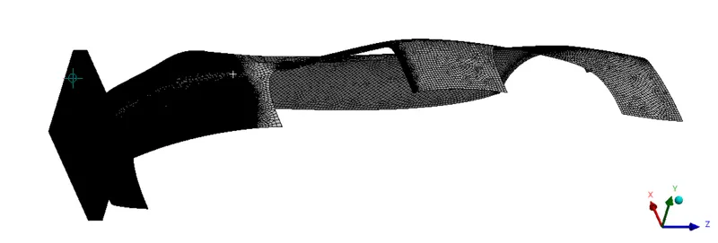
A coarse mesh with a sizing of 20mm is generated on the backend of the BIW component
while the frontend which would come in impact with the wall is refined for mesh parameters with a target length of 5mm. This is achieved by creating a sphere at the centre with a radius of 1000mm

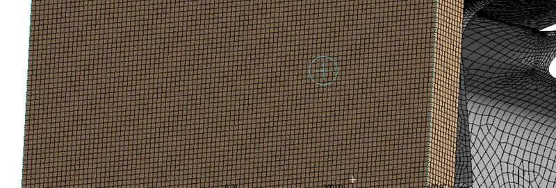
The wall is modeled with hexa elements (3D) since it isnt comprised of any complex features and hex provides a more accurate solution result.
Loading & Boundary conditions
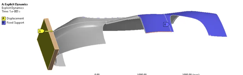
The end time is set as 0.001s
Increase the energy error to 5 because though the time duration is very less, the geomerty of the component is long enough that this energy error could be added at each node.
The backend of the car body is fixed since they are less likely to come in contact with the wall upon impact.
The wall is displaced to a distance of 500mm towards the car component.
RESULTS:
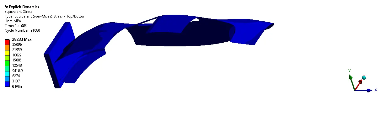
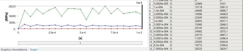
EQUIVALENT STRESS
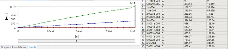
TOTAL DEFORMATION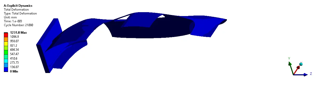
PARAMETRIC STUDY
A parameteric study was performed on the same model with varying thickness for the BIW component.
To accomplish this,
- Parametrize the required input and output parameters
- Input - thickness for BIW structure
- Output - min/max/avg of Total deformation and equivalent stress
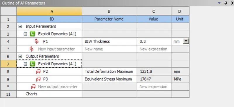
Then select - 'Update all design points'
This function would rerun the entire simulation using the new input criteria and calculate the specified output variables (as shown below)
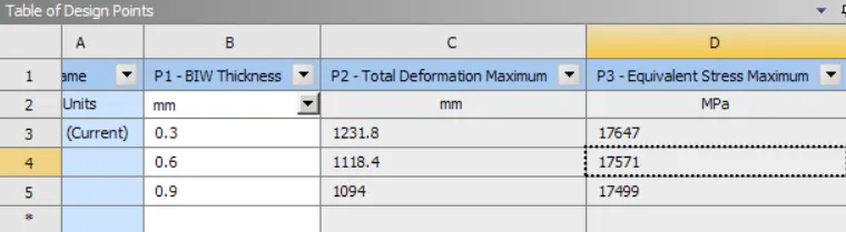
Then if required each result can be visualized individually by setting the required parametric study to current
CONCLUSION
Hence from the results extracted from the parametric study, we can conclude that as the thickness of the BIW component is increased the total deformation and the equivalent stress generated in the component diminishes by a small factor. This is becasue as the thickness is increase - more and more material is added to the structure, this increases the FOS of the entire system while also providing additional stiffness. While this seem ideal, this however adds up to production and material cost and must only be considered if and only if the structure fails i.e if the stress limit exceeds the ultimate tensile/compressive strength of that material in a particular area of the structure.