Week 11 Car Crash simulation
AIM: - PERFORM A PARAMETRIC STUDY OF CAR CRASH SIMULATION FOR THREE DIFFERENT VALUES OF THICKNESS FOR THE CAR BODY.
Objectives:
Perform the parametric study for three different thickness values of the car body.
Obtain the Total Deformation and Equivalent Stress for each case.
The Explicit Dynamics Analysis was taken from the Analysis Systems of the Ansys Workbench to perform the study.
Geometry was imported into the project environment, right-click on Model and select Edit to load the model in the Mechanical Module. The model looks like this in the module:
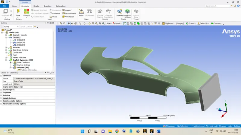
The parts were renamed accordingly and the unwanted parts were suppressed from the analysis.
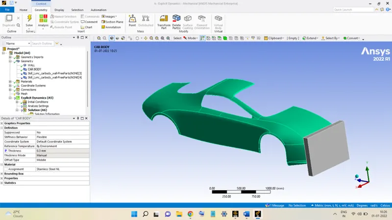
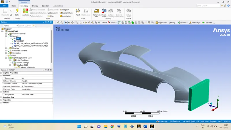
The CAR BODY was given an arbitrary Thickness of 0.3 mm and the Thickness of the CAR BODY was also selected as the Input Parameter for the parametric study.
The Symmetry Regions for both the WALL and CAR BODY were also added to the model, as shown below:
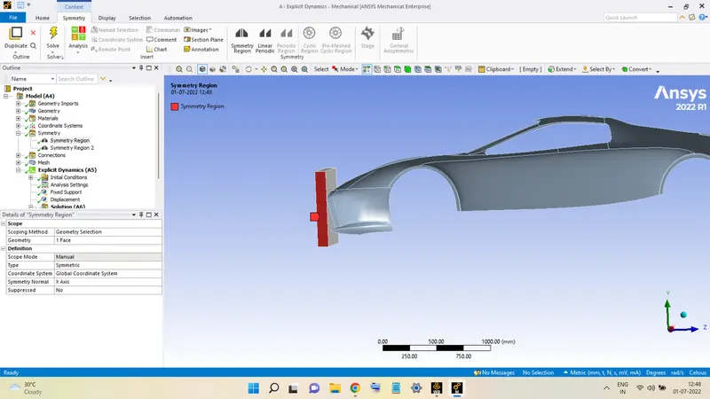
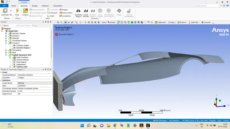
For the CAR BODY, the Edges were taken for the symmetry.
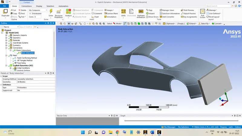
All the pre-defined Contact regions were deleted and the Body Interactions were kept Frictionless.
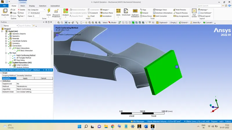
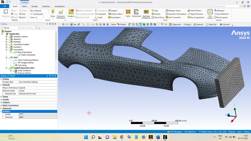
The WALL body was meshed using the Tetrahedrons Mesh Method.
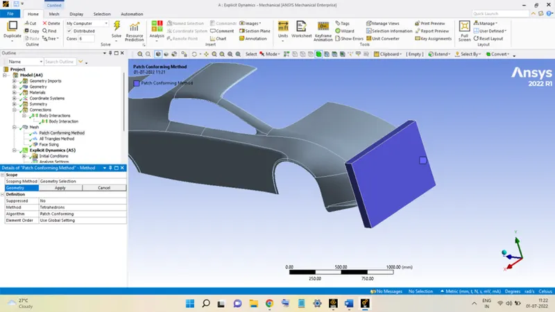
The CAR BODY is a surface body, so, is meshed using the Triangular Elements Method.
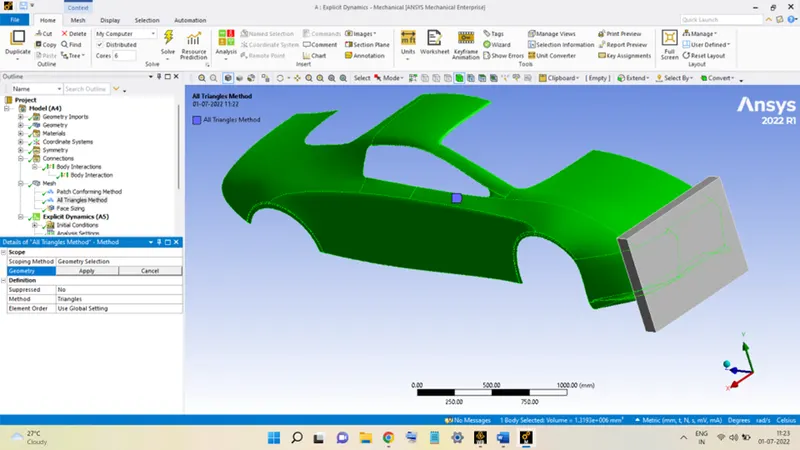
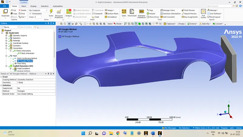
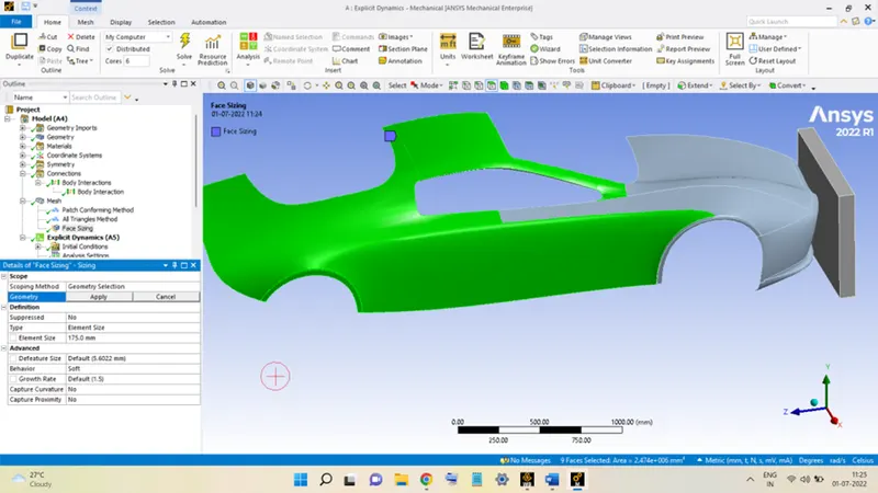
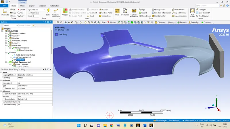
The rear surfaces of the CAR BODY meshed with large elements having an Element Size of 175 mm.
The model after successful meshing looks like this:
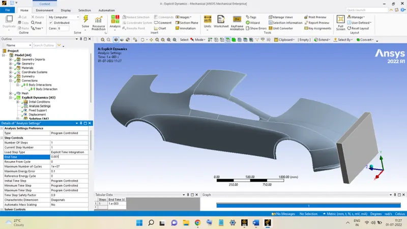
In Analysis Settings, the End Time was taken as 0.001 sec.
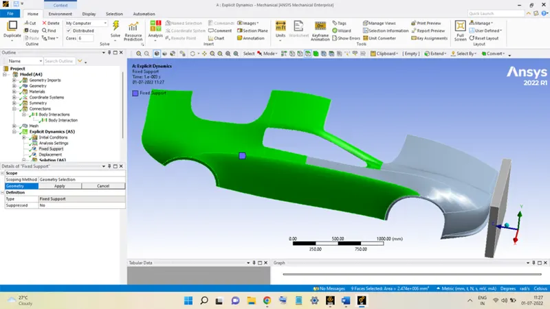
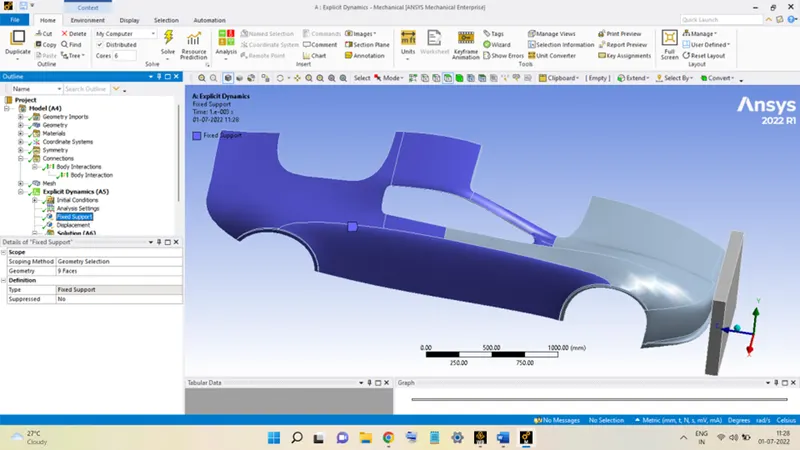
The rear faces of the CAR BODY were fixed for the analysis.
The WALL was given the Displacement Load of 500 mm along the positive Z-Axis.
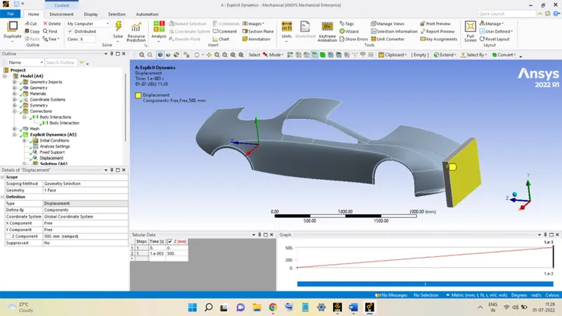
The model is now set up for analysis. The output results from the analysis are Directional Deformation of the CAR BODY along the Z-Axis, and Equivalent Stress developed in the CAR BODY during the analysis.
The maximum values of both the output results are taken as the Output Parameters of the Parametric analysis.
The analysis is then carried out for three thickness values taken:
a) 0.3 mm
b) 0.5 mm
c) 0.7 mm
The results for each case are as follows:
RESULTS
CASE 1: THICKNESS IS 0.3 mm
Stress:
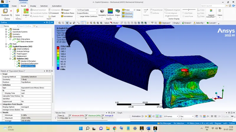
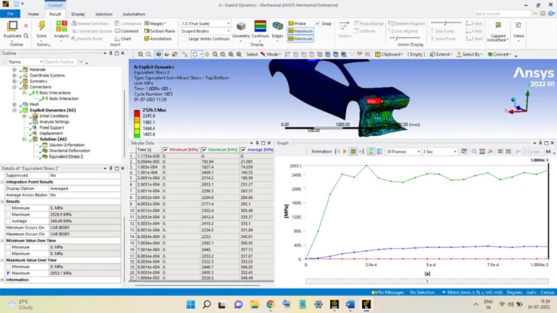
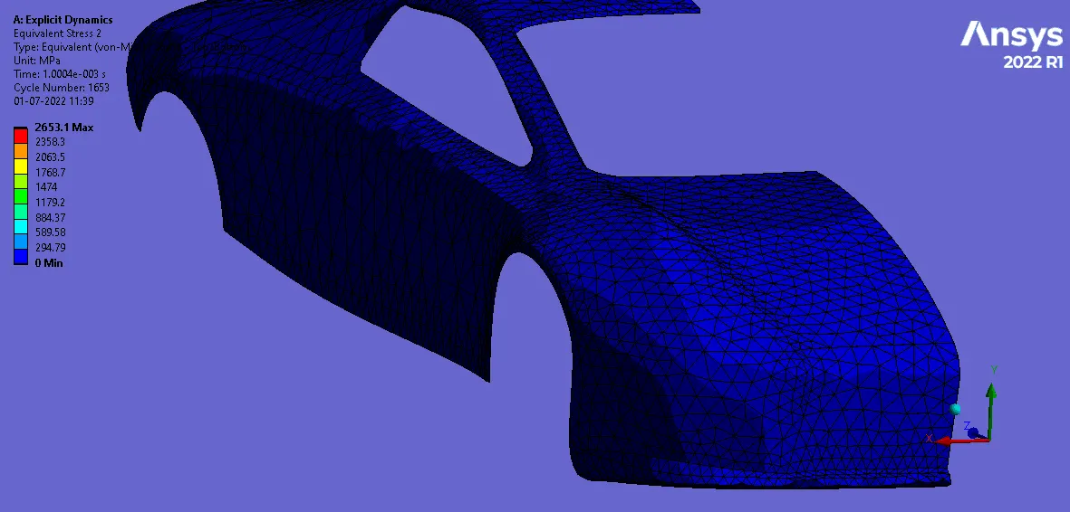
The stress developed in the CAR BODY is shown above, the maximum value of the stress is equal to 2653.1 MPa.
Deformation along Z-Axis
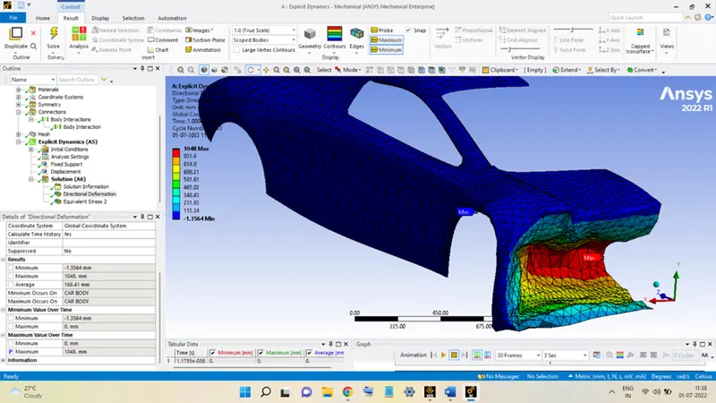
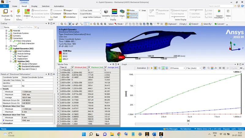
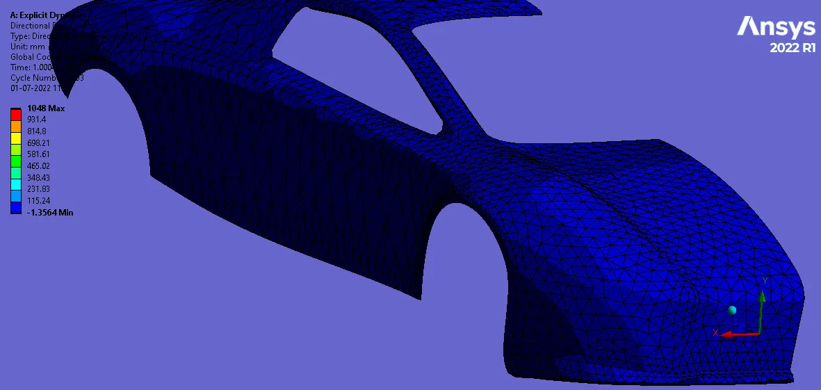
The deformation in the CAR BODY is shown above, the maximum value of the stress is 1048 mm.
CASE 2: THICKNESS IS 0.5 mm
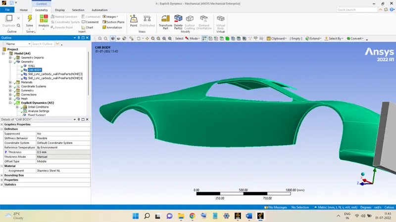
Stress:
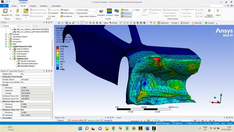
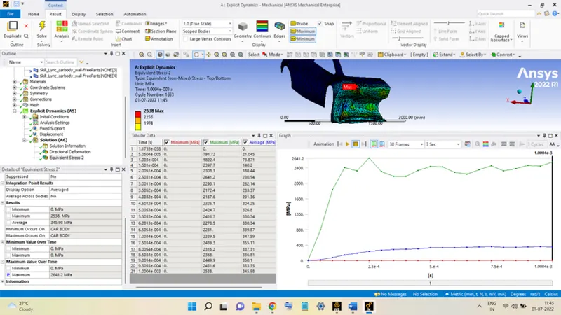
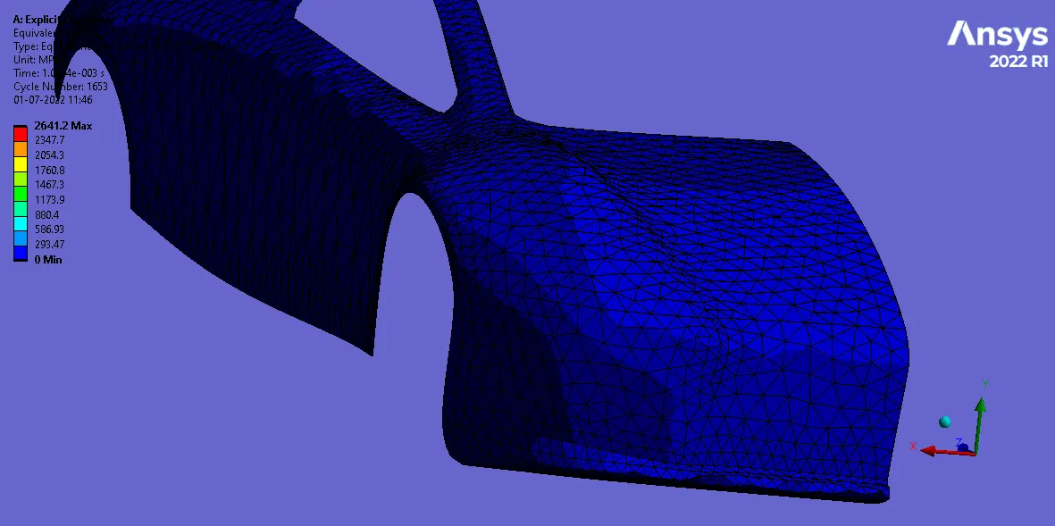
The stress developed in the CAR BODY is shown above, the maximum value of the stress is equal to 2641.2 MPa.
Deformation along Z-Axis
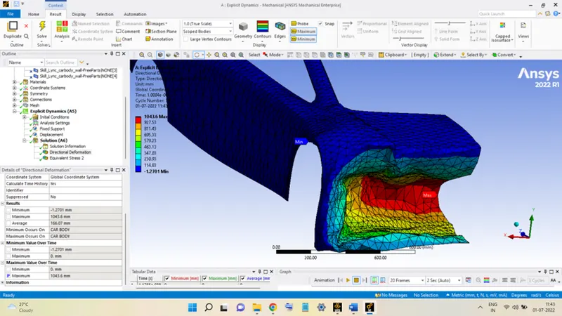
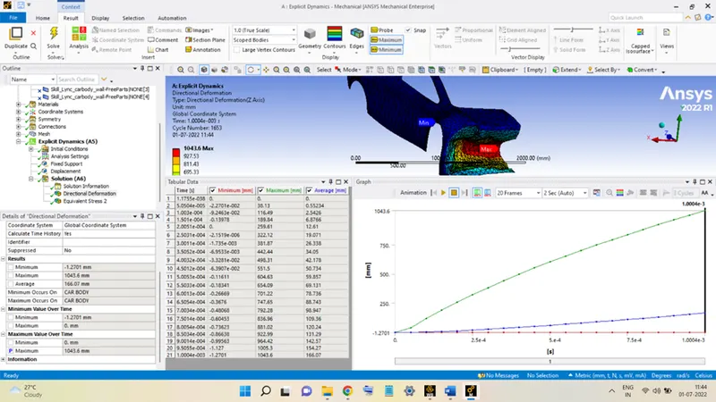
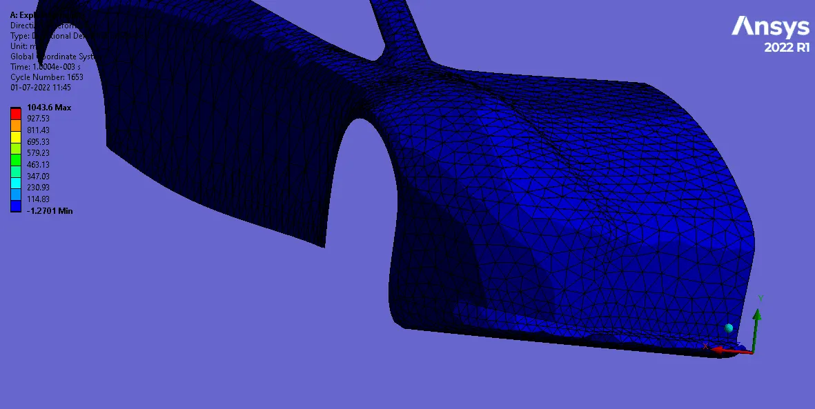
The deformation in the CAR BODY is shown above, the maximum value of the stress is 1043.6 mm.
CASE 3: THICKNESS IS 0.7 mm
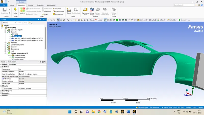
Stress:
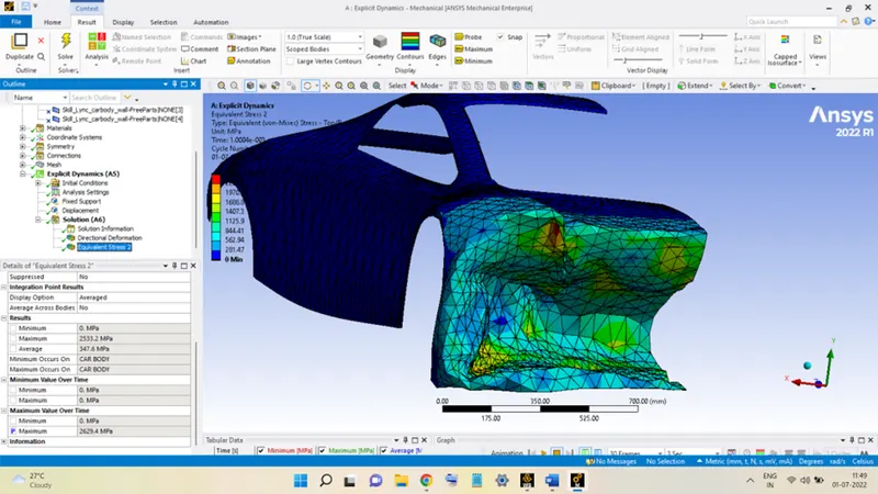
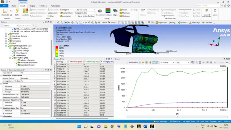
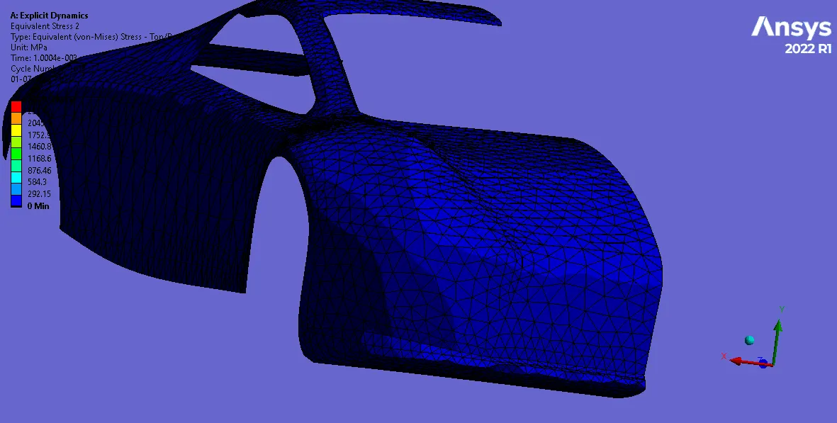
The stress developed in the CAR BODY is shown above, the maximum value of the stress is equal to 2641.2 MPa.
Deformation along Z-Axis
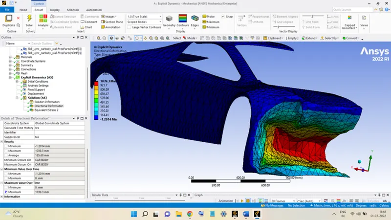
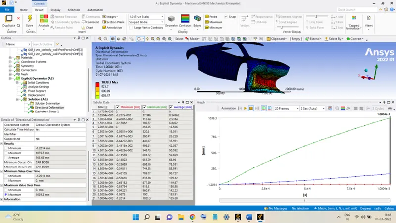
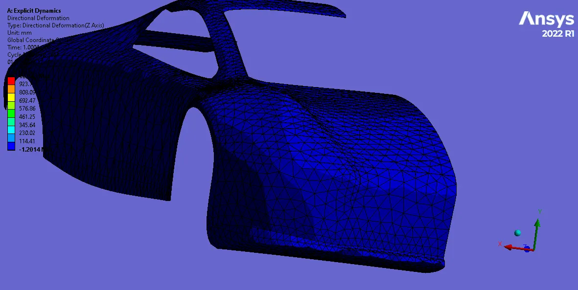
The deformation in the CAR BODY is shown above, the maximum value of the stress is 1039.3 mm.
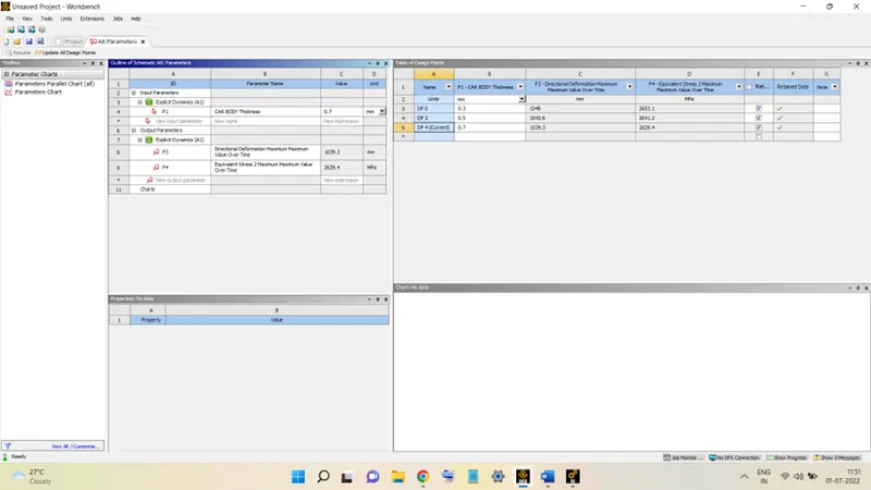
The parametric analysis results are shown in the figure below:
Comparison:
|
|
MAX. STRESS (MPa) |
MAX. DEFORMATION (mm) |
|
THICKNESS = 0.3 mm |
1048 |
2653.1 |
|
THICKNESS = 0.5 mm |
1043.6 |
2641.2 |
|
THICKNESS = 0.7 mm |
1039.3 |
2629.4 |
In the above table are the results from the parametric study, from this table it can be said that:
The maximum stress developed in CAR BODY is inversely proportional to the Thickness values and the same is true for the Deformation in the CAR BODY.
Hence, it is necessary to have an optimum thickness value for the CAR BODY.