Simulating Combustion of Natural Gas.
Objective:
Part I
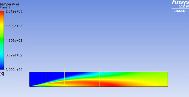
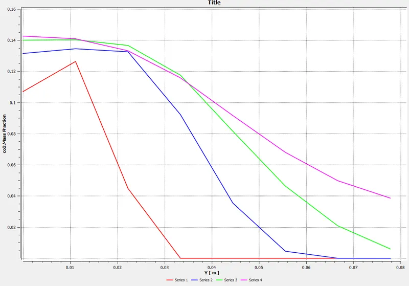
Perform a combustion simulation on the combustor model and plot the variation of the mass fraction of the different species in the simulation using line probes at different locations of the combustor as shown in Fig. You need to plot for CO2, H2O, CH4, N2, O2, NOx emissions & Soot formation.
Part II
As you must have observed from the above simulation, the Nox and soot are getting formed at the outlet of the combustor. Such formation has harmful effects on the environment and humans. The stringent government norms also demand the least formation of Nox and soot and to satisfy those requirements, you need to check the effect of adding the water in the fuel.
In this part, you need to add the water content in the fuel from 5% to 30% by mole and observe the effect of it on the results. It is necessary to provide line plots and contours to prove your claim.
You can use the parametric study approach if required.
Note:-
1. Use methane-air-2step as a mixture material than methane-air. [It allows to add water in the fuel or air]
2. Use a one-step soot model to calculate the soot formation.
Solution:
What is combustion modeling? How Turbulent combustion modeling is experimented & developed?
Combustion models for CFD refer to combustion models for computational fluid dynamics. Combustion is defined as a chemical reaction in which a hydrocarbon fuel reacts with an oxidant to form products, accompanied by the release of energy in the form of heat. Being an integral part of various engineering applications like Internal combustion engines, aircraft engines, rocket engines, furnace, and power station combustors combustion manifests itself as a wide domain during the design, analysis, and performance characteristics stages of the above-mentioned applications. With the added complexity of chemical kinetics and achieving reacting flow mixture environment, proper modeling physics has to be incorporated during Computational fluid dynamics(CFD). simulations of combustion. Hence the following discussion presents a general outline of the various adequate models incorporated with the Computational fluid dynamic code to model the process of combustion.
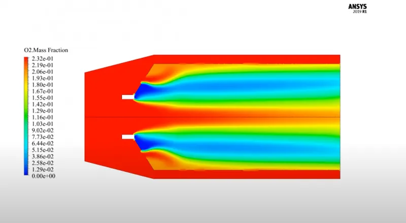
In simulations, the shift to LES allows a better representation of the turbulent flow in complex geometries, but despite the fact that the grid size is smaller than in RANS, the push towards realistic conditions and the need to include more detailed chemistry that includes very fast species and thin reaction zones emphasize the necessity of a sub-grid turbulent combustion model. Some paper discusses examples from current research with experiments and modeling that focus on flame transients (self-excited oscillations, local extinction), sprays, soot emissions, and practical applications. These demonstrate how current models are being validated by experimental data and the concerted efforts the community is taking to promote the modeling tools to industry.
In addition, the various coordinated International Workshops on non-premixed, premixed, and spray flames, and on soot are discussed and some of their target flames are explored. These comprise flames that are relatively simple to describe from a fluid mechanics perspective but contain difficult-to-model combustion problems such as extinction, pollutants, and multi-mode reaction zones. Recently, swirl spray flames, which are more representative of industrial devices, have been added to the target flames. Typically, good agreement is found with LES and some combustion models such as the progress variable - mixture fraction flamelet model, the Conditional Moment Closure, and the Transported PDF method, but predicting soot emissions and the condition of complete extinction in complex geometries is still elusive.
As we discussed the theory behind turbulence combustion modeling in the above section, we are about to begin the simulation part. We are going to export the geometry in SpaceClaim.
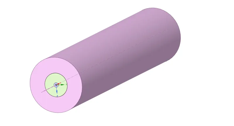
Now the geometry is a complete solid cylinder and we need a slice or frame of the element of the particular setup. And therefore we are going to use a few tools to get the slice of the geometry and build the setup.
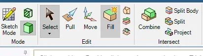
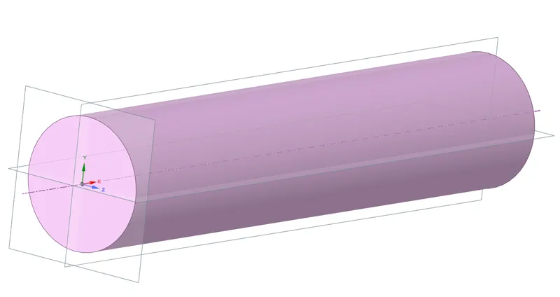
we make 3 planes and cut them appropriately to get the 1/4th of the part and then we are going to copy the slide into another.
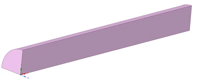
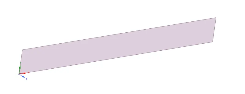
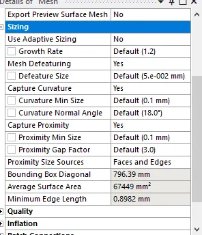
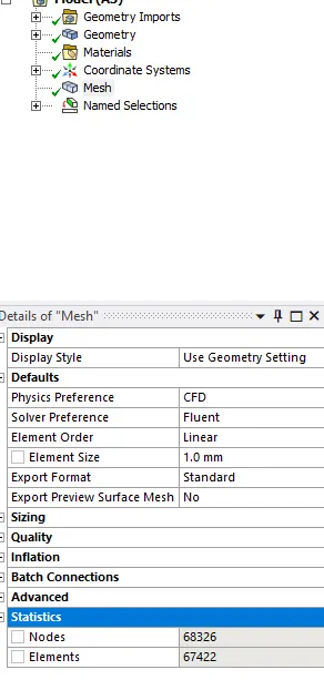
Now that we got the slicing part we are going to mesh the element.

Now we are going to move on to Setting up the case for combustion simulation in Fluent.
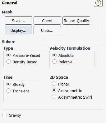
here we have chosen AXISYMMETRIC as the SLICE we have is at the axis and is symmetric throughout X-axis. So if we rotate the slice about the X-axis we get the whole cylinder. Like what we actually did in SpaceClaim.
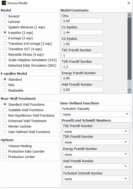
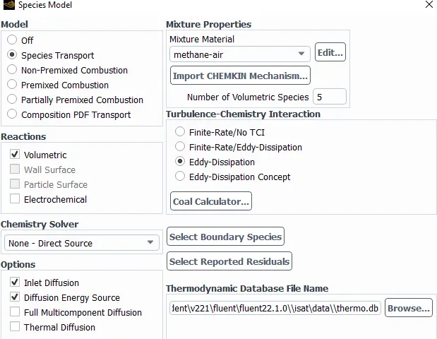
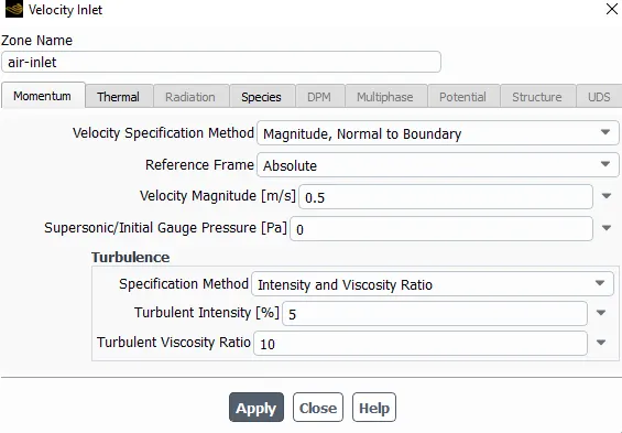
Setting up the Boundary conditions.
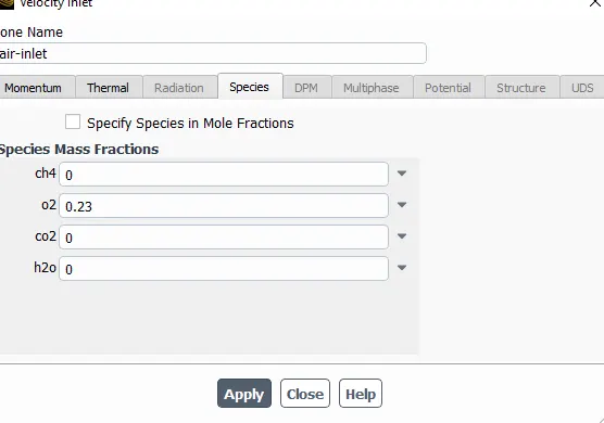
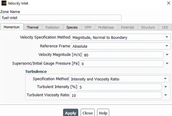
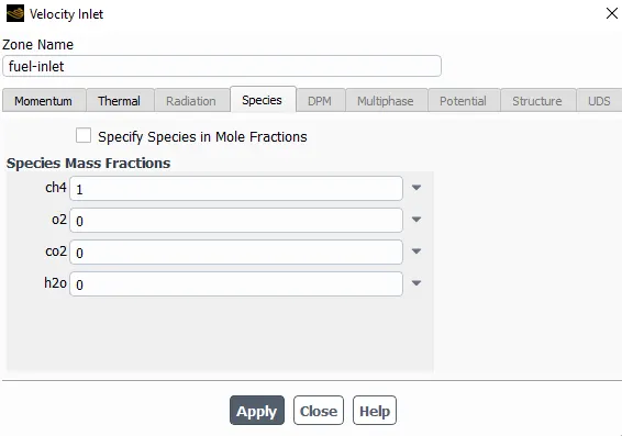
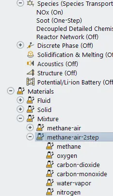
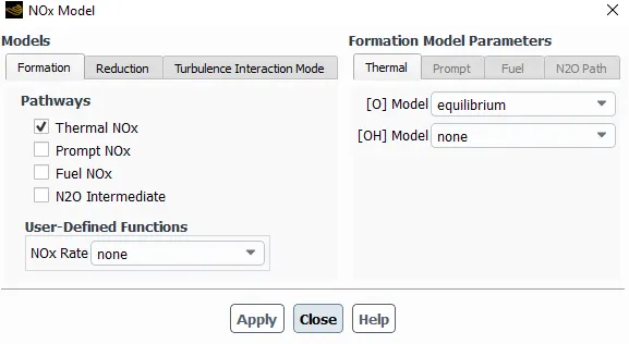
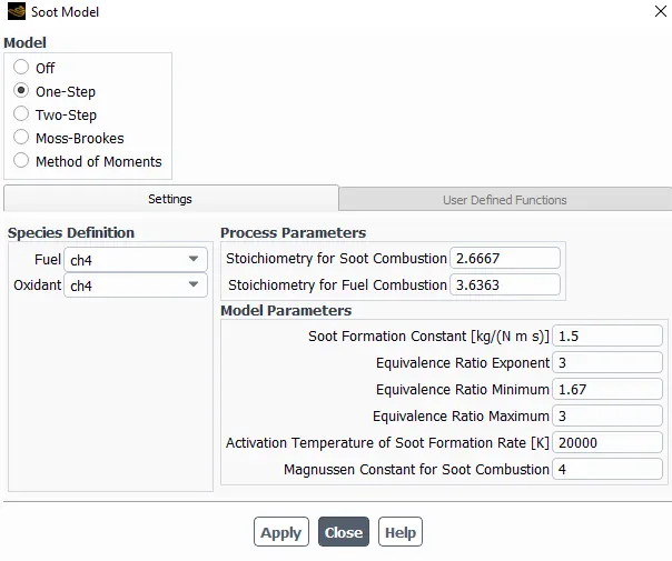

After this, we run for 300-500 iterations and nearly around 176th we are at convergence.
OUTPUT:
Part I
Performing a combustion simulation on the combustor model and plot the variation of the mass fraction of the different species in the simulation using line probes at different locations of the combustor as shown in Fig. You need to plot for CO2, H2O, CH4, N2, O2, NOx emissions & Soot formation.
Now as for this part we are going to open the setup in CFD-POST where we analyze the results using line probes and plot different species at different location lines.
Contours:
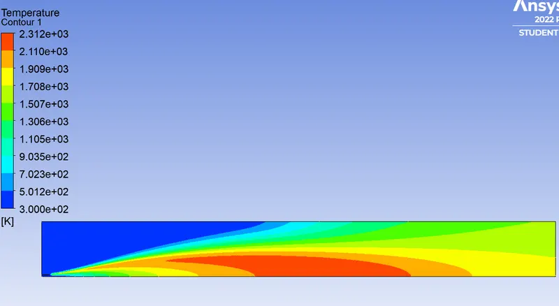
Temp:
CH4:
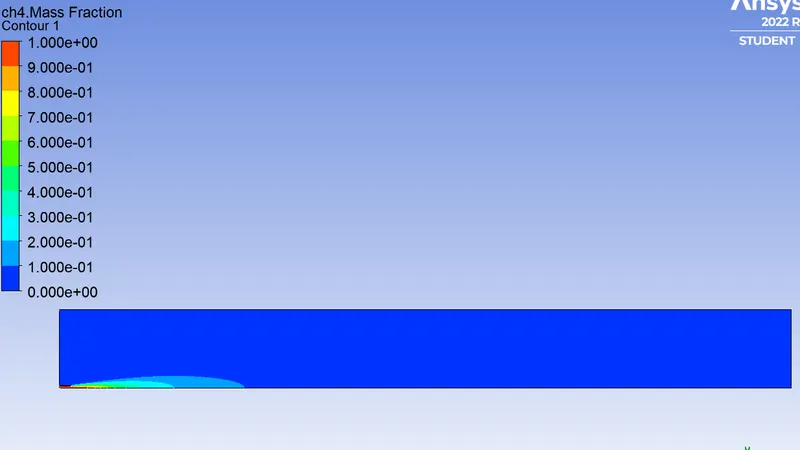
CO2:
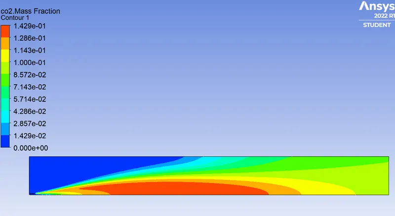
H2O:
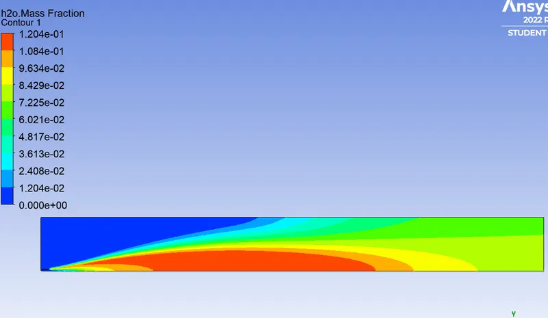
CO2:
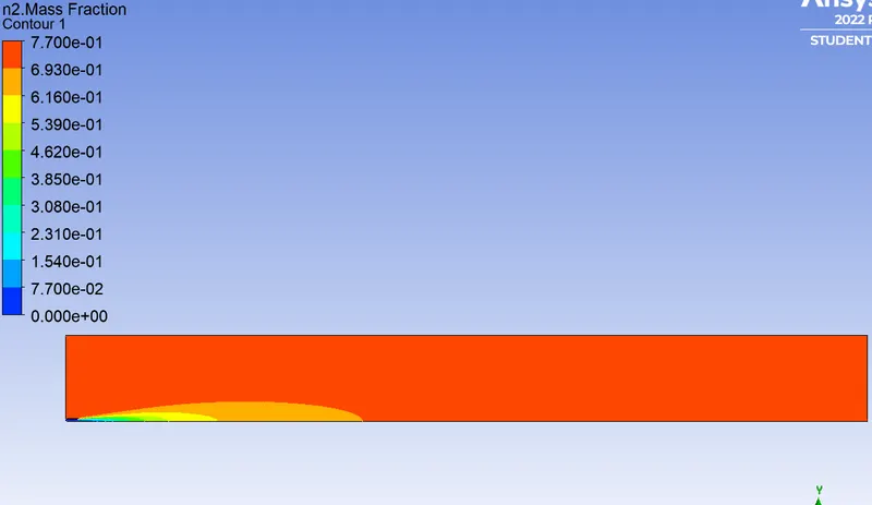
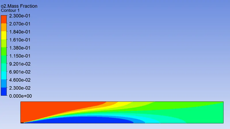
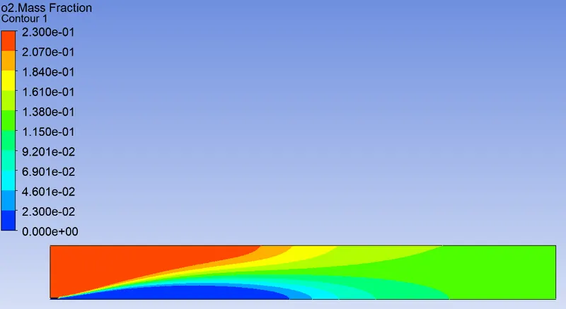
O2:
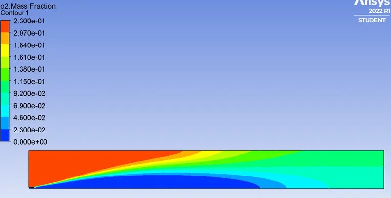
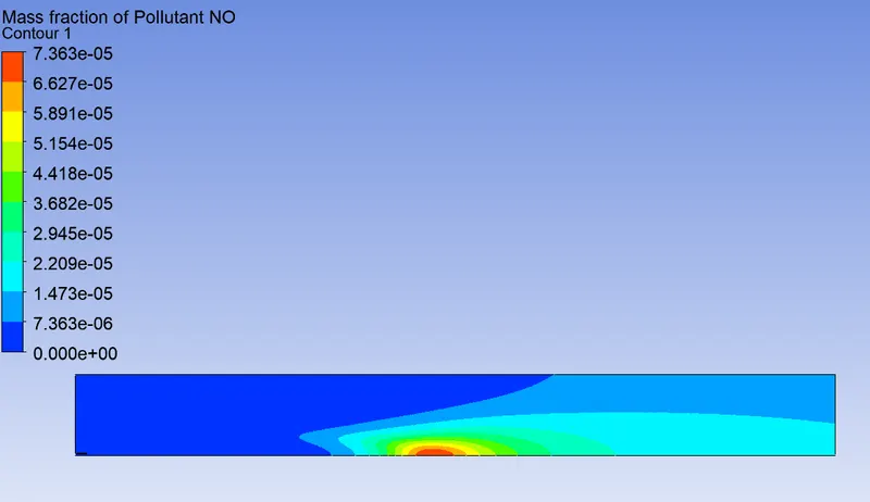
NOx:
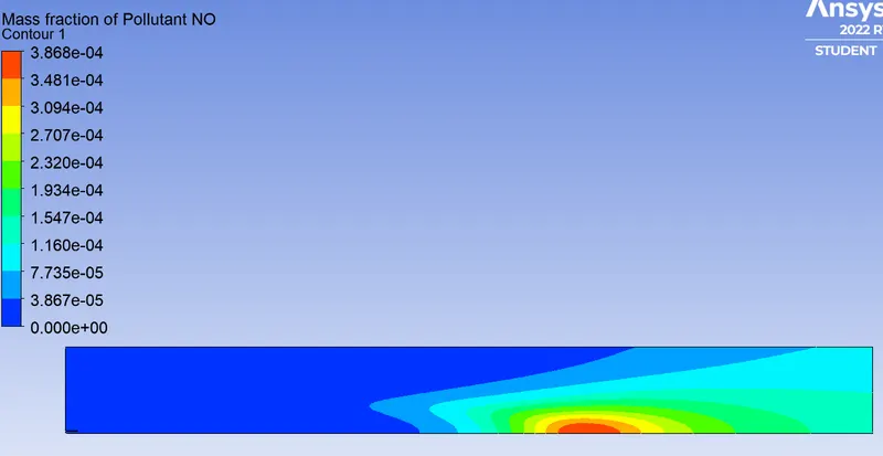
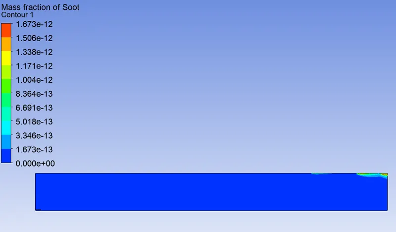
Soot:
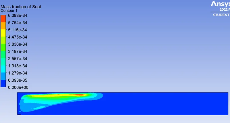
CO2:
H2O:
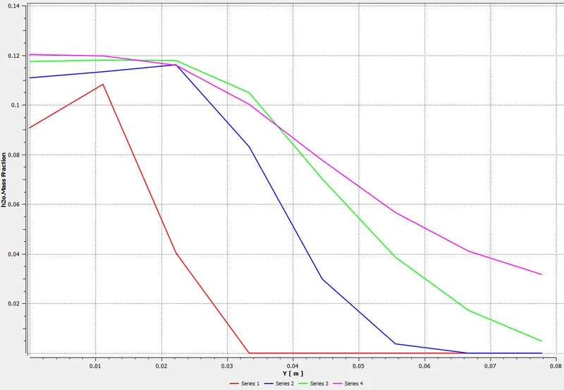
CH4:
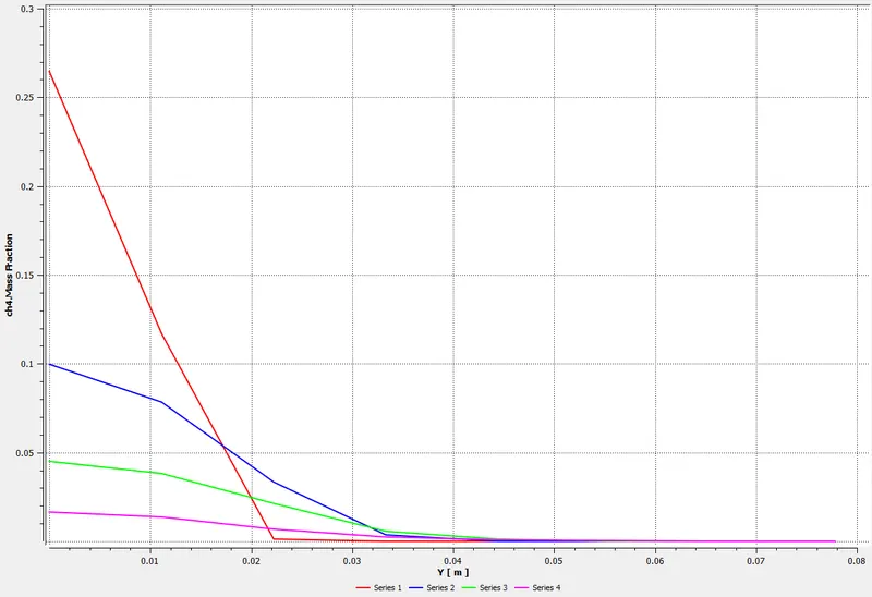
N2:
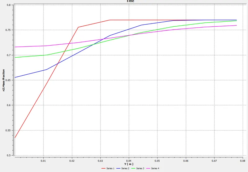
O2:
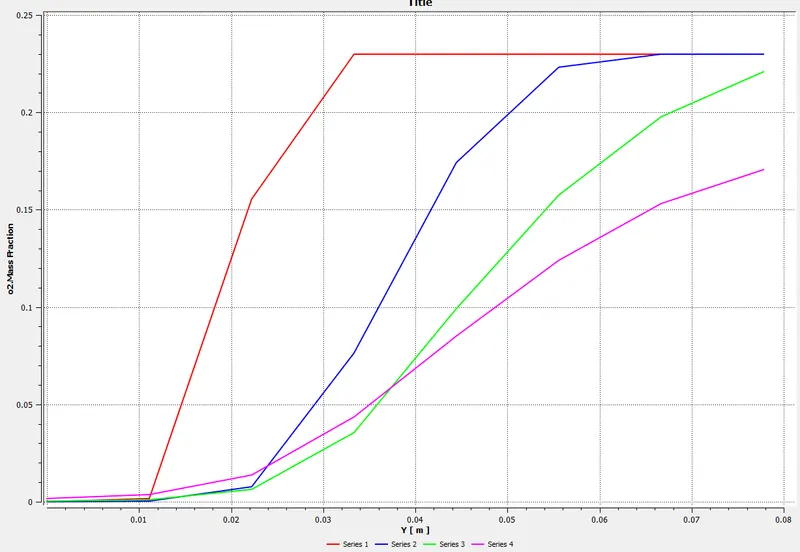
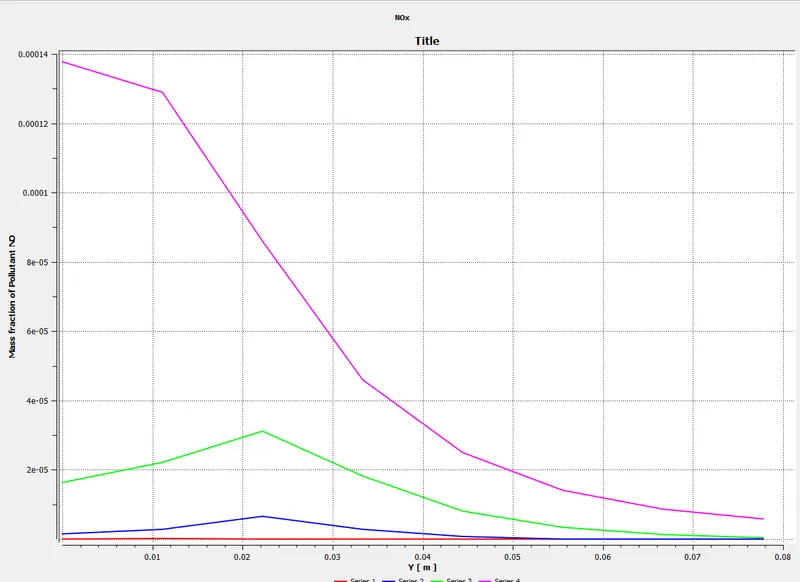
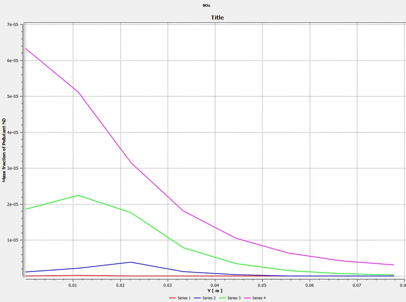
NOx:
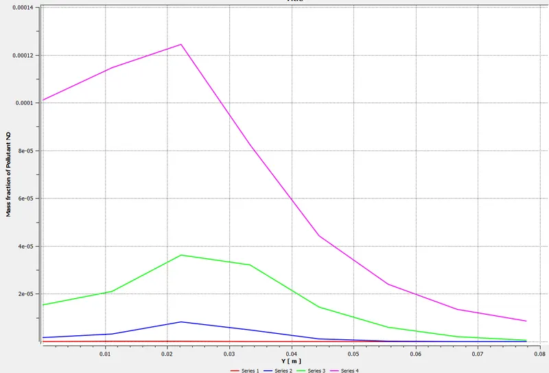
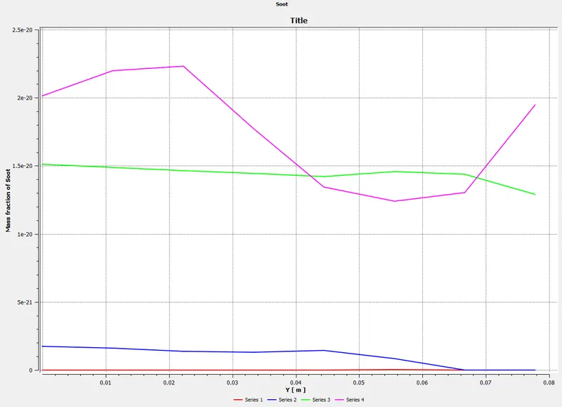
Soot:
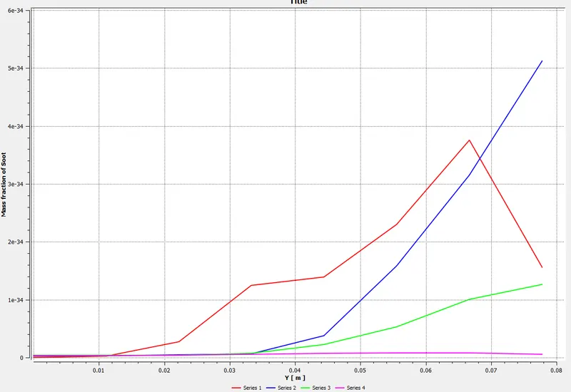
Part II
As you must have observed from the above simulation, the Nox and soot are getting formed at the outlet of the combustor. Such formation has harmful effects on the environment and humans. The stringent government norms also demand the least formation of Nox and soot and to satisfy those requirements, you need to check the effect of adding the water in the fuel.
In this part, we need to add the water content in the fuel from 5% to 30% by mole and observe the effect of it on the results. It is necessary to provide line plots and contours to prove your claim.
Here we have used the parametric tool to run 3 different cases at once:
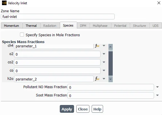
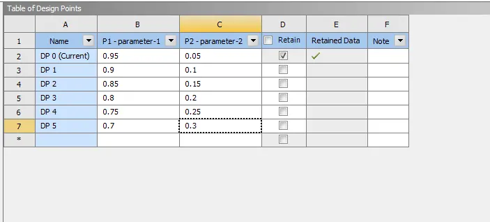
It shows here that we have 7 parameters but initially, it's just a trial case so originally we ran 3 parametric studies as below:
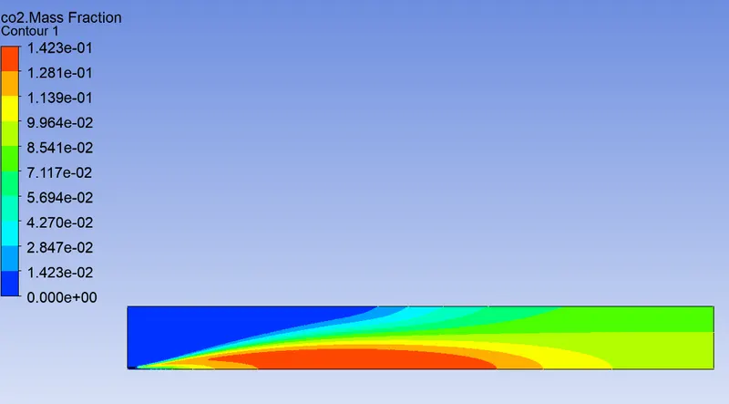
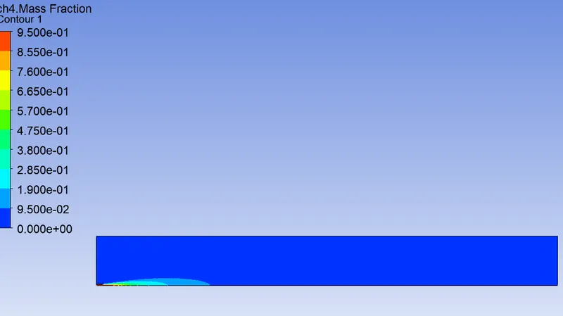
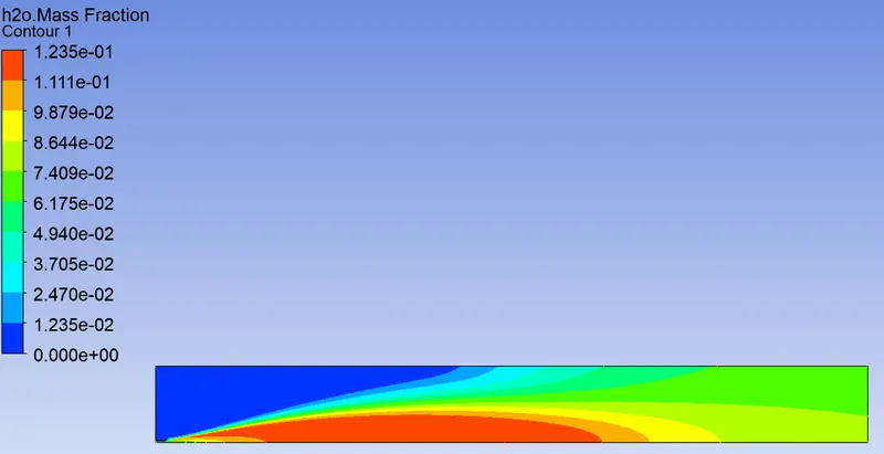
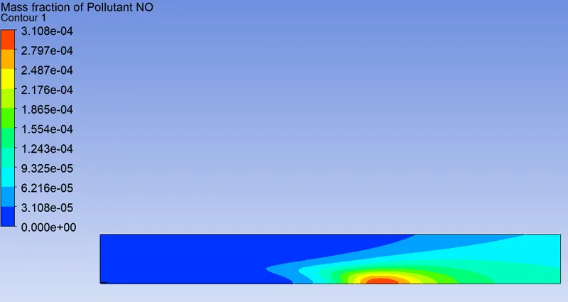
Water content at 5%:
CO2:
CH4:
H20:
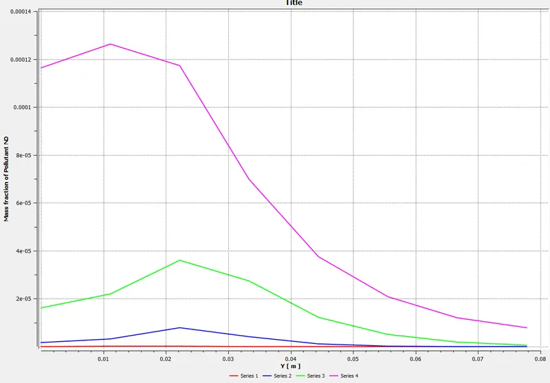
NOx:
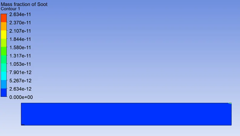
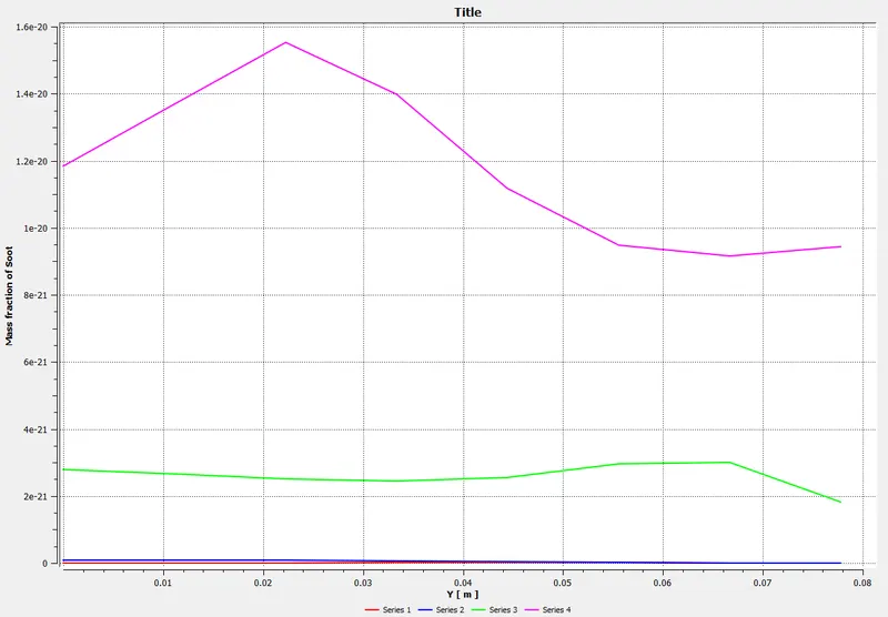
Soot:
NOx plot:
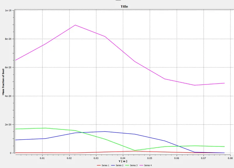
Soot Plot:
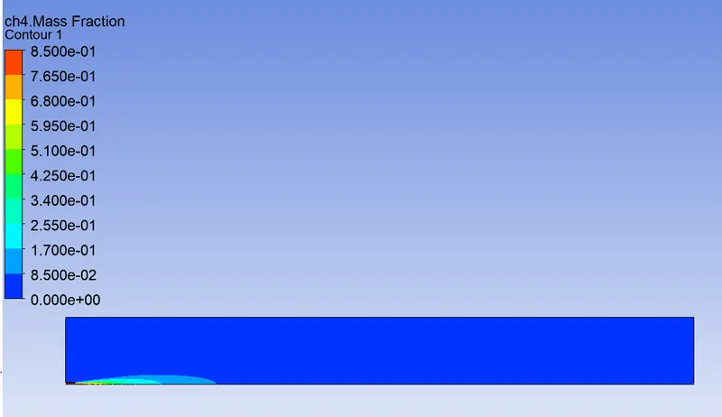
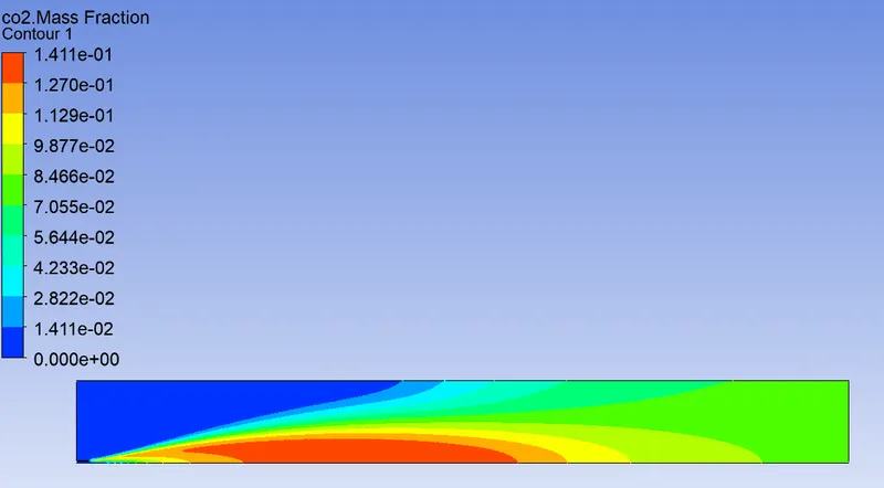
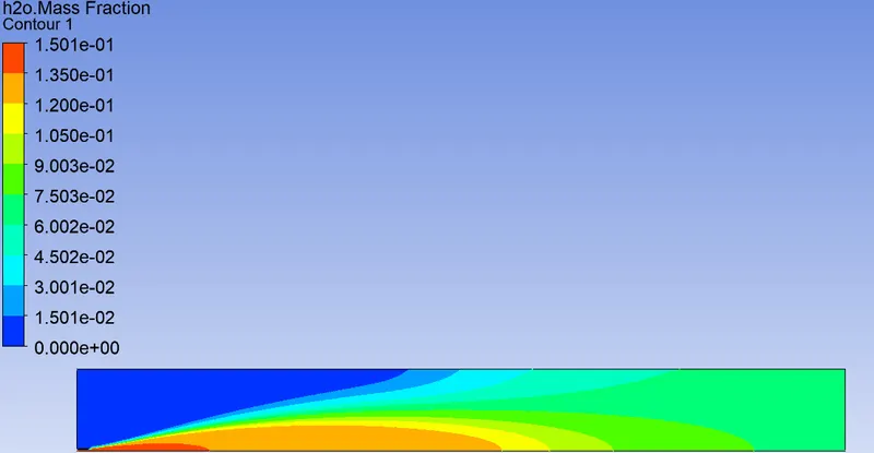
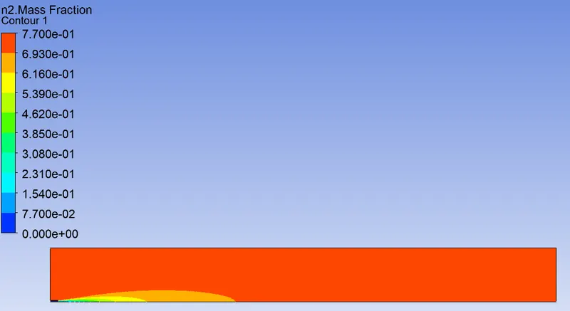
Water content at 15%:
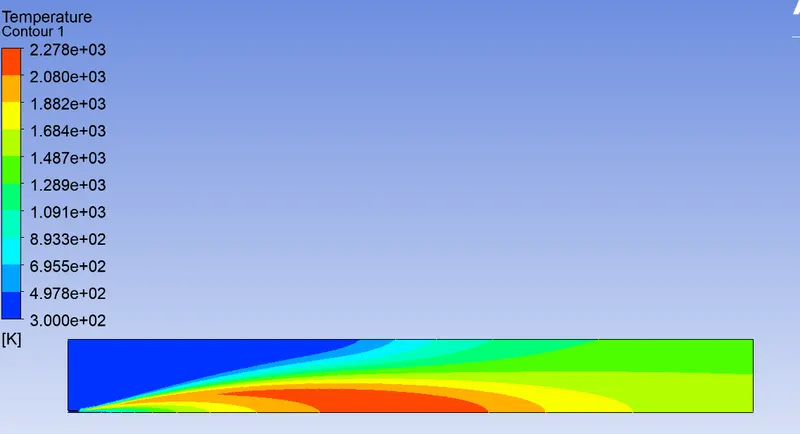
Water content at 30%:
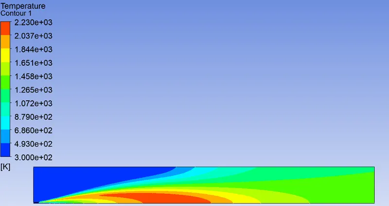
TEMP:
CH4:
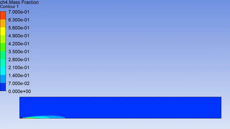
CO2:
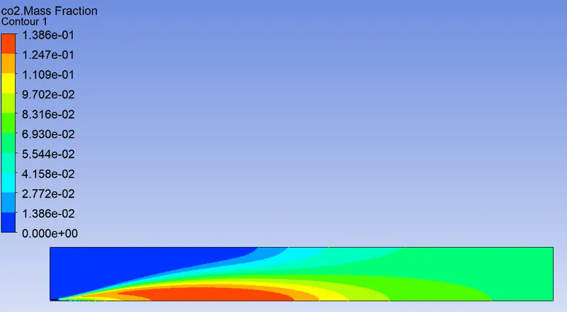
H2O:
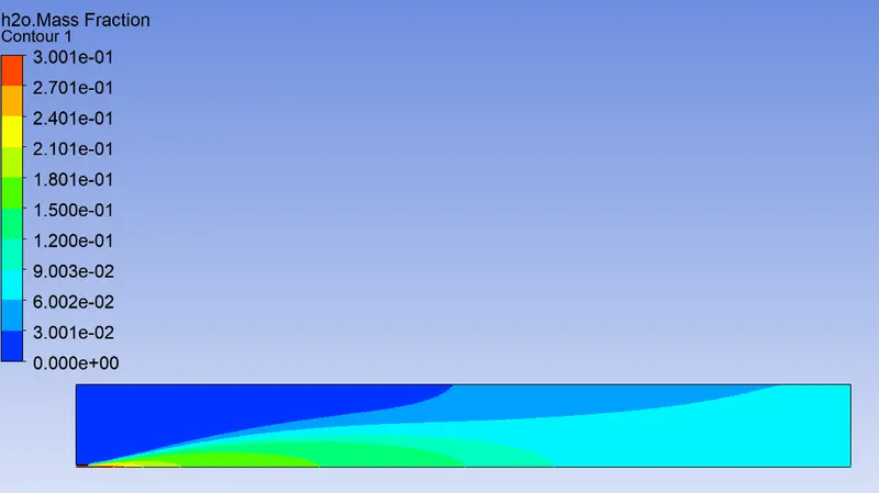
N2:
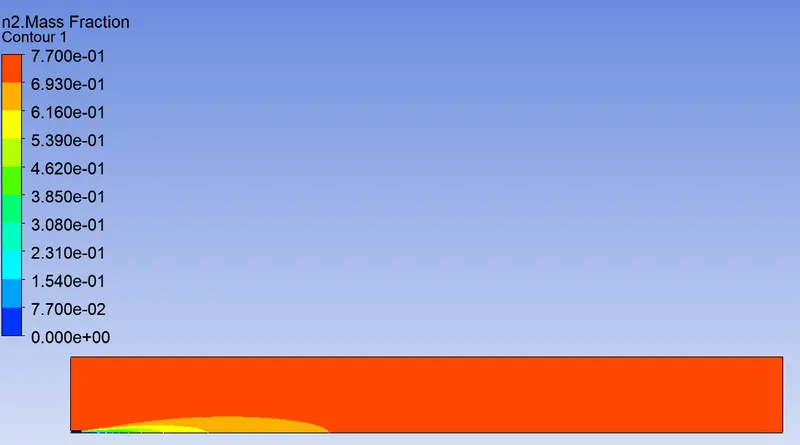
O2:
Nox:
Soot:
Nox Plot:
Soot Plot:
References:
Turbulent Combustion Modelling and Experiments: Recent Trends and Developments | SpringerLink
Combustion models for CFD - Wikipedia
Non-Premixed Combustion, ANSYS Fluent CFD Simulation Training - MR CFD (mr-cfd.com)