Project 1 - FULL HYDRO case set up (PFI)
Project-1 Surface Preparation and Boundary Flagging [Full Hydro case setup-(PFI)]
Aim: To perform Surface Preparation and Boundary Flagging on the IC engine and setting up Full Hydro case setup-(PFI)simulation.
Objective:
- To perform surface preparation and flag the boundaries on a given IC engine case.
- Setting up Full Hydro case setup-(PFI)simulation for the setup.
- To show the animation how all the valves and pistons move according to crank angles.
- To Calculate the combustion efficiency of this engine.
- Using the engine performance calculator, determining the power and torque for this engine.
Given inputs:
Engine Geometric Parameters
- Bore =0.086 m
- Stroke = 0.09 m
- Connecting rod length = 0.18 m
- RPM = 3000
Run Parameters
- Simulation mode: No Hydro
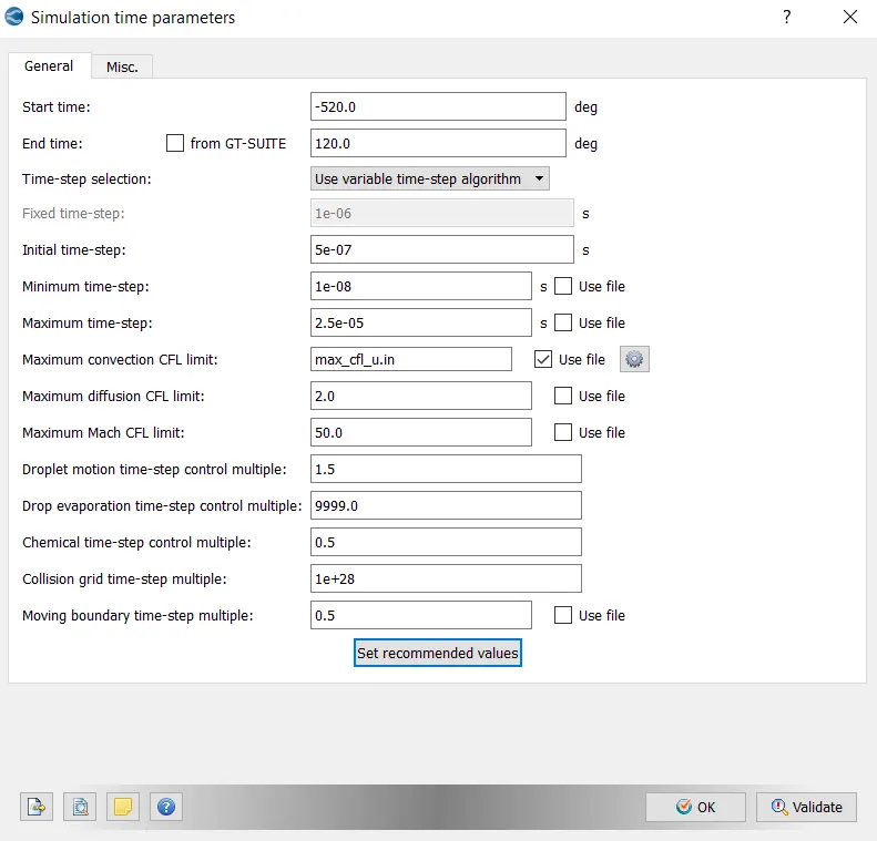
Simulation time parameters
- Start time : -520 deg
- end time : 120 deg
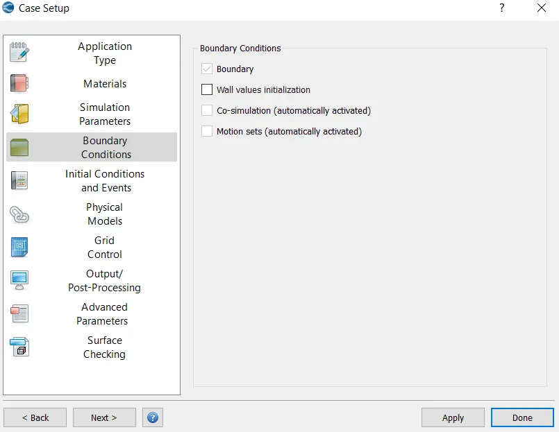
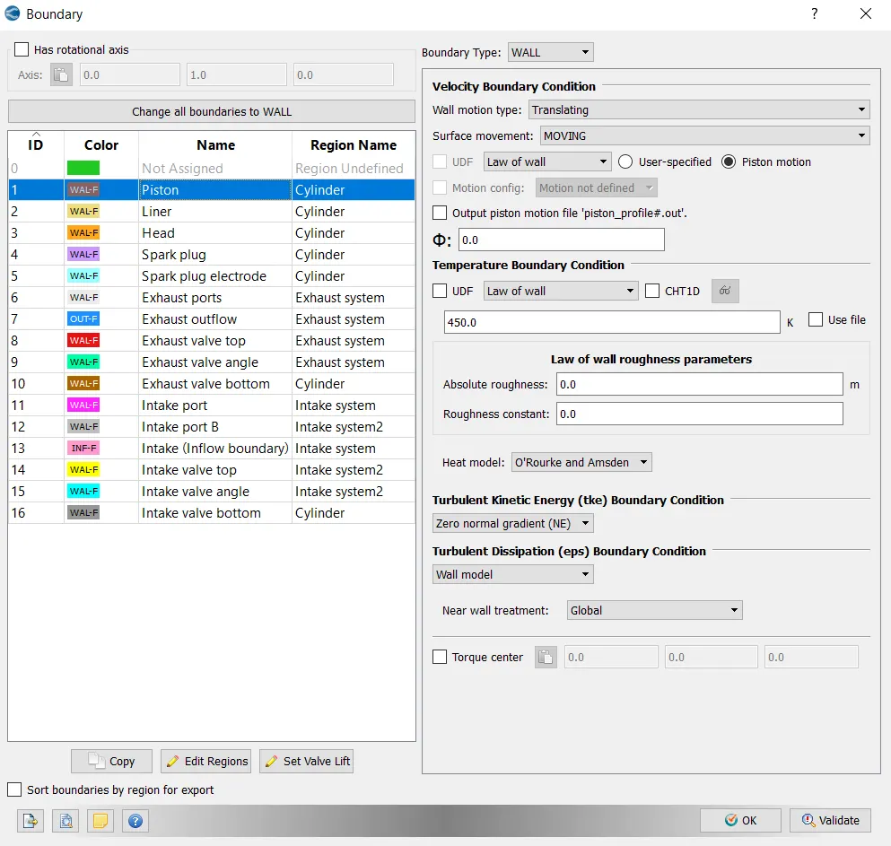
Boundary conditions
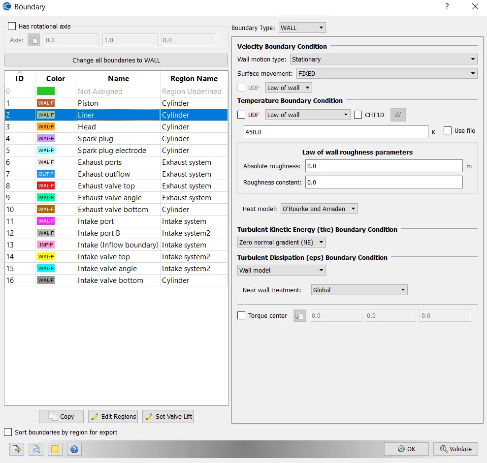
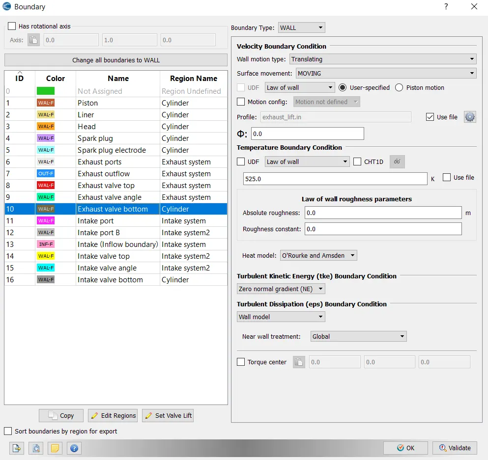
- Piston temperature - 450K
- Liner temperature - 450K
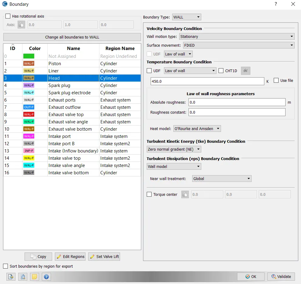
- Head temperature - 450K
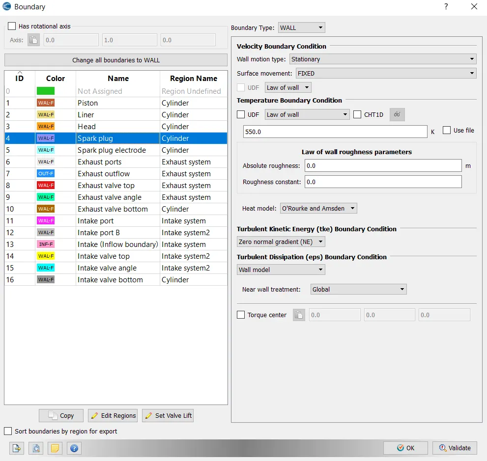
- Spark Plug temperature - 550K
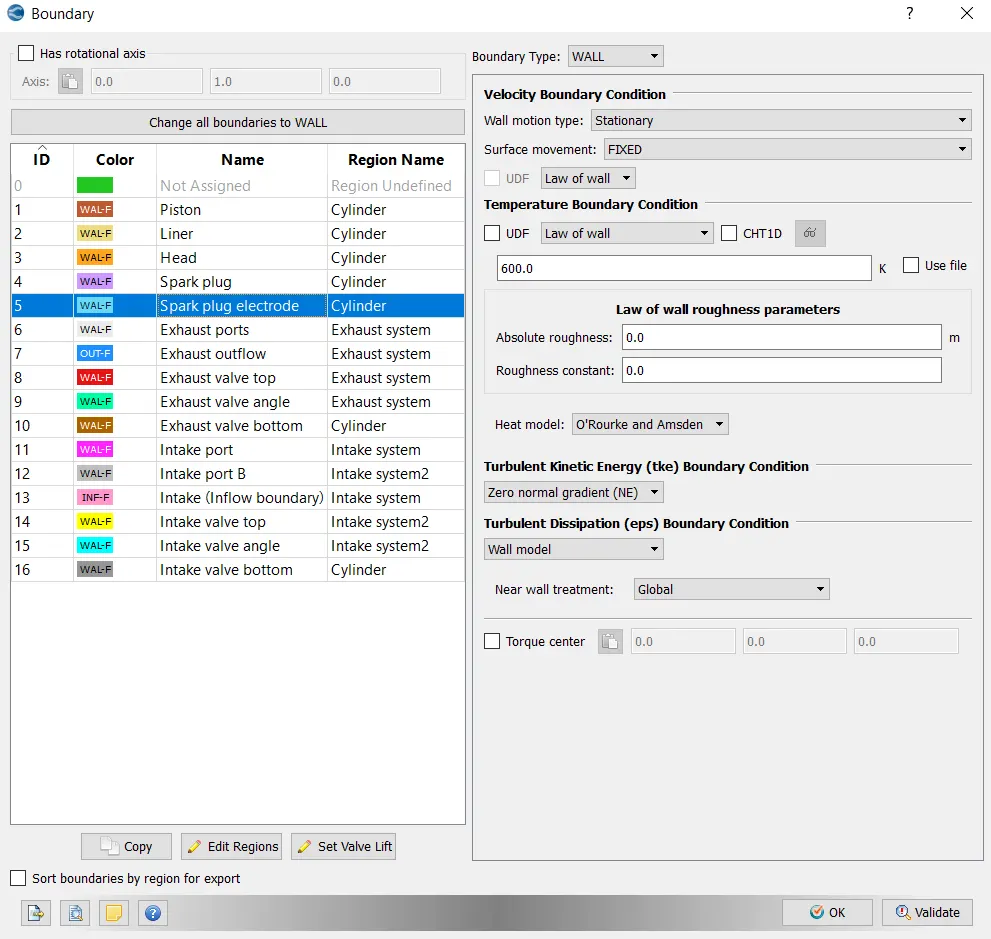
- Spark Plug electrode temperature - 600K
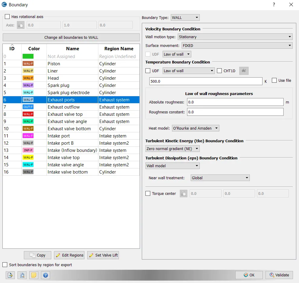
- Exhaust ports temperature - 500K
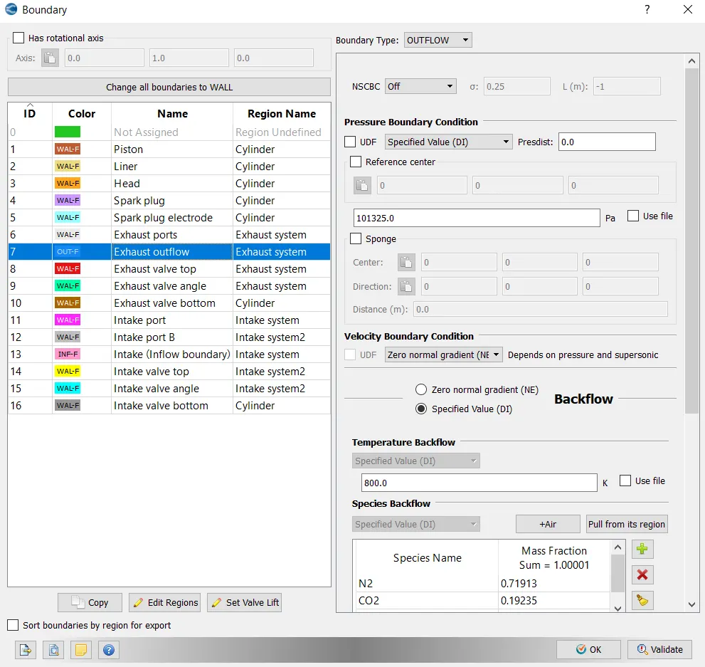
- Exhaut outflow - 1 bar
- Exhaust outlflow temperature - 800k
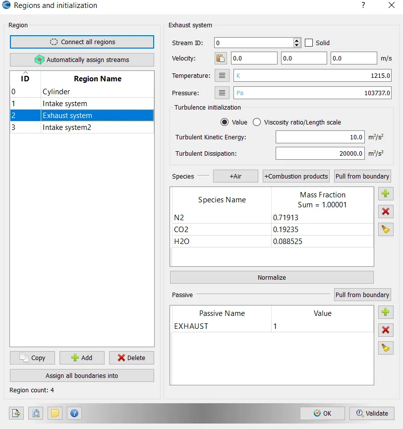
- Exhaust species concentration - Calculate the stoichiometric condition
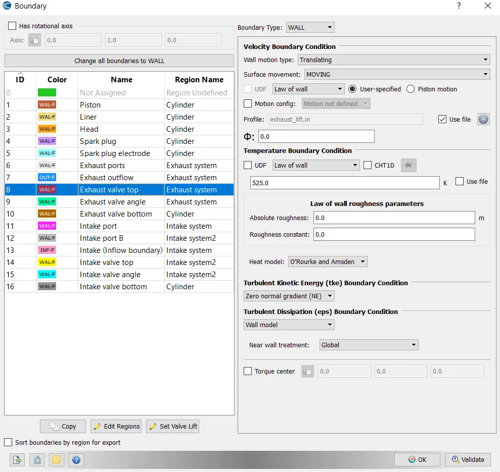
- Exhaust valve top temperature - 525K
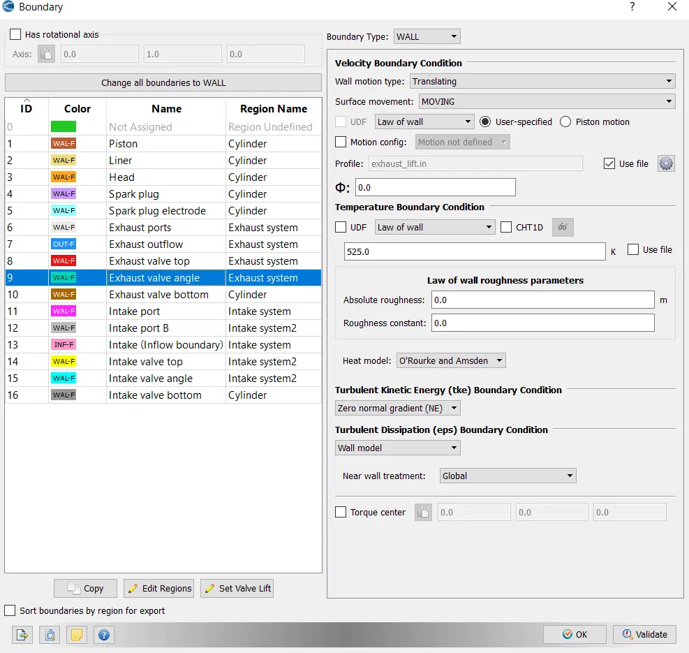
- Exhaust valve angle temperature - 525K
- Exhaust valve bottom temeprature - 525K
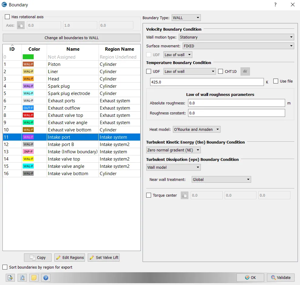
- Intake port - 1 temperature 425K
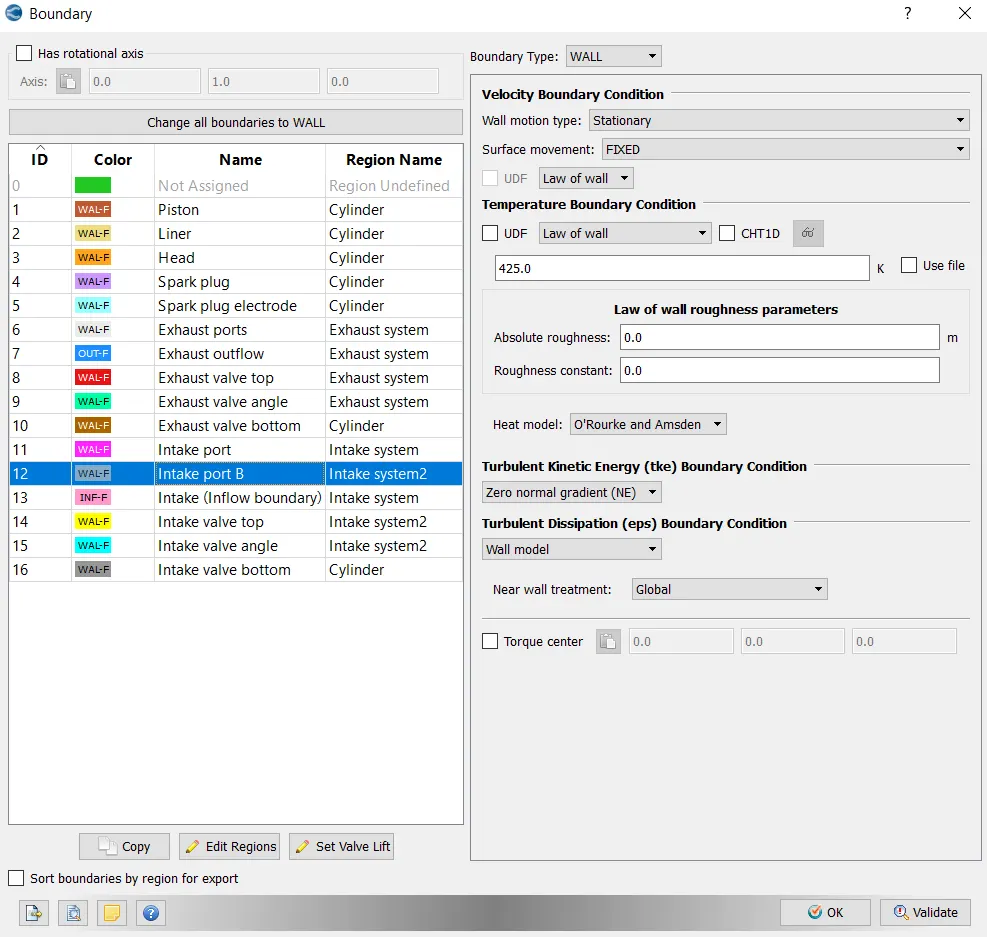
- Intake port - 2 temperature 425K
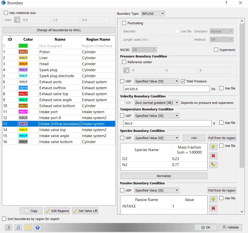
- Inflow pressure - 1 bar total pressure
- Inflow temperature - 363K
- Inflow species - Air
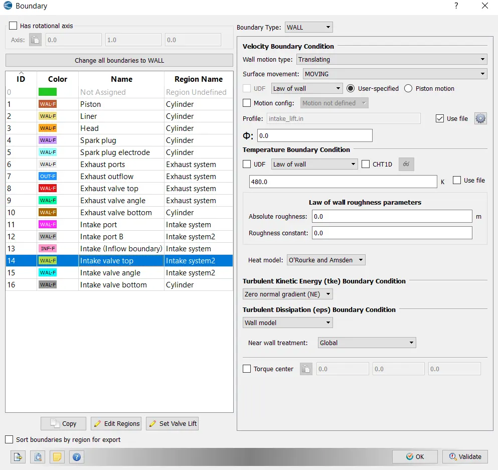
- Intake valve top temperature - 480K
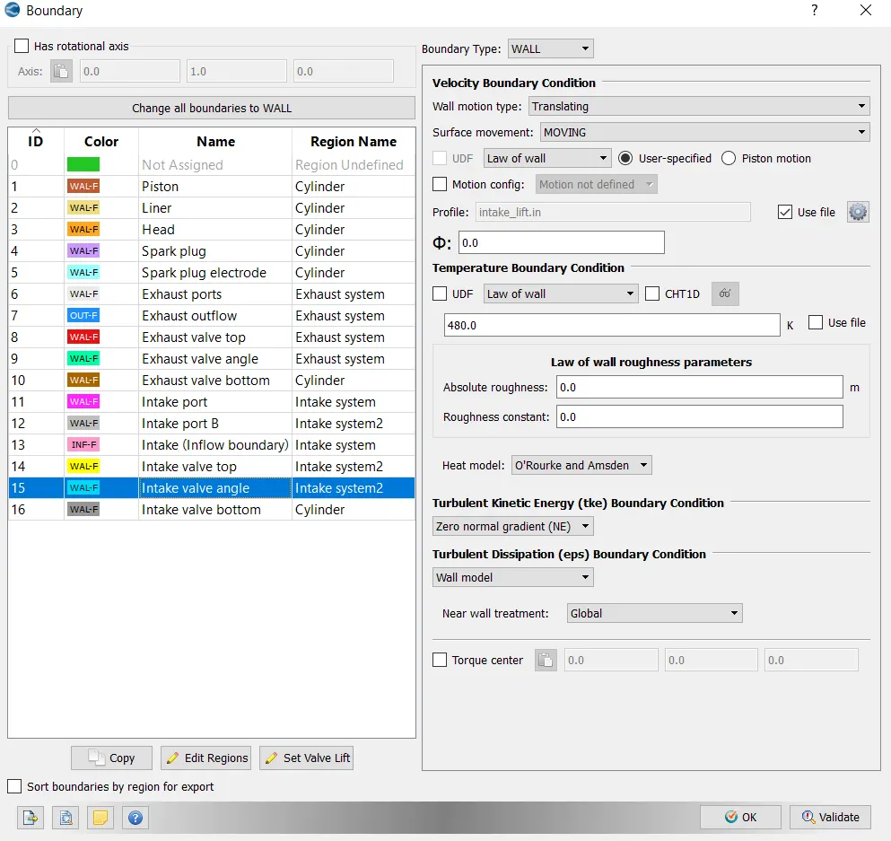
- Intake valve angle temperature - 480K
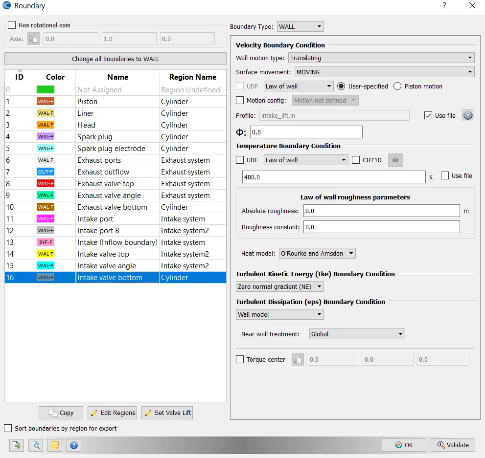
- Intake valve bottom temeprature - 480K
Initial conditions
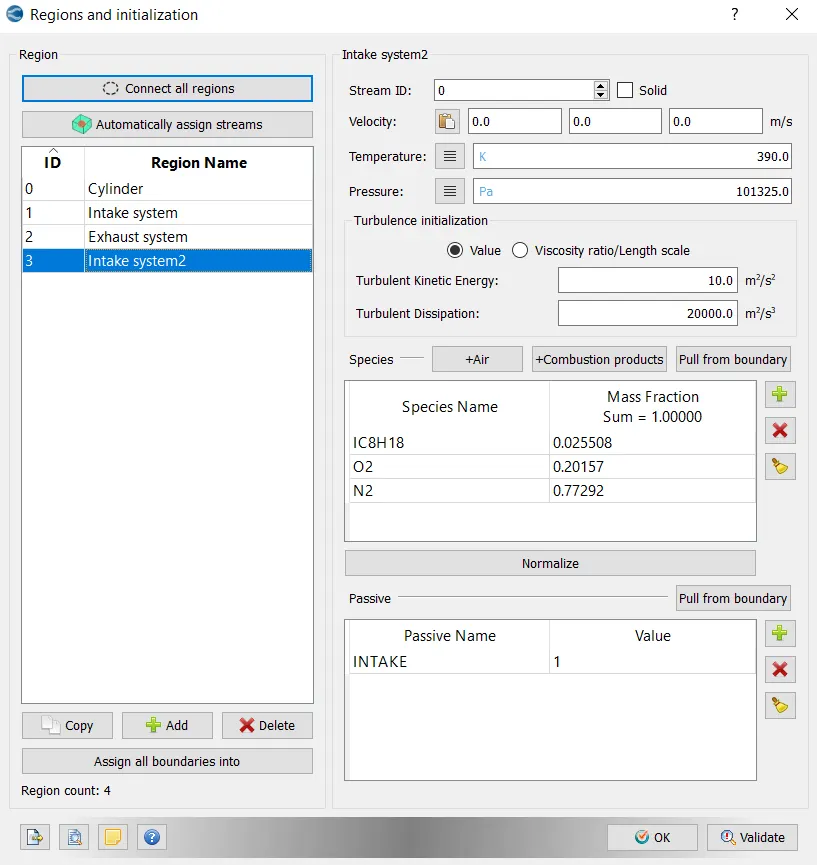
- Intake port - 1 (closer to combustion chamber)
- ic8h18 - 0.025508
- o2 - 0.20157
- n2 - 0.77292
- Temperature - 390k
- pressure - 1 bar
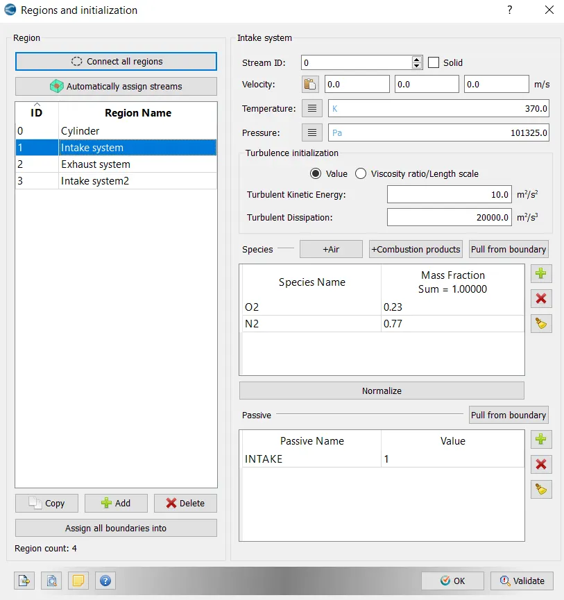
- Intake port - 2 (away from combustion chamber)
- Air
- Temperature - 370K
- Pressure - 1 bar
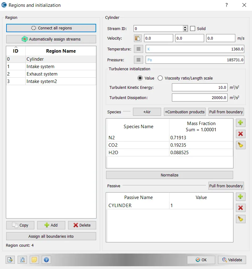
- Cylinder
- Pressure - 1.85731 bar
- Temperature - 1360K
- Stoichiometric composition
Injection Parameters
- Fuel flow rate = 7.5e-4 Kg/second
- Injection start time = -480.0
- Injection duration = 191.2
- Fuel temperature = 330K
Nozzle positions
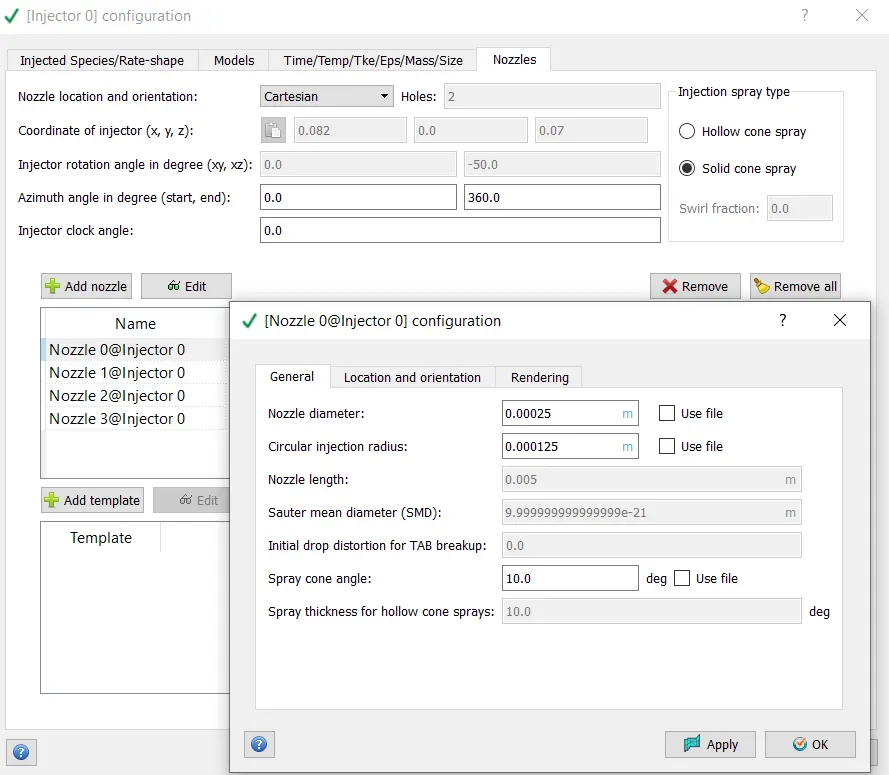
Nozzle diameter = 250 micro-meter
Circular injection radius = Nozzle radius
Spray cone angle = 10
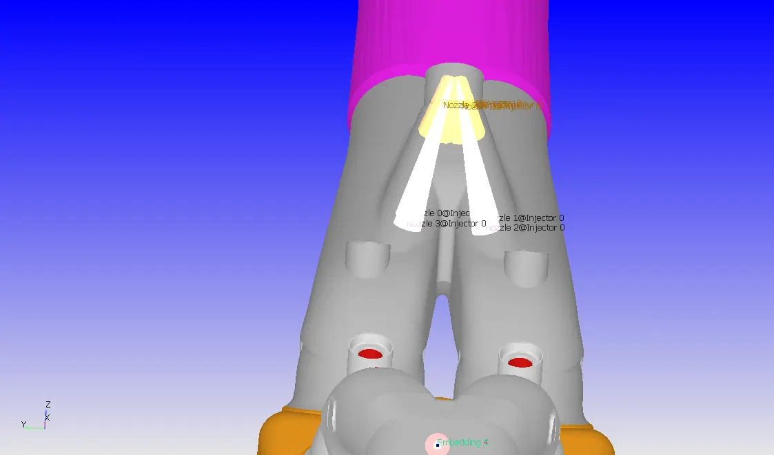
- Nozzle 0
- center 0.0823357 0.00100001 0.07019
- Align Vector -0.732501 0.210489 -0.647408
- Nozzle 1
- center 0.0823357 -0.00099999 0.07019
- Align Vector -0.732501 -0.210489 -0.647408
- Nozzle 2
- center 0.0823357 -0.0004 0.07019
- Align Vector -0.5 -0.2 -0.647408
- Nozzle 3
- center 0.0823357 0.0003 0.07019
- Align Vector -0.5 0.2 -0.647408
Spark Ignition Parameters
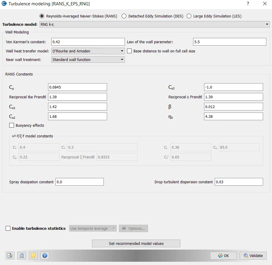
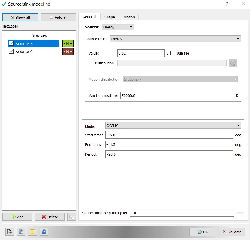
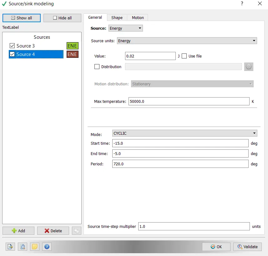
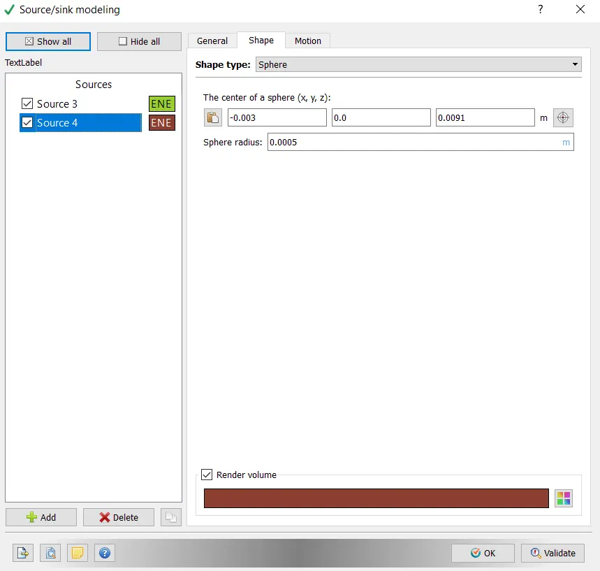
- Start of spark = -15 deg
- Spark duration = 10 deg
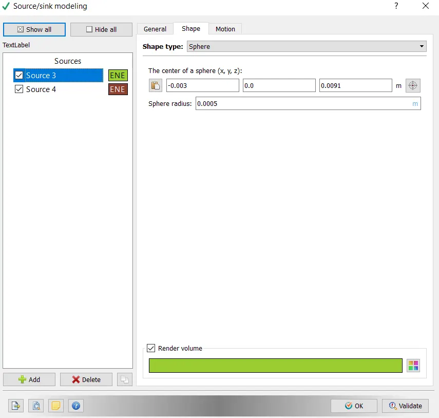
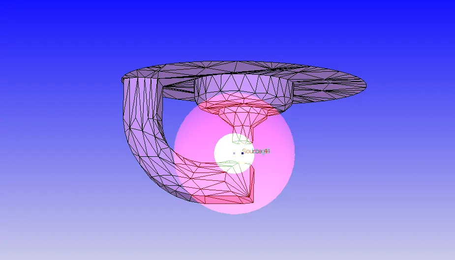
- Spark location = -0.003 0 0.0091
- Spark radius = 0.0005m
Procedure:
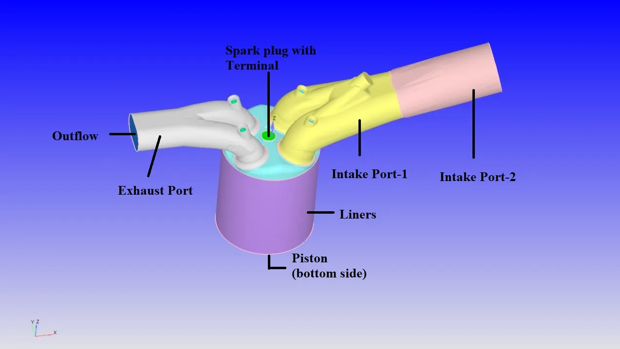
Initially import the geometry in Converge.
Now check if the complete geometry is imported or not. Once it is successfully done, go to Diagnosis > click on Find to diagnosis the geometry and it will display the 'Problem Triangles' (errors).
On running the Diagnosis we can see there are many errors in the geometry, which doesnot allow us to run the simulation. To overcome these issue we need to fix these. Before fixing them, we need to flag all the parts in the geometry appropiately. Then once the boundary flagging is done all the errors are visualized and overcomed.
Boundary Flagging:-
To start the process, we need to flag the boundaries and as we flag them we can easly hide the necessary parts easly. This helps us to geometry clean up more effectively. Initially boundary flaging is done for all the parts, later once the surface preparation is done then we can readjust the way we have done the boundary flaging.
Inorder to create Boundary flaging, go to Geometry > Boundary > Flag >create required Boundary Definitions.
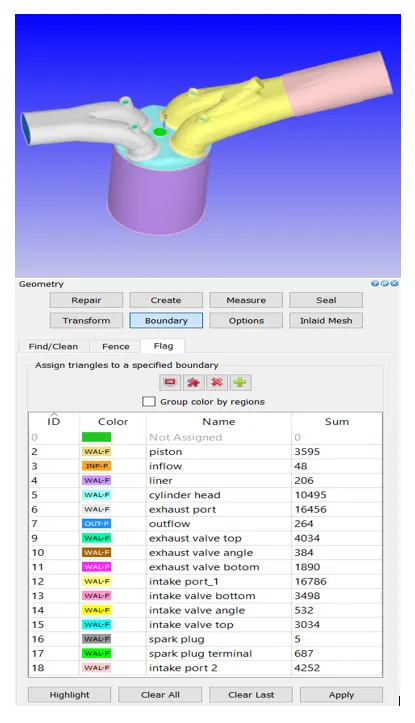
First assign the boundary that doesn’t have any problem triangles. As we have various parts in the geometry, Boundary Fence option can be used to separate the interface between two connected parts. Parts of PFI Engine is described as follows:
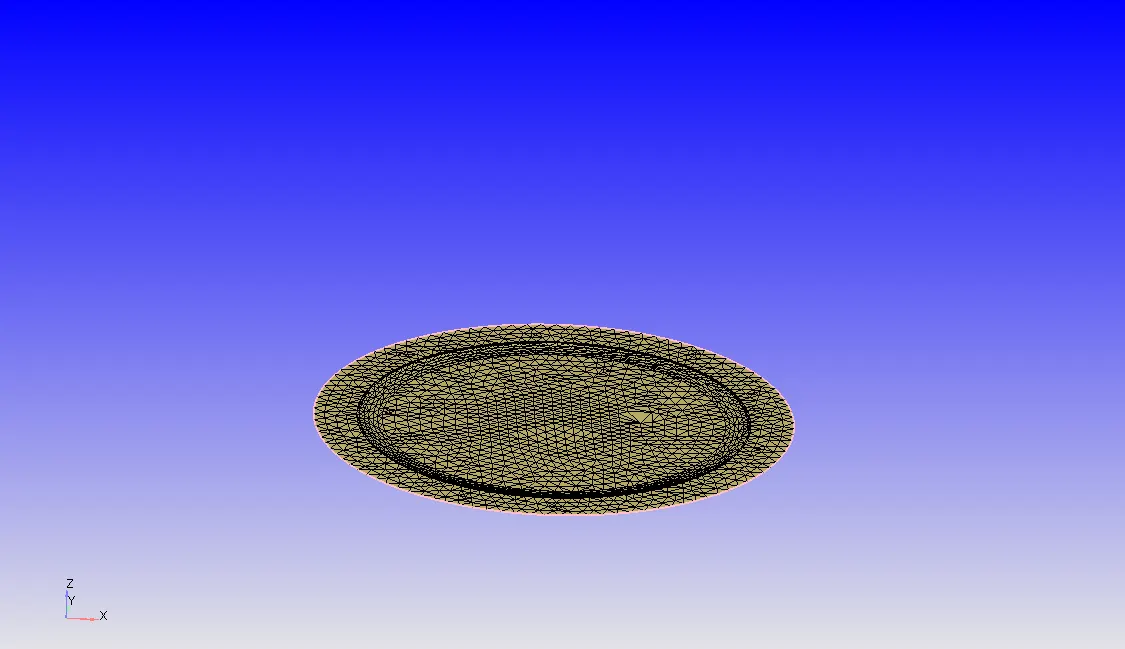
Piston:
A piston is a moving disk enclosed in a cylinder which is made gas-tight by piston rings. The disk moves inside the cylinder as a liquid or gas inside the cylinder expands and contracts. A piston aids in the transformation of heat energy into mechanical work and vise versa too. A piston acts as a movable end of the combustion chamber. Pistons are commonly made of Aluminium alloy for good and lightweight thermal conductivity. Thermal conductivity is the ability of a material to conduct and transfer heat.
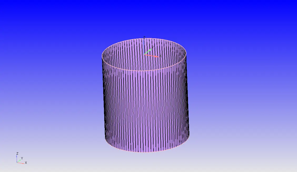
Liner:
A cylinder liner is a cylindrical part that is fitted into an engine block. It is one of the most important functional parts to make up the interior of an engine. Also called as Cylindrical sleeve. THese liners serves as the inner wall of the cylinder and acts as a sliding surface for the piston rings while retaining the lubricant within. The cylinder liners receives combustion heat through the piston and piston rings and transmits the heat to the coolant. These liners prevent the compressed gas and combustion gas from escaping outside. It is necessary that a cylinder liner which is hard to transform by high pressure and temperature in the cylinder.
Cylinder Head:
A cylinder head is usually located on the top of the engine block. It serves as a housing for components such as intake and exhaust valves, combustion chambers etc. It closes in the top of the cylinder, forming the combustion chamber. This joint is sealed by a head gasket.In most of the engines, the head provides space for the passangers that feed air and fuel to the cylinder and that allow the exhaust to escape. The head can also be a place to mount the valves, spark plug and fuel injectors.
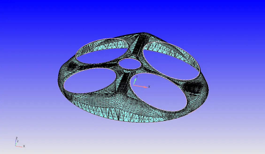
Exhaust Port:
The passage in the cylinder head which connects the exhaust valve and the exhaust manifold. The exhaust gases pass through the port to the exhaust manifold or header.
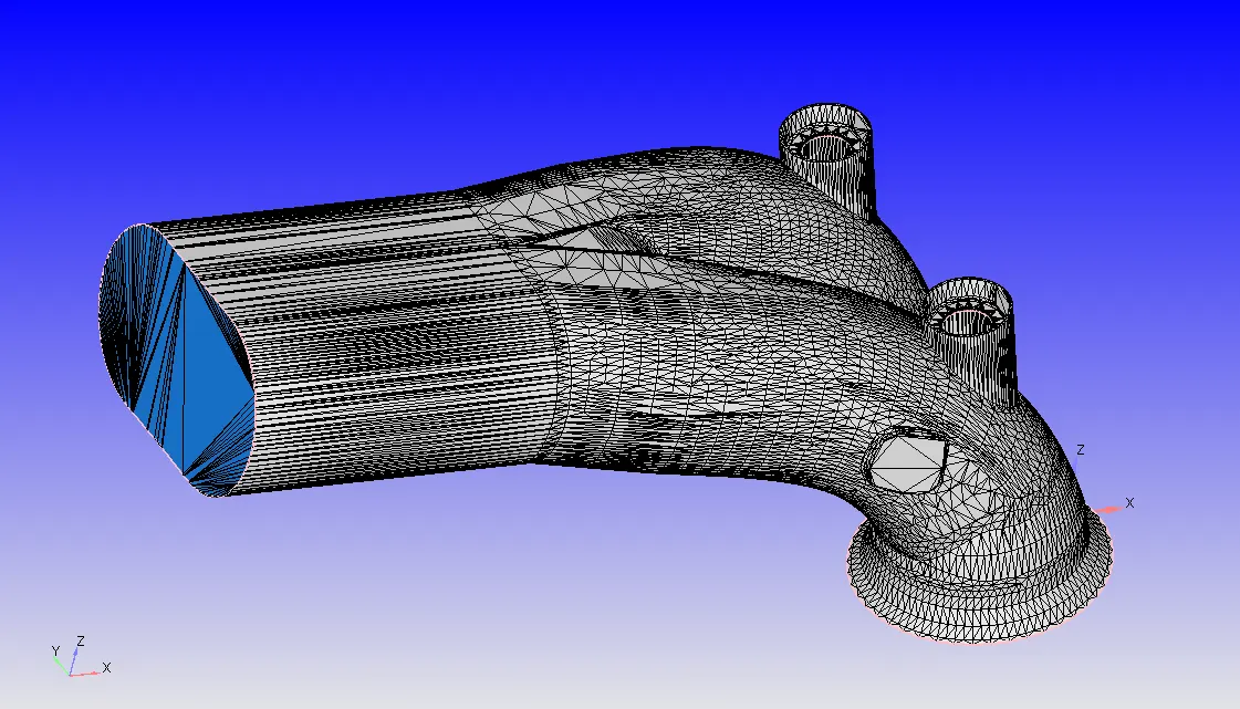
Intake Port:
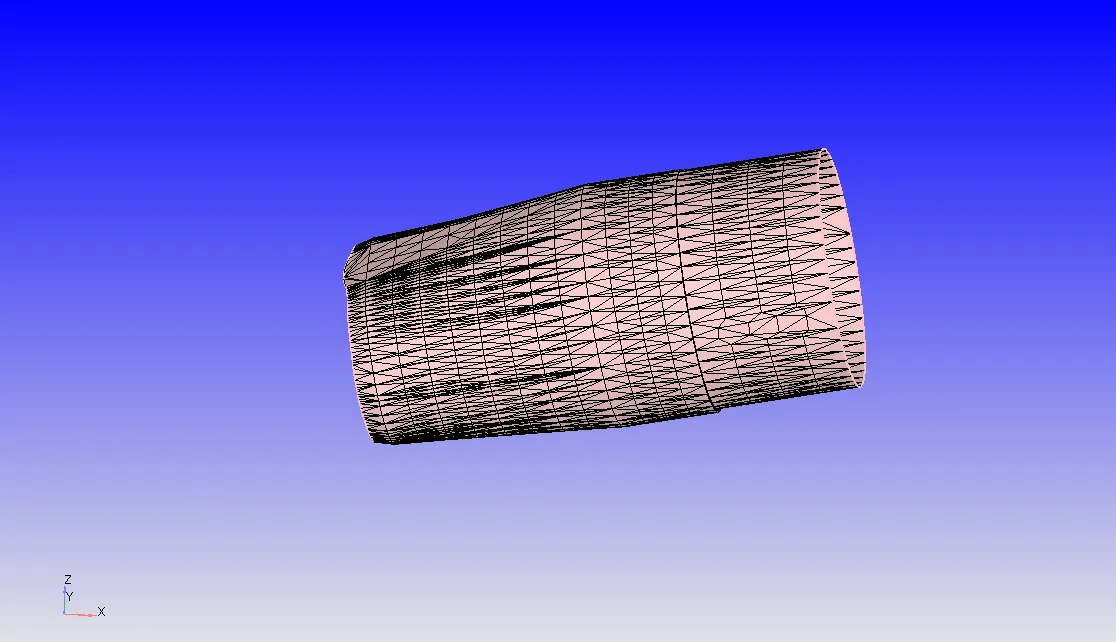
The passage in the cylinder head which connects the intake manifold to the intake valve through which the air-fuel mixture proceeds on its way to the cylinders.
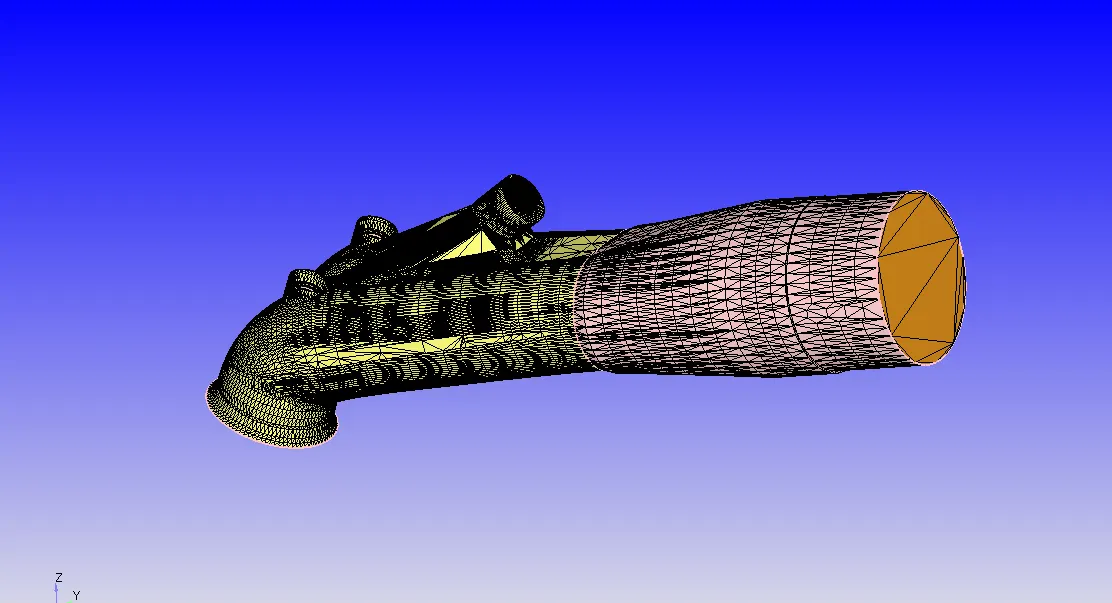
In this case, for boundary flaging we have divided into various parts i.e.
Intake port-1
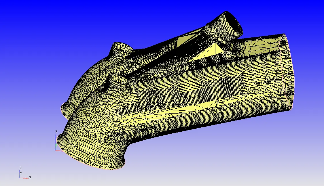
Intake port-2
Intake and Exhaust Valves:
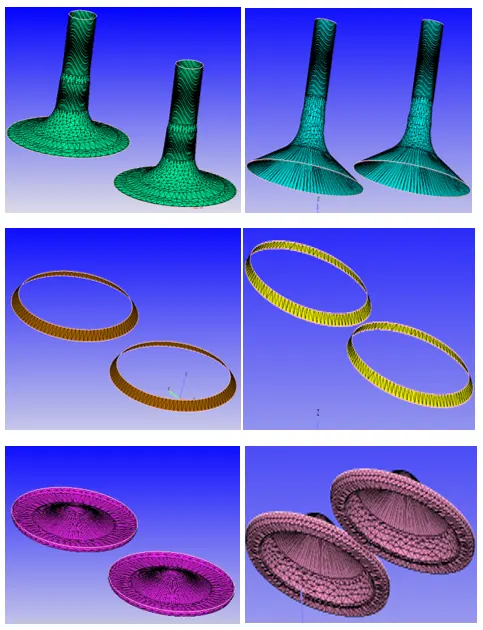
Valves are located in the cylinder head. Main function of the engine valves is to let air in and out of the cylinders. This air is used to help ignite the fuel which will drive the pistons up and down.There aretwo types of engine valves i.e. intake and exhaust valves. The intake valves let the air to flow into the chamber and the exhaust valves let the exhaust air to come out of the chamber. Among commonly used sleeve, sliding, rotary and poppet type valves, the popet-valve is common as it offers reasonable weight, good strength and good heat transfer characteristics.
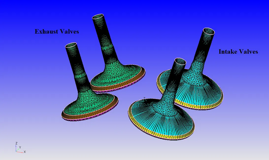
In order to controll the intake and exhaust perfectly, the intake and exhaust valves are flagged with different boundary names. This helps to set valve operation correctly and effectively.
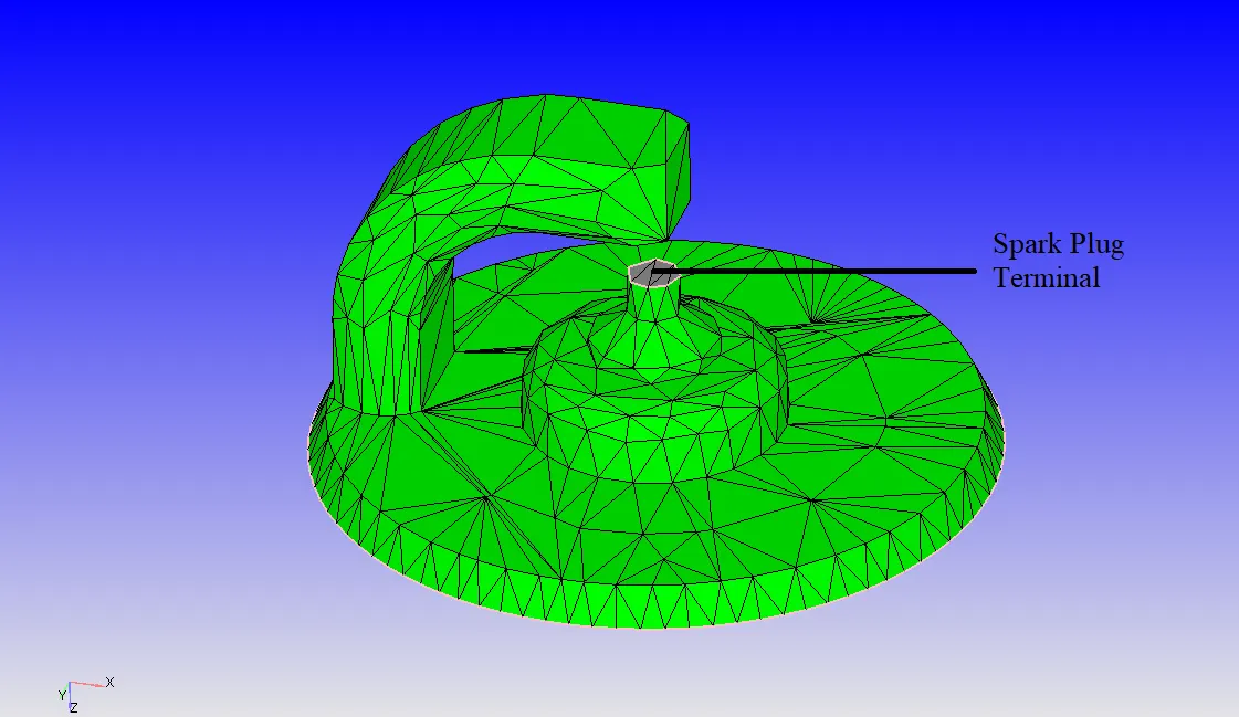
Spark Plug with plug terminal:
A spark plug is a device that delivers electric current from an ignition system to the combustion chamber of a spark ignition engine to ignite the compressed fuel/air mixture by an electric spark. Spark plug consists of a terminal which as a connector to the ignition system.
Surface Preparation: -
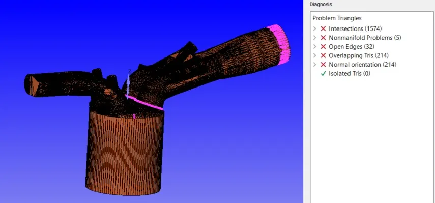
In surface preparation, all the errors found during diagnosis are fixed perfectly so that it helps us to get better results. Here on selecting the different problems from diagnosis window we can see where exactly the problem is in the geometry. In order to proceed the simulation all th errors/problems should be resolved. To inspect if the error is resolved go to Diagnosis > click on Find. When we try to remove the error at each step we need to Run Diagnosis and check if they are resolved. If all the problems are resolved then it shows the following output when we run the Diagnosis;
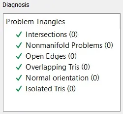
Once this is successful we can check all the boundary flagging and start setting up the case. The procedure follows;
Case Setup:
Application Type-
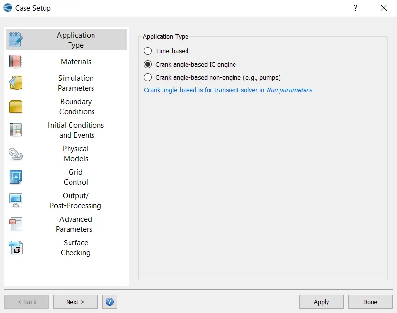
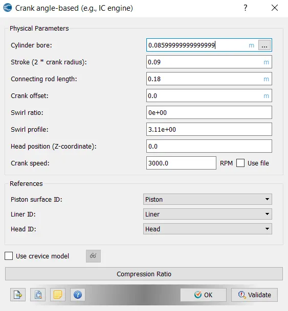
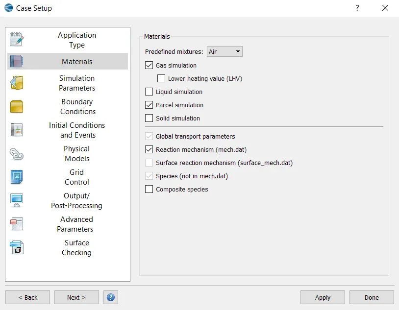
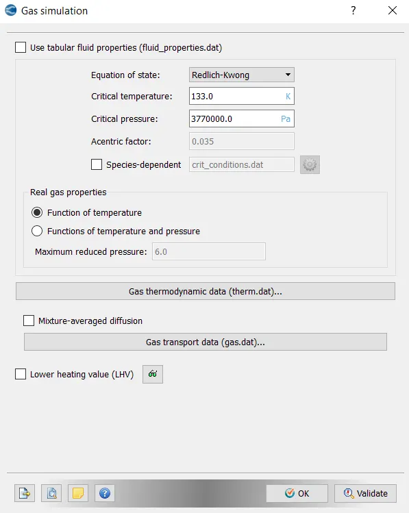
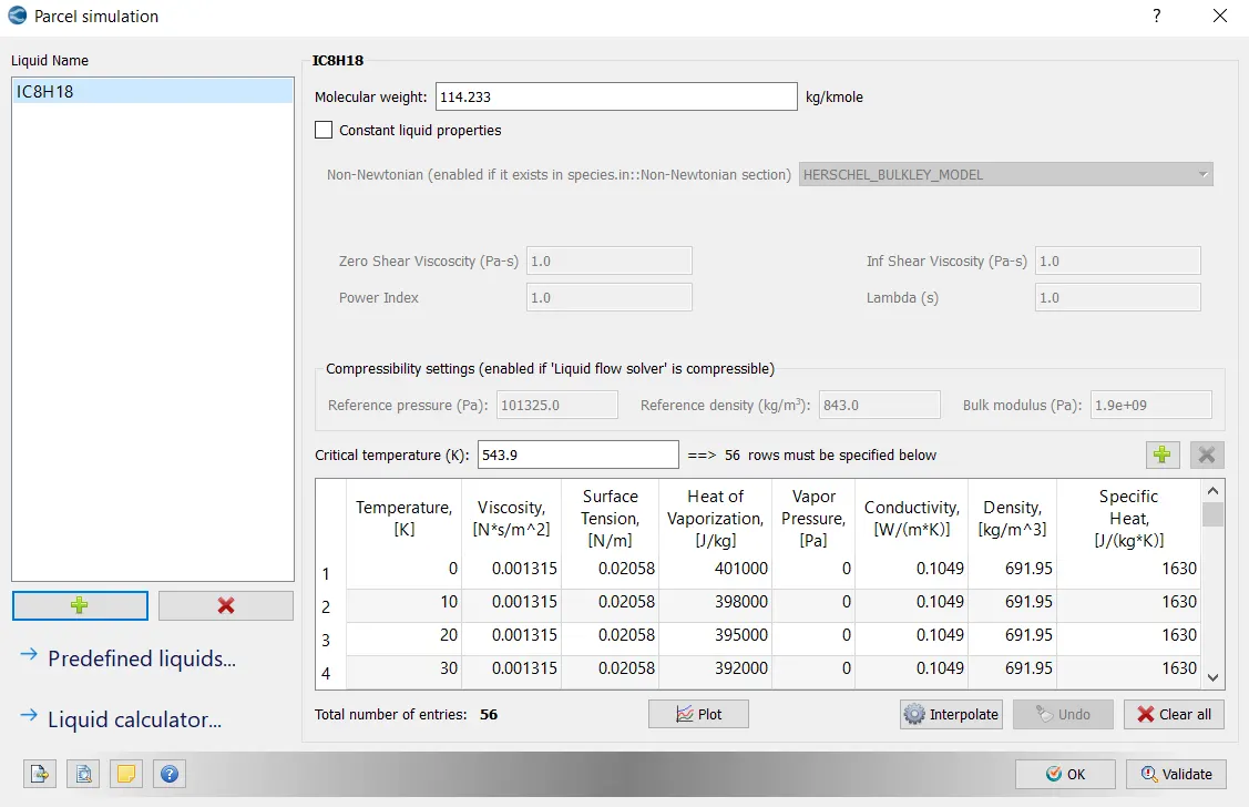
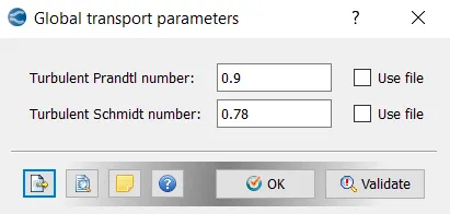
Materials-
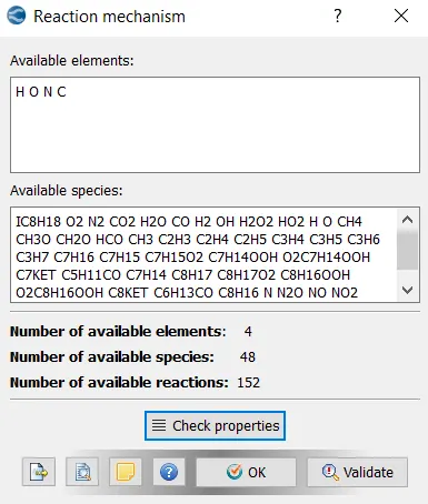
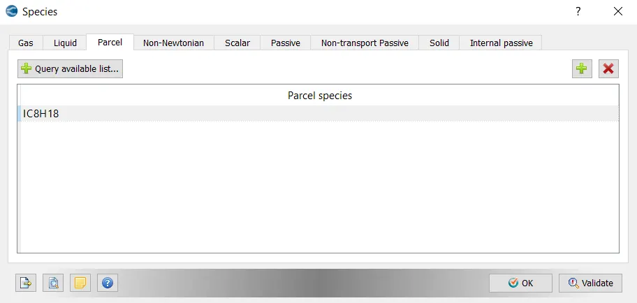
Simulation Parameters-
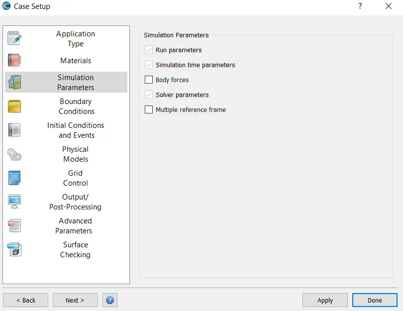
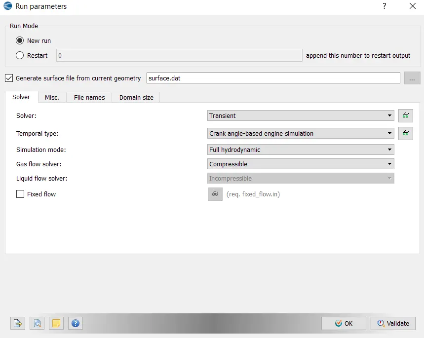
Boundary Conditions-
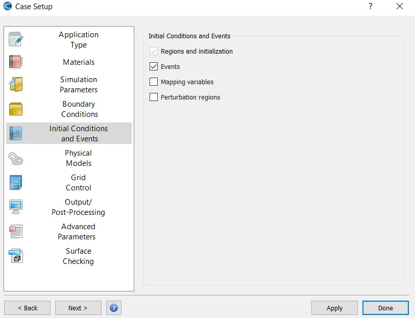
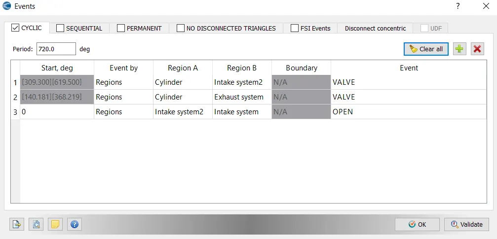
Initial Conditions and Events-
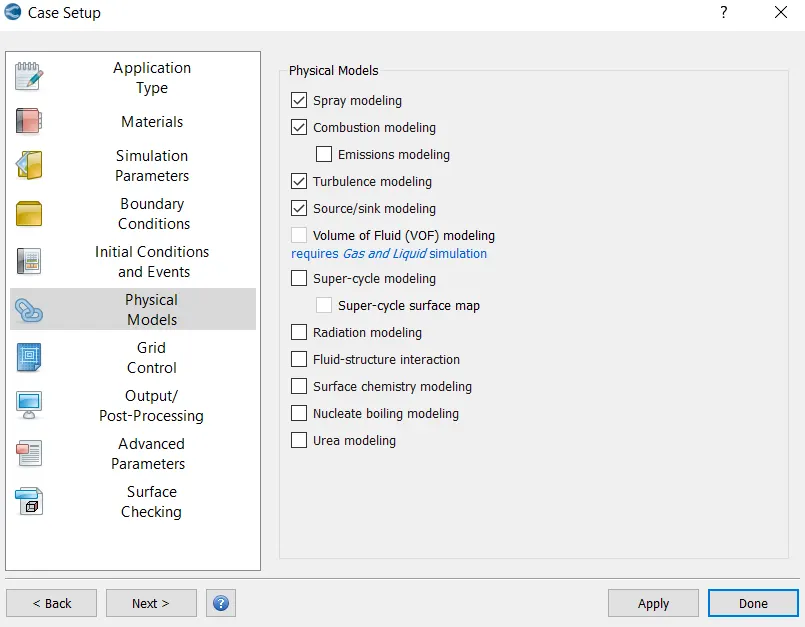
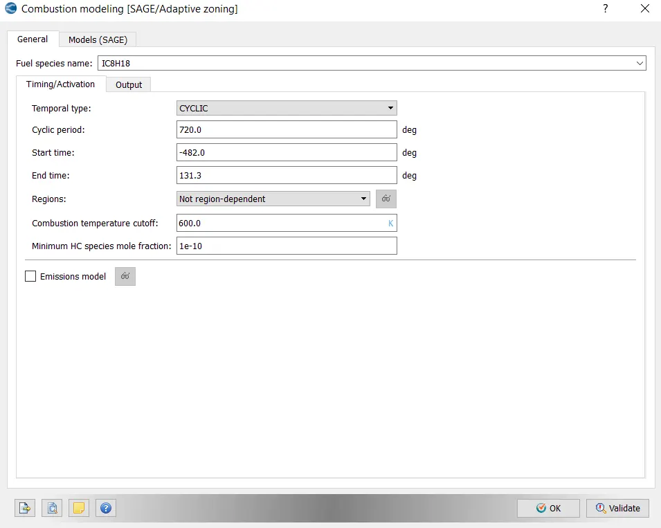
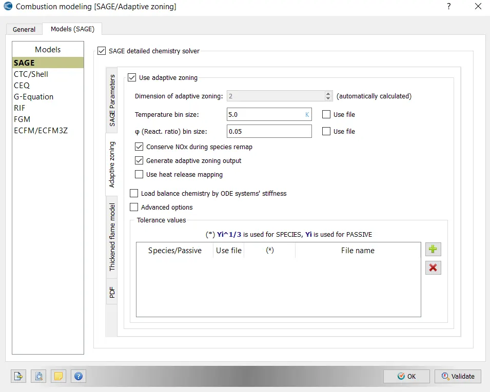
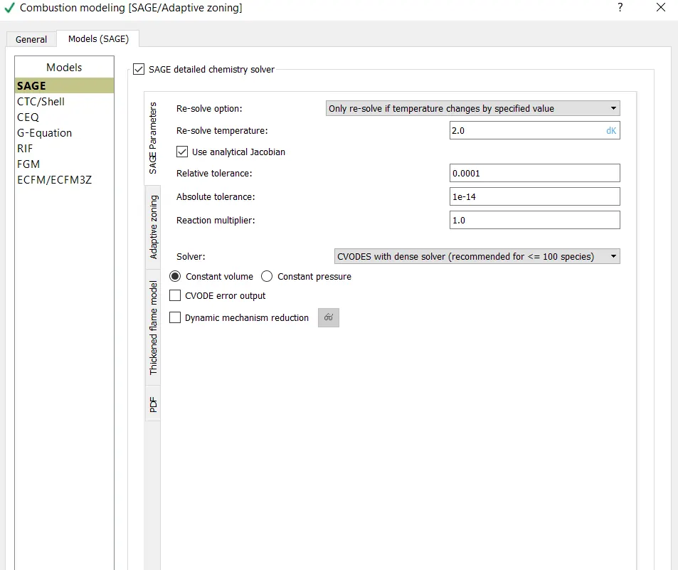
Physical Models-
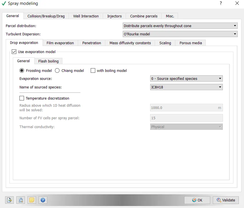
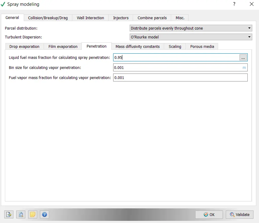
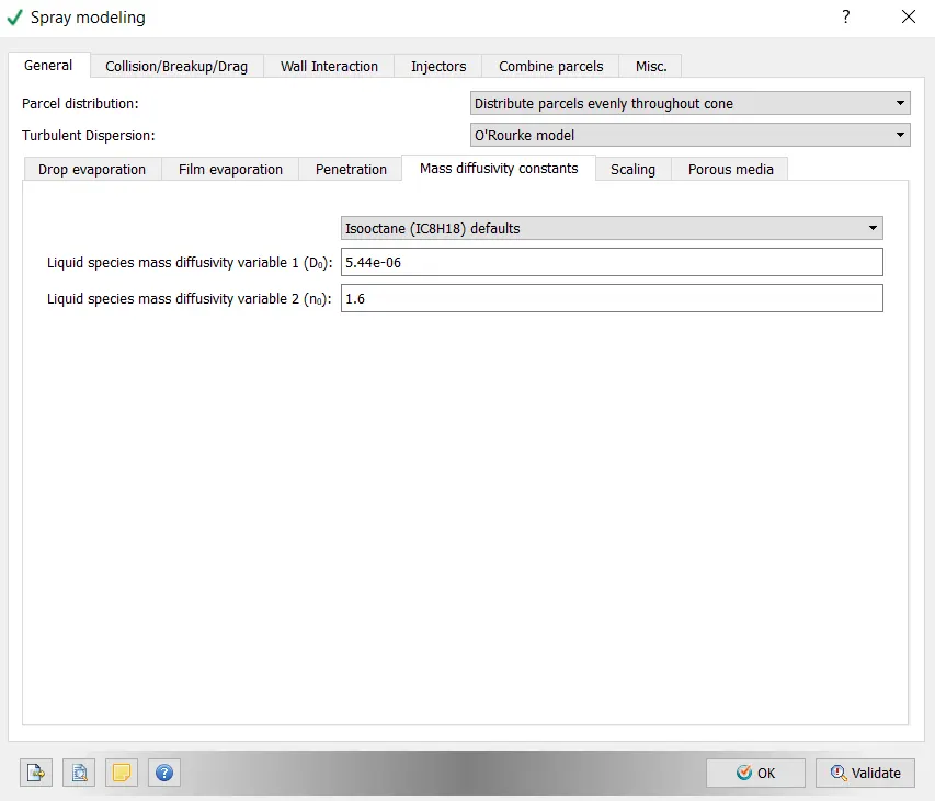
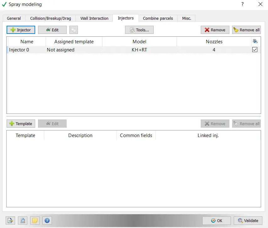
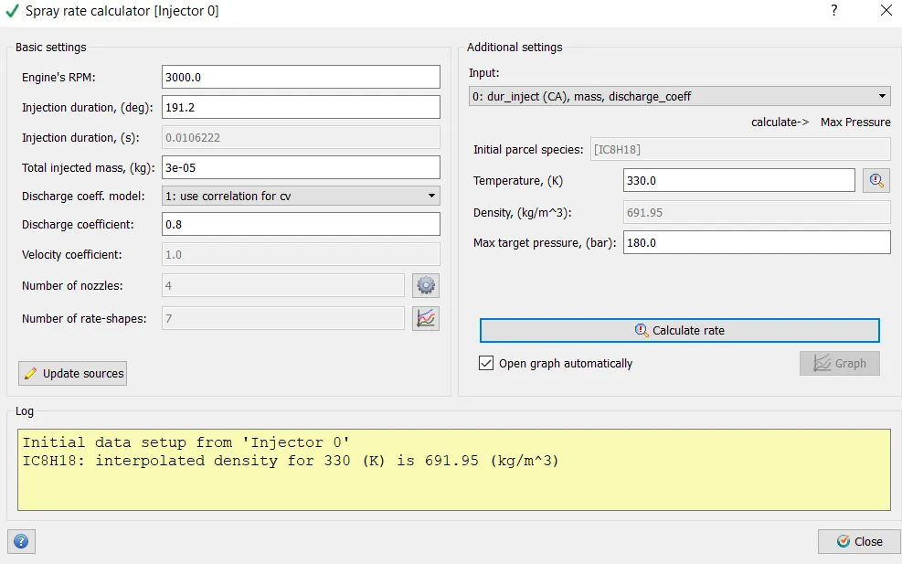
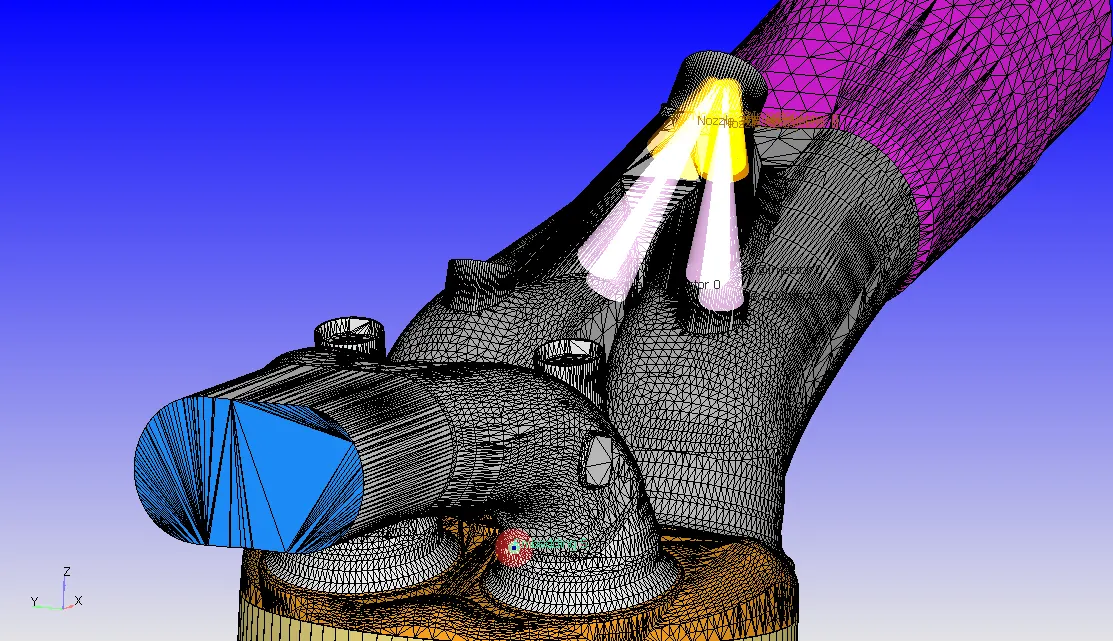
>> Go to Spray Modeling - select Injector 0 - click Edit - go to Nozzles - select each injector then click Edit and add th evalues for various parameters.
>> Go to Spray Modeling - select Injectors - click on Edit - Set the parameters.
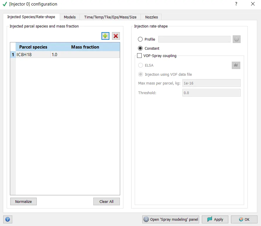
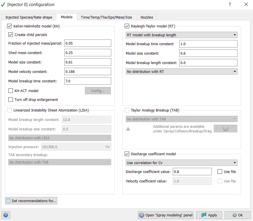
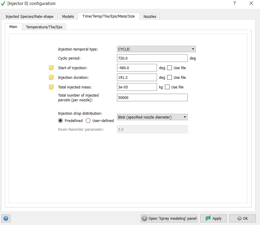
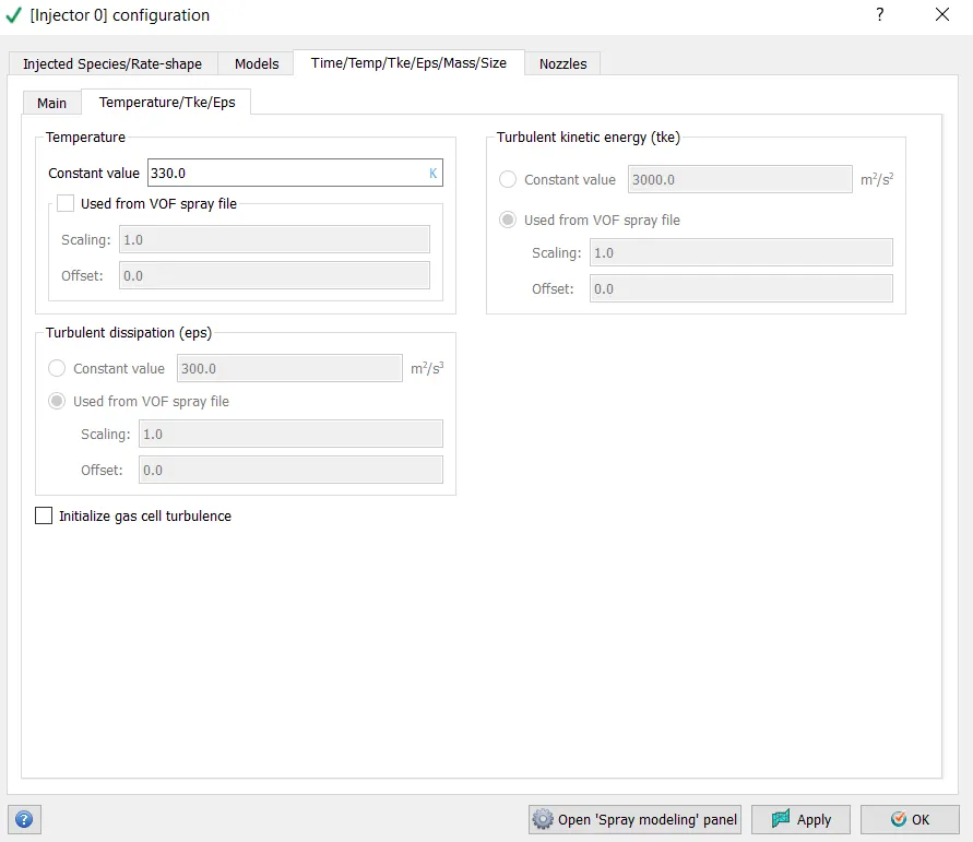
>> Go to Spray Modeling - select Injectors - click on Tools - select Spray Rate Preview.
Source/Sink Modeling-
Grid Control-
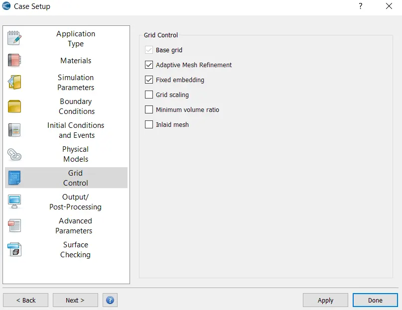
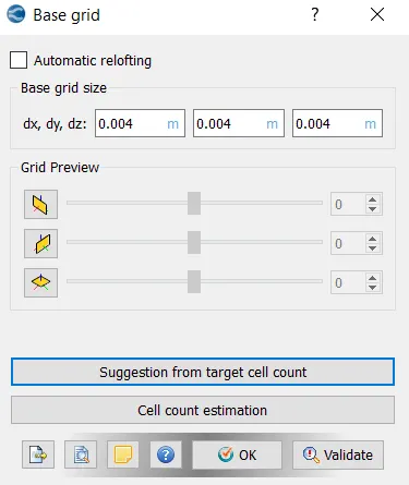
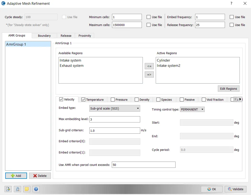
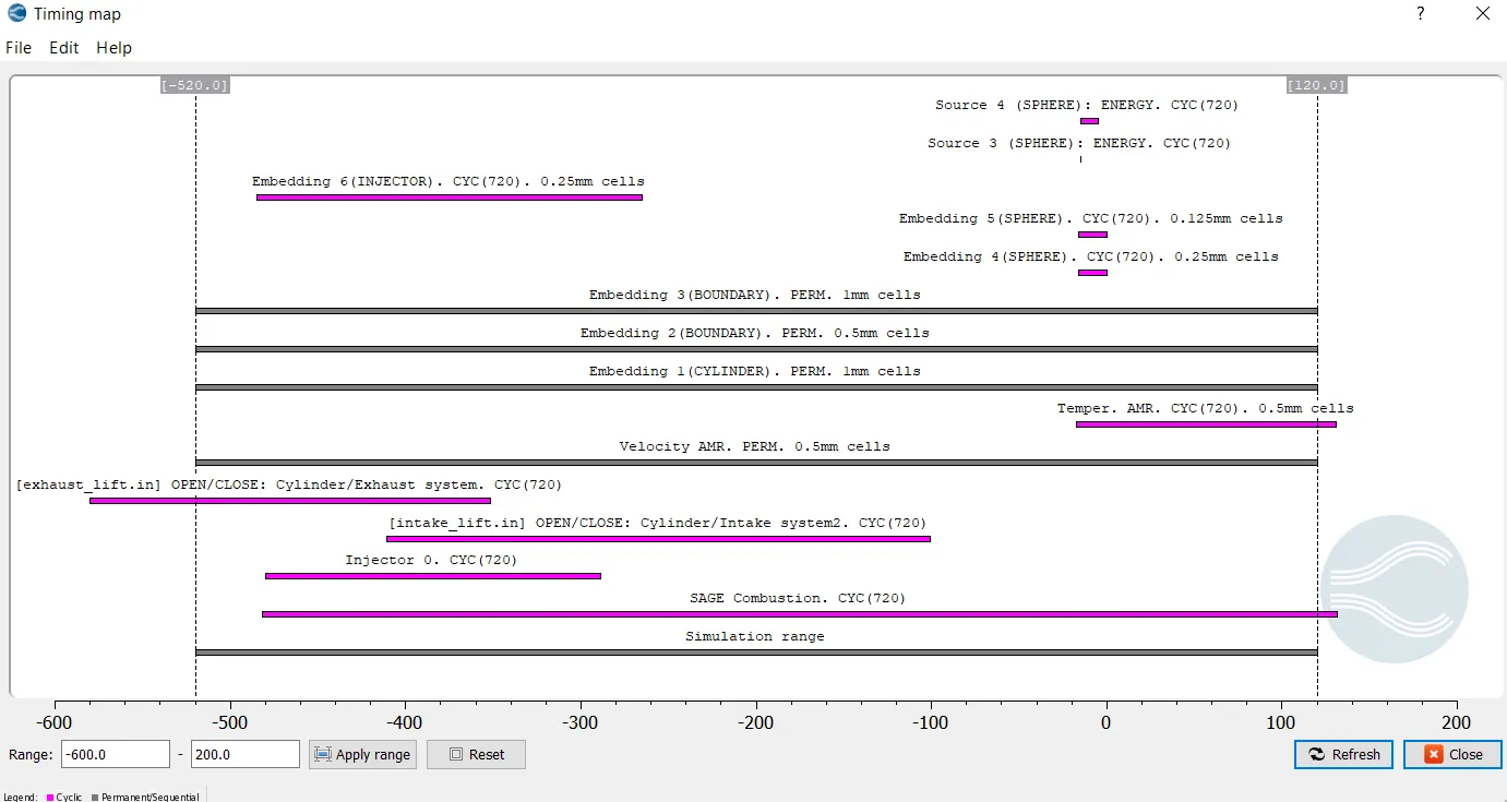
>> Right click on Adaptive Mesh and click on Timing Map.
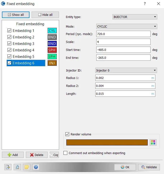
Cylinder Embedding:
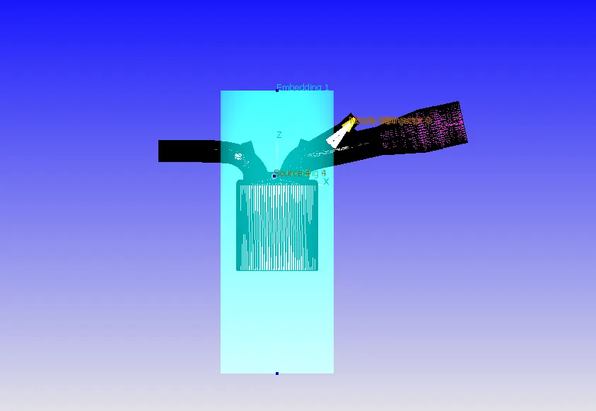
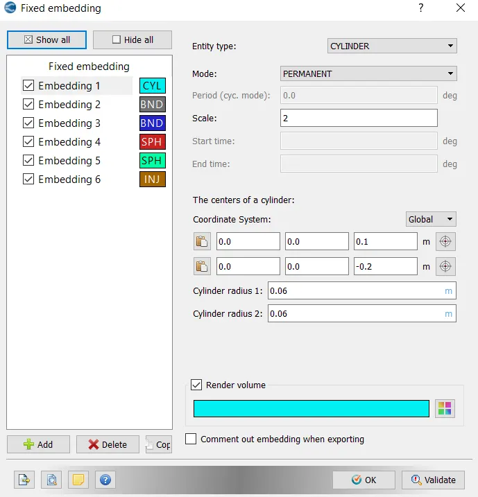
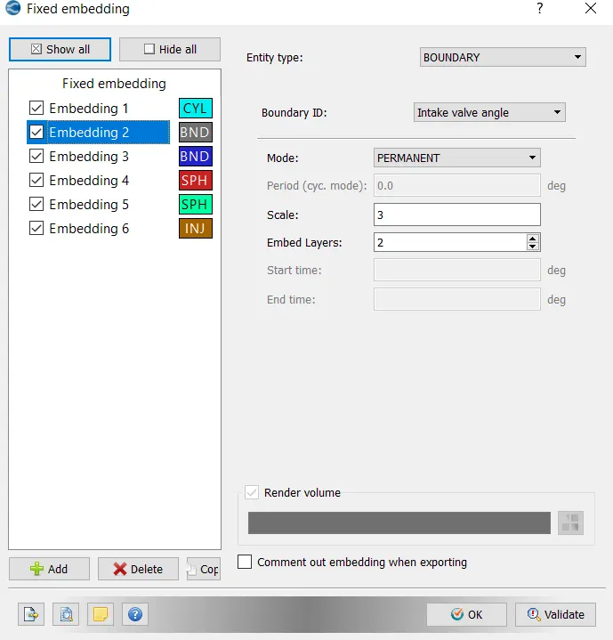
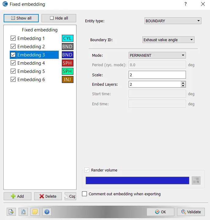
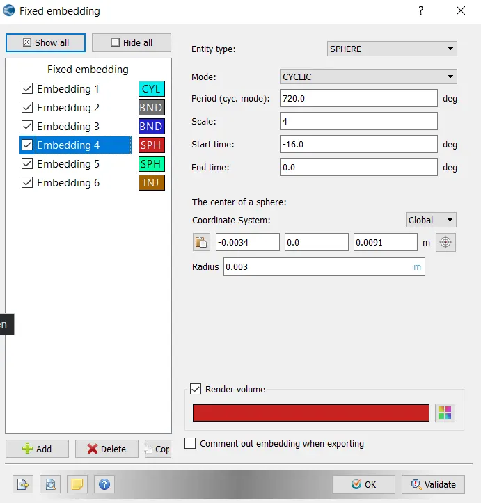
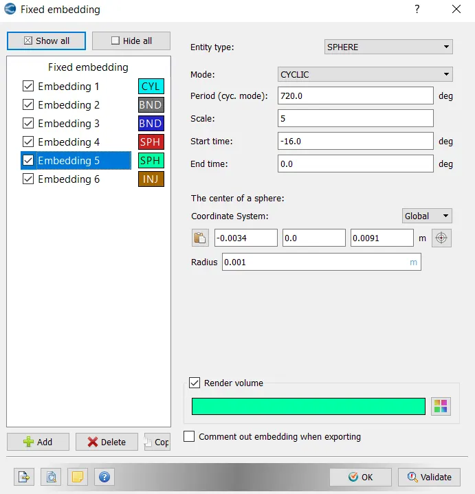
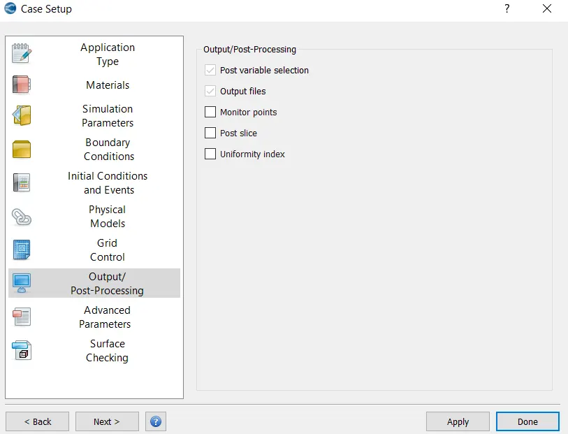
Output/Post-Processing-
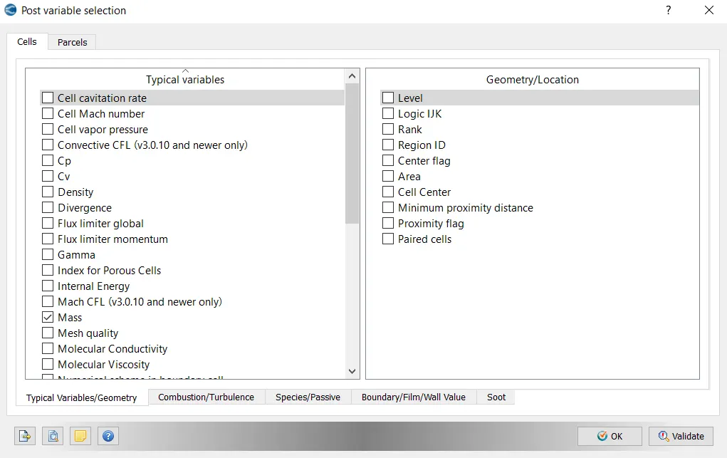
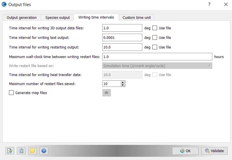
With this setting up of the case is complete and now go to Files > Export > click on Export Input Files. Select the destination folder (test) to save the data. Run the simulation using Cygwin and then we obtain the result(output files) in ".OUT File" format. In order to import these files into paraview we need to convert these files.
Steps to convert:
Go to C-drive > Programme files > select 'Convergent_Science' > 'CONVERGE' > 3.0.15 > open 'Utilities' > copy the 4th file i.e. " post_convert_30_msmpi_64".
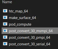
Now paste that file in the 'OUTPUT Folder'. Then direct to the OUTPUT Folder, double click on the copied file (post_convert_30_msmpi_64). Follow the steps by entering the numbers in command window and proceed till the files start converting.
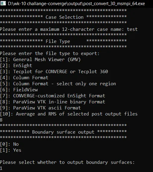
Once the files are coverted, ".VTM File " from the Output is used to open the geometry file in Paraview. Hence Contours are generated and animations are created. The same output files are used in converge to generate various plots.
Results:
Geometry- 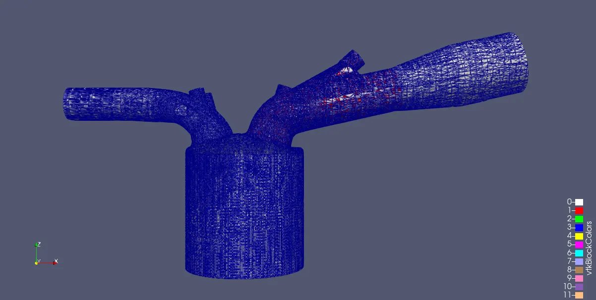
Meshing-
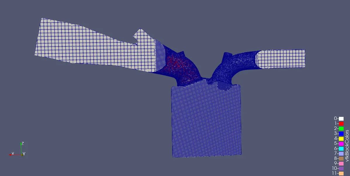
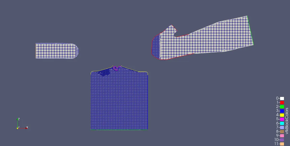
Plots:
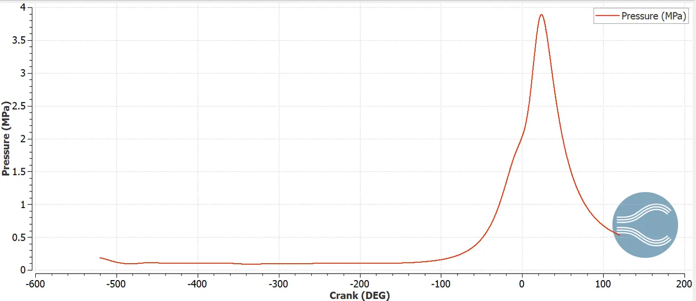
Pressure Plot-
The compression in the cylinder has raised or increased the pressure to the maximum value of 3.8MPa. Because of the expansion phase, it is observed that the pressure decreases rapidly.
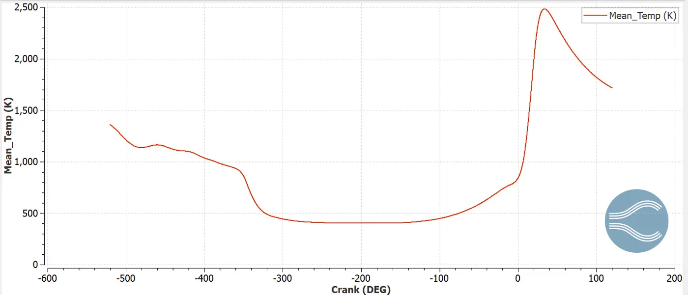
Mean temperature Plot-
Heat transfer in engines has the major effect on the engine performance.Here spark ignites the compressed air-fuel mixtureand the flame propagates in the complete system.The mean temperature in the compression stage reaches the maximum value of close to 2500 K.
Heat Release Rate Plot-
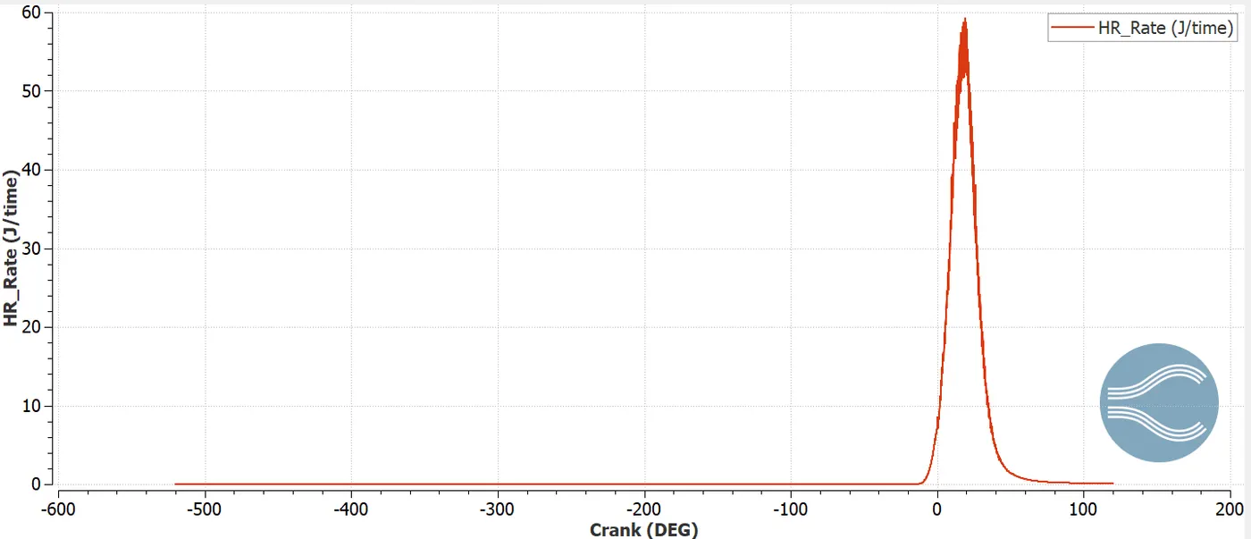
The plot indicates the heat released throught the period of cycle. Generally heat release is increased once the combustion start and decreases at the end of the cycle. It is observed that heat release is zero for maximum crank angles and its only maximum at a particular point is because at that point we provided the heat sourse for the model.
Volume Plot-
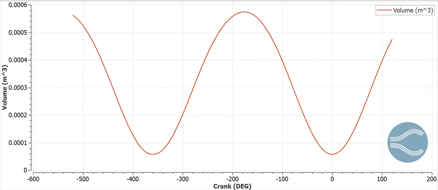
The total volume of the mixture is trapped inside the cylinder at a particular angleis depicted. Ratio of the maximum volume to the minimum volume indicates the compression ratio of the cylinder.
Cp Plot-
Cv Plot-
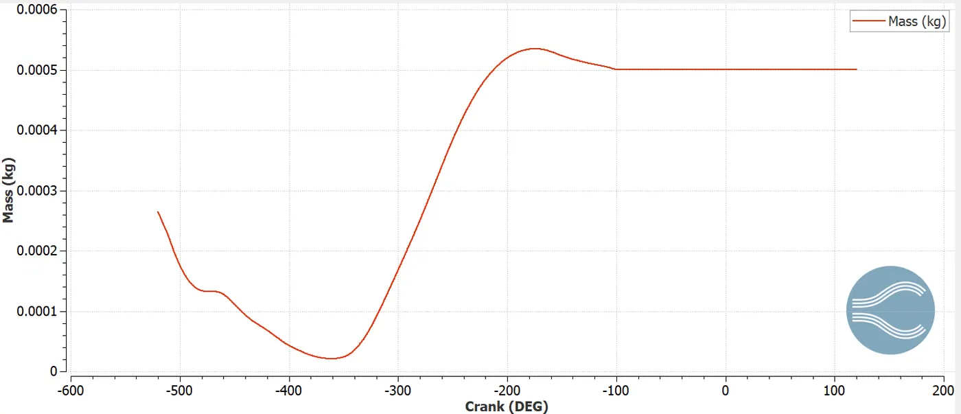
Mass Plot-
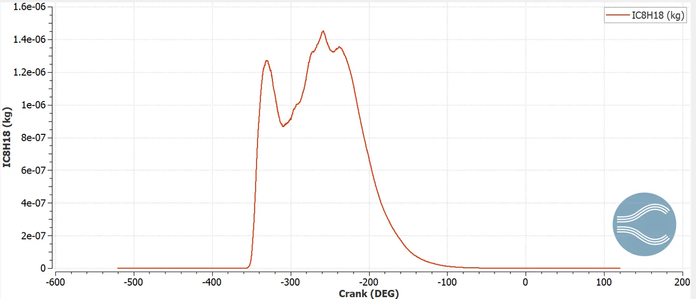
IC8H18 Plot-
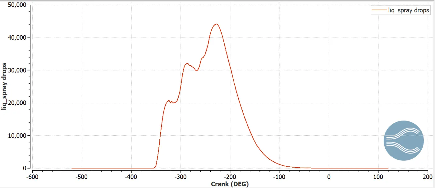
Liquid Spray Drops Plots-
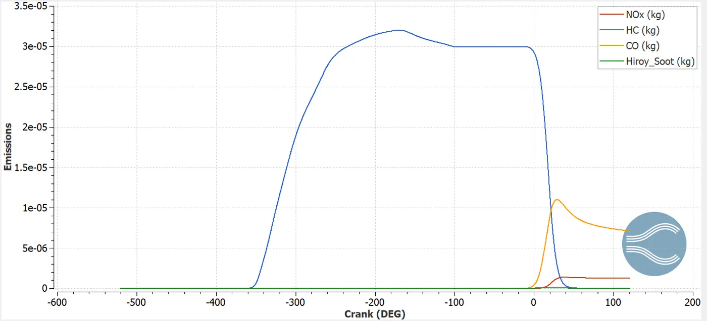
Emissions:
The below plot shows the behaviour of emissions. It concludes that at the end of the combustion CO content is much high compared to other pollutants and then flows as exhaust gases. In order to control these gases after treatment is done before they enter into the exhaust gas flow.
Compression Ratio of the Engine - The ratio of the maximum to the minimum volume of the space enclosed by the piston of an internal-combustion engine during the full stroke.
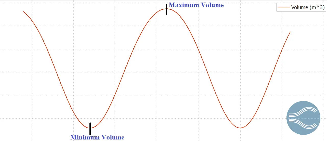
>> C.Ratio = (Maximum Cylinder Volume)/(Minimum Cylinder Volume)
>> C.Ratio = 0.000574/0.0000571
>> C.Ratio = 10.05
Necessity of a wall heat transfer model and Why can't we predict the wall temperature from the CFD simulation -
To perform good and accurate prediction of engine heat transfer and the wall temperature models are useful for accomplishing heat transfer from the hot gases to all th engine parts, also to the coolent and lubrication oil. In a IC engine during power stroke , the air-fuel mixture gets ignited by the spark plug and hence chemical reactions takes place in the chamber.These reactions raise the temperature inside the chamber and hence the forces the piston to expand. Important correlation are reviewed for three engine heat transfer approaches i.e. gas to wall, wall to wall, and wall to liquid heat transfer models. In order to get good prediction of wall temperature, all the three approaches must be coupled. Heat transfer is the passage of thermal energy from hot to cold region. This passage occurs in 3 different modes i.e. conduction, convection and radiation. Conduction is the diffusion process, here heat is transfered by the direct contact. Convection is associated to fluid motion. This is catorigized into natural convection and forced convection. In natural convection the fluid motion is generated by the heat transfer , the fluid close to the hot surface becomes lighter and raises. Whereas in forced convection the fluid motion is driven by external means. Radiation depends on the wave propagation process, here heat is transfered by means of elctromagnetic waves.
For the PFI engine simulations it takes lot of time to compute the case as it contains complex geometry.For this if we want to capture the heat transfer we need to solve energy equations should be solved to get convection of heat from fluid to solid surface. Hence this increases the computational time. for simulating the complex geometry it needs lot of time for computing the fluid part itself in transient case along with the combustion processes.Thus, it becomes difficult to predict the wall temperature for CFD simulationas solving of heat transfer along with Navier STokes equations which take more run time. Wall heat transfer models are used if we are focused only on the heat transfer by giving less preference to fluid motionsand the reactions. To maintain the good efficient operation proper cooling is provided at the walls.
Calculating the Combustion efficiency of this engine -
The combustion efficiency is a measurement of fuel being burned is being utilized in the combustion process. Complete combustion would result in 100% efficiency, but it is not possible, as there are some losses. Combustion efficiency is the fraction of the fuel that burns.
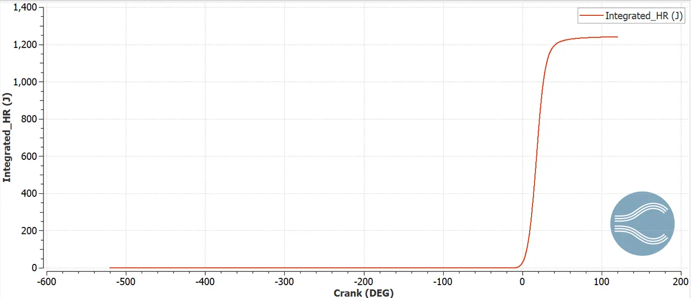
Mass of Fuel Injected=3e-05 Kg
Total heat release= 1241.1 Joules
Lower calorific value(LCV)= 44 MJ/k
Combustion efficiency=(Total heat released)/(Total energy content of fuel)
= (Total heat release)/(m)*(Lower Calorific Value )
= (1241.1)/[(3e-05)*(44e-6)]
Therefore, Combustion efficiency = 94.2%
To find Power and Torque using Engine Performance Calculator -
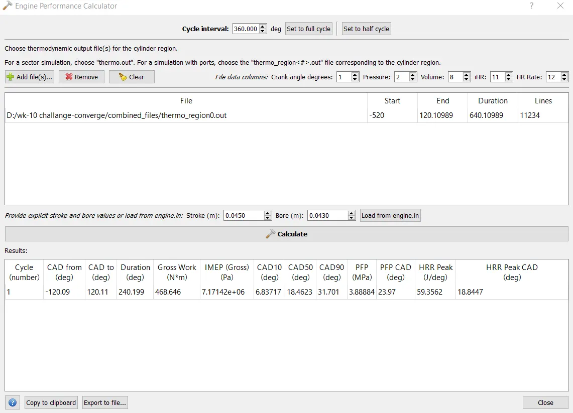
From above calculated result from calculator;
Gross Work= 468.646 N-m
Time Duration= 240.199 deg
Now, converting timein degrees to seconds.
Revolutions per minute=3000
Revolutions per second=3000/60 =50
Here, single rotation of Piston =360 degree
Rotation per second= 50*(360) = 18000 deg/sec
Time for combustion= Time Duration/Rotation per second
= 240.199/18000
= 0.0133 sec
>> Power(P)=(Work)/(Time)
= (468.646)/(0.0133)
Power = 35236.54 W or 35.23 KW
>> Take, Power(P) = (2*π*N*T)/60
T= (60* P)/(2*π*N)
T= (60 * 35236.54)/( 2*π*3000)
T=112.2 N-m
Significance of ca10, ca50 and ca90 -
- ca10, ca50 and ca90 are defined as the position of the crank angle (in degree) at which the cumulative heat release reaches at 10%, 50%, 90% respectively.
- ca10 represents the start of ignition, ca50 represents the end of air-fuel mixture combustion and at ca90 represents the end of combustion.
Animations:
Conclusion:
- Initially for the geometry boundary conditions are applied and surface preparation is carried out. Errors are removed and case setup for Full hydro are set throughly.
- Several plots are created to understand various parameters in th engine.
- Combustion efficiency of the engine is calculated.
- Compression ratio and wall heat transfer model are also studied to understand their importance.
- Power and torque are also calculated using engine performance calculator.
- Also significance of ca10, ca50 and ca90 is also studied.