Week 10: Project 1 - FULL HYDRO case set up (PFI)
OBJECTIVE : To run a full engine setup simulation using physical spray, combustion and Spark modelling for a PFI gassoline engine.
SOFTWARE USED: Converge V3.0 and Cygwin
LITERATURE :
The quest for high performances and low emissions leads engine manufactures to trim the operating range of
combustion devices near their stability limit. The capability of accurately simulate the engine in such a critical
conditions is indispensable and many steps are made, both in terms of CFD modeling and computational hardware
development.
There are above all two limits that restrict engine operation because of CCV: in the lower part-load range one
should mention the misfiring limit, which comes into play primarily in the course of high degrees of charge dilution
(residual gas, air) and the associated increase in cyclic fluctuations. At full load, on the other hand, the knock limit
restricts optimum-efficiency combustion control.
An internal combustion engine (ICE) is a heat engine in which the combustion of a fuel occurs with an oxidizer (usually air) in a combustion chamber that is an integral part of the working fluid flow circuit. In an internal combustion engine, the expansion of the high-temperature and high-pressure gases produced by combustion applies direct force to some component of the engine.
The term internal combustion engine usually refers to an engine in which combustion is intermitten, such as the more familiar 4 stroke and 2 stroke piston engines, along with variants, such as the 6 stroke piston engine and the wankel rotary engine.
Typically an ICE is fed with fossil fuels like natural gas or petroleum products such as gasoline, Diesel and Fuel oil. There is a growing usage of renewable Fuels like biodiesel for CI (compression ignition) engines and bioethanol or methanol for SI (spark ignition) engines.
For this simulation we have to run a full hydro simulation which consists of a spark ignition, Spray combustion chemicals as well.
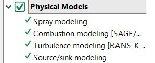
Setup
1. For this simulation the other parameters will remain the same. The only changes that will be made are in the physical models. These models are namely, spray modelling, Combustion modelling and sink Modelling.
Spray Modelling
For an IC Engine spray modelling is an important part. This determines how the spray will behave and the way it will be distributed and mixed with the fuel. The spray shaopoe can be basically in 2 types: spherical cone shapeed that has a hollow area and a distributuion which has a small area of mixing and contact eith the air.
For this simulation we used holloow spray in the center for even distribution of fuel and better mixing of fuel with air.
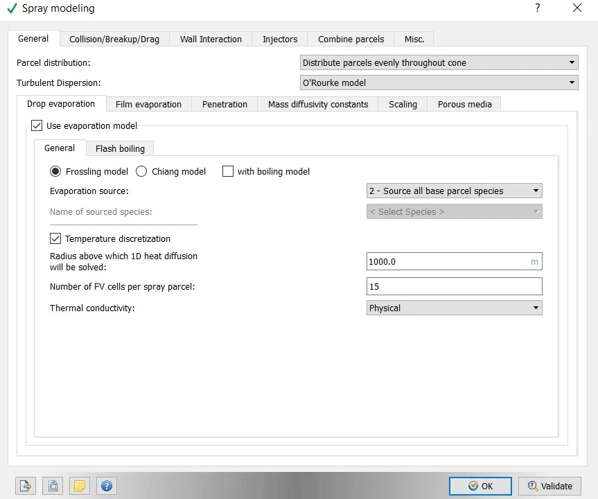
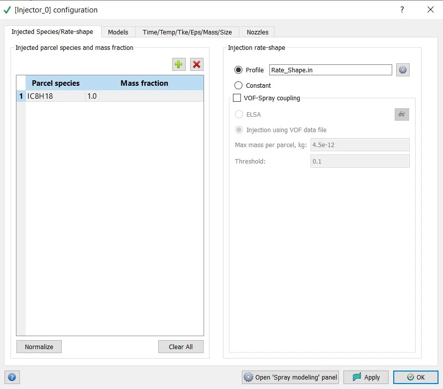
The above image shows the injector configurations of the PFI Engine.
The fuel is Basic Octane fuel.
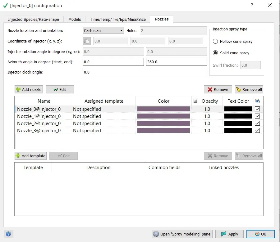
Nozzels Labelled.
For these nozzles we also had to assign the proper centres fro nozzle spray.
NOZZLE PARAMETERS
Nozzle diameter = 250 micro-meter
Circular injection radius = Nozzle radius
Spray cone angle = 10
- Nozzle 0
- center 0.0823357 0.00100001 0.07019
- Align Vector -0.732501 0.210489 -0.647408
- Nozzle 1
- center 0.0823357 -0.00099999 0.07019
- Align Vector -0.732501 -0.210489 -0.647408
- Nozzle 2
- center 0.0823357 -0.0004 0.07019
- Align Vector -0.5 -0.2 -0.647408
- Nozzle 3
- center 0.0823357 0.0003 0.07019
- Align Vector -0.5 0.2 -0.647408
Combustion Modelling
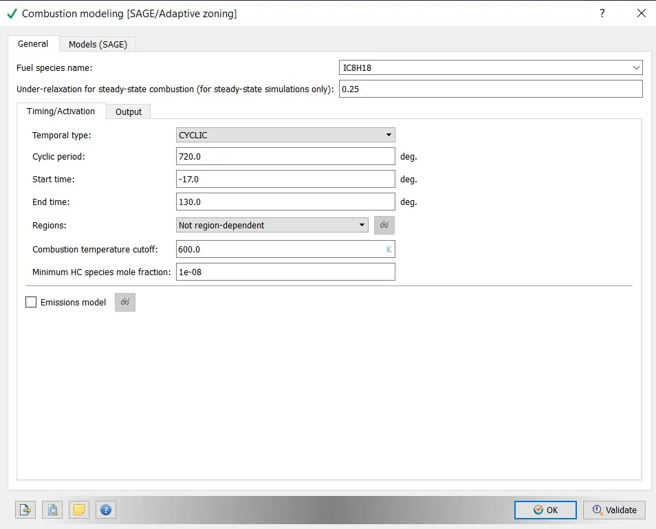
For the combustion model we have used the SAGE Model of combustion.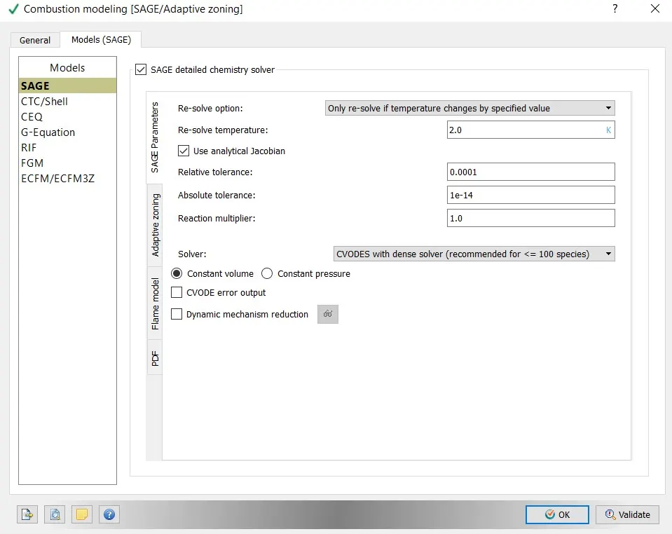
RESULTS
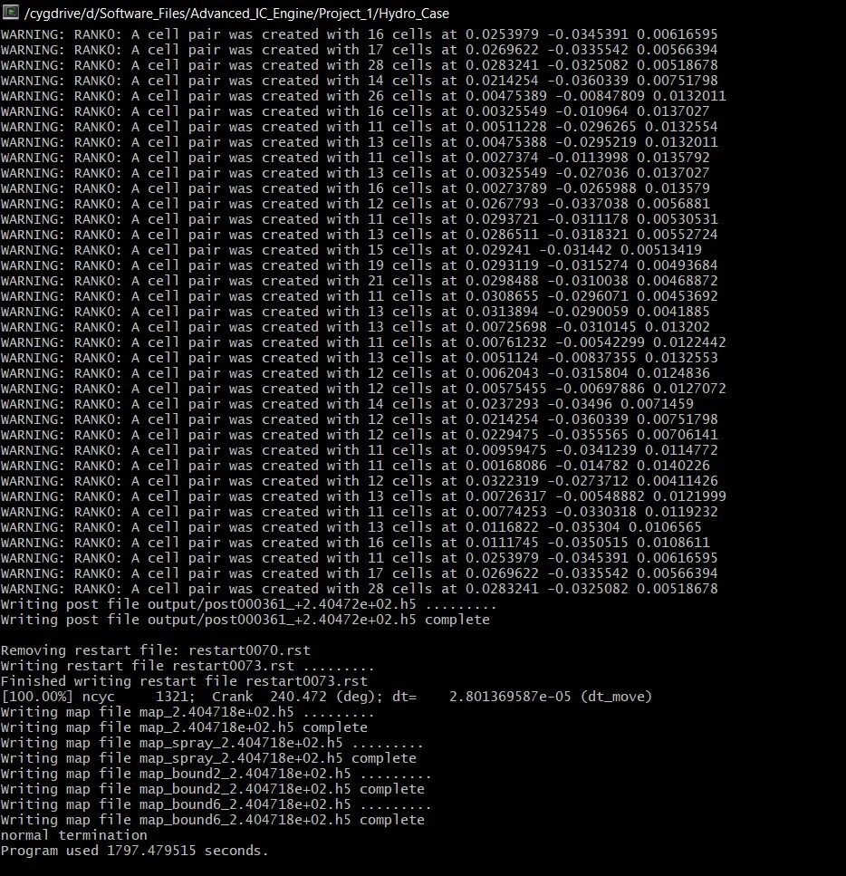
Simualtion run took about 1800 seconds.
We have taken a mesh size fo 8mm with certain embedding areas that would help refine the mesh and bring better results in certain areas.
Temperature Contour
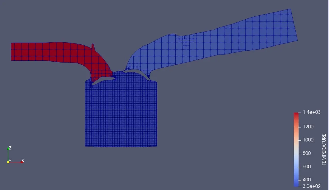
Temperature contour for the PFI Engine for full simulation run
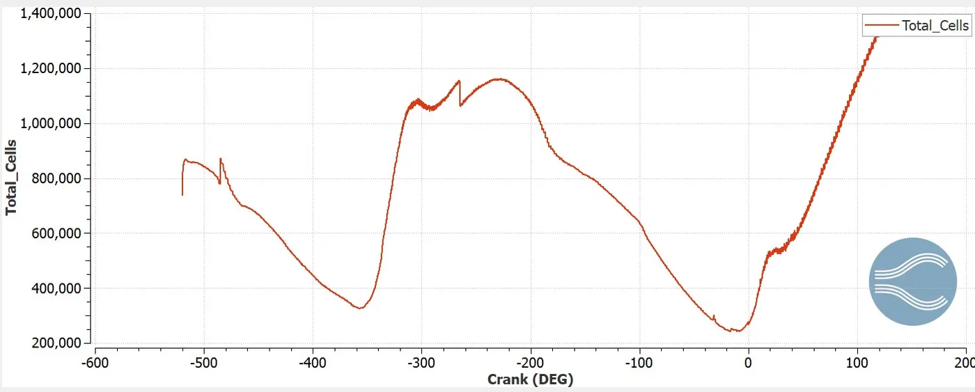
in the Above image we can see that the total number of cells that increases at zero degrees. This is at the point where the combustion process takes place and the total cells increases as we have also applied embedding to the geometry
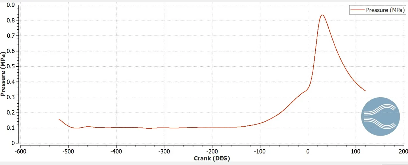
In the above graph we can see that the pressure we can see that the pressure rises up from about -150 crank angles. This is the point in a valve timing diagram where the intake valve is closed at the fuel is being injected to the cylinder. The point of the peak in the point of combustion where the pressure is about 0.8 Mpa.
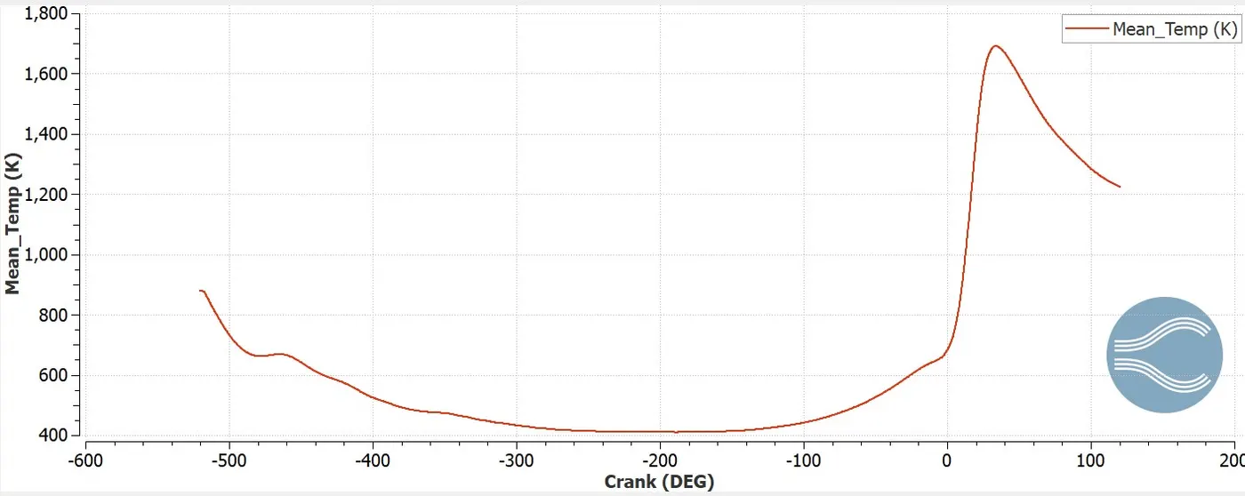
The maximum temperature for this engine is about 1700 k that is at the power stroke.
For any normal engine, the temperature rises up to about 1500K. For this engine the temperature goes up to more than that at the power stroke as the engine has 2 intake valves. This is because the intake valves sre supposed to be bigger thatn the exhaust valves .
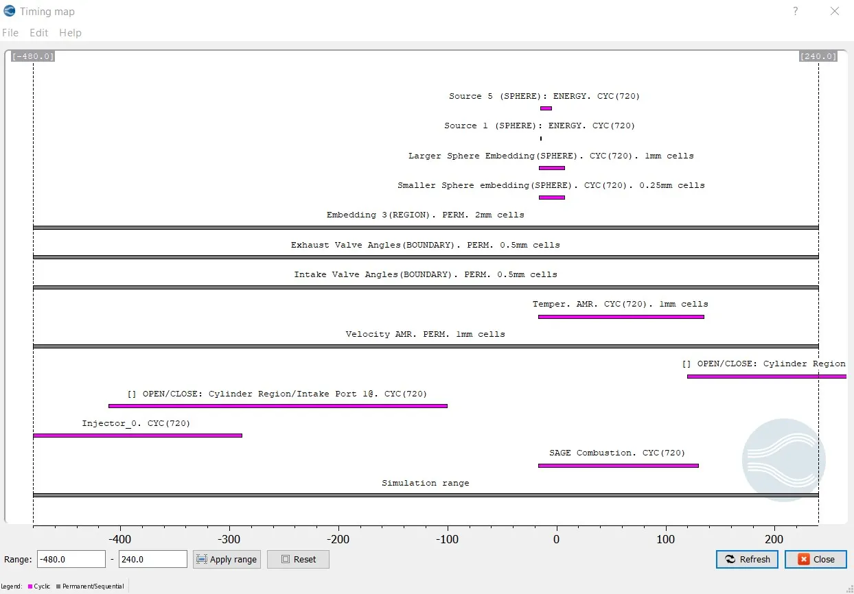
The above image is the timing map of the engine.
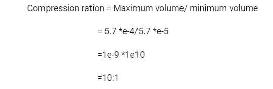
Q1. What is the compression ratio of this engine?
Q2. Why do we need a wall heat transfer model? Why can't we predict the wall temperature from the CFD simulation?
A2. In order to perform a good prediction on the heat engine model we required to perform good heat and gas exchanges at the hot parts where hot gases combust and produce more heat than other parts. The Heat transfer inside each engine part and the role of the coolant is justified in the wall transfer model.
Q3. Calculate the combustion efficiency of this engine
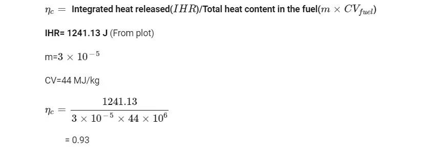
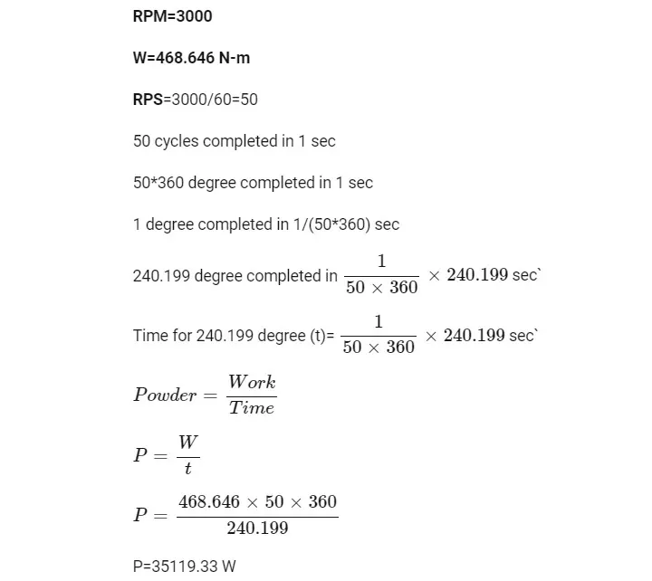
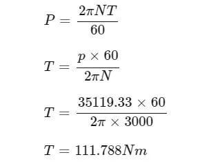
Q4. Determine the power and torque for this engine.
Power Calculation
Torque Calculation
Q5. What is the significance of ca10, ca50 and ca90?
A5.
Ca10 Means that 10% of the combustion takes placea the initial stages of the Simulation or the combustion process.
Ca50 means that 50% of the combustion has taken place. This basically means that 50% of the combustion takes place at half the combustion cycle.
Ca90 means 90% of the combustion has taken place. This means that 90% of the combustion takes place at the end of the combustion cycle.
The link for the video is
Velocity Animation for the Hydro simulation of a PFi gasoline Engine.
In the below animation we can see the temperature variation accros the strokes of the PFI Engine.
CONCLUTIONS AND RESULT
We have seen the running of a PFi engine on gasoline fuel. THrough this project we have tried to depict all the parameters that are required for a basic running of an engine at a certain RPM.
We have also concluded that while intake the gases form a swirl motion inside the combustion chamber. The chamber is designed in such a way so that the gases do not form acute or point combustion and the flame propogation is consistent throughout the power stroke. This help increasing the combustion efficiency of the engine and To decrease unwanted Tumble vortex inside the combustion chamber.