Week 10: Project 1 - FULL HYDRO case set up (PFI)
Title: Simulation of Full Hydro 4-Stroke PFI(Port fuel injection)
Objective: 1. To understand the entire case setup
2. Simulation of PFI Engine in paraview
3. To calculate the engine performance parameters value
Introduction
PFI Engine
Historically, the most widely produced internal combustion engines were of the Port Fuel Injected (PFI) design, where the fuel is sprayed into the intake ports to mix with incoming air. In fact, many new vehicles are still manufactured with this engine design. The fuel injectors in PFI configurations are typically mounted in the intake manifold and the air/fuel mixture is pulled into the cylinder head as the intake valve opens.
Theory: As in previous chaleenge PFI engine is run with No hydro simulation & checked the movement of piston, valve etc. This challenge is realted with the full hydro simulation of Port fuel injection engine. for that there is collect the data related with the engine , spark nozzle postion etc. this data is fill up in to case setup & run for crank angle degree & post procress the result. in this challenge its very important to find out the Compression ratio, combustion efficiency etc.
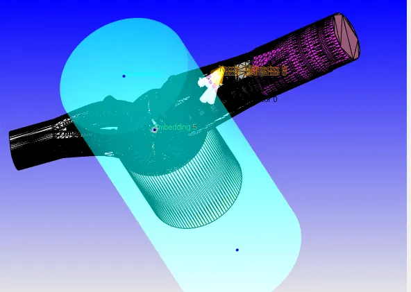
Given geometery
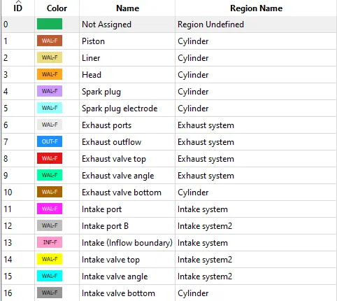
Boundry name created
Case setup:
1 Application type -Crank based IC Engine
Cylinder bore=0.0856m
Crank raduis=0.09
Connecting rod length=0.18
Crank speed=3000 rpm
2.Materials
Gas simulation>import them.dat file
Reaction mechanism> import mech.dat
Turn on >Parcel simulation
Parcel simulation
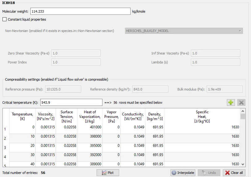
As we are simulating gasoline fuel in to the PFI engine. so, we need to select the relative parcel that will behave like gasoline fuel . so, there is consider IC8H18 (Iso-octane) liquid. here its very important to observe the various properties value & it should be nearly match with gasoline fuel
3. Simulation parameter
Solver> Transient
Temporal type> Crank based simulation
Simulation mode> Full-hydrodynamic
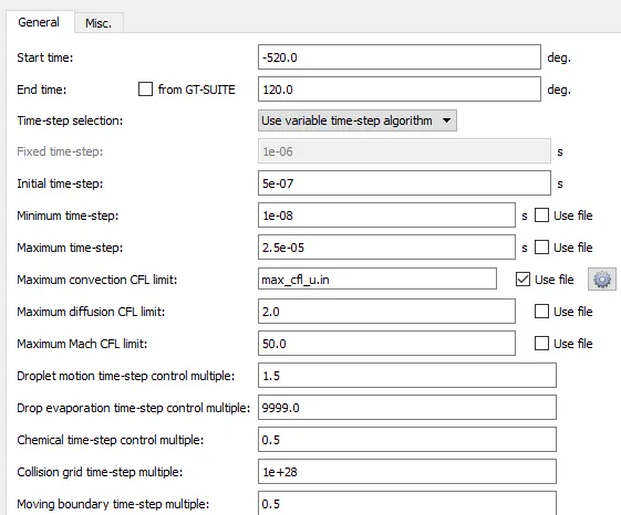
Simulation time parameter
Start time= -520 deg
End time= 120 deg
Intial time step=1e-7
Intial time step=5e-7 , maximum time step= 2.5e-5
4.Boundry condition
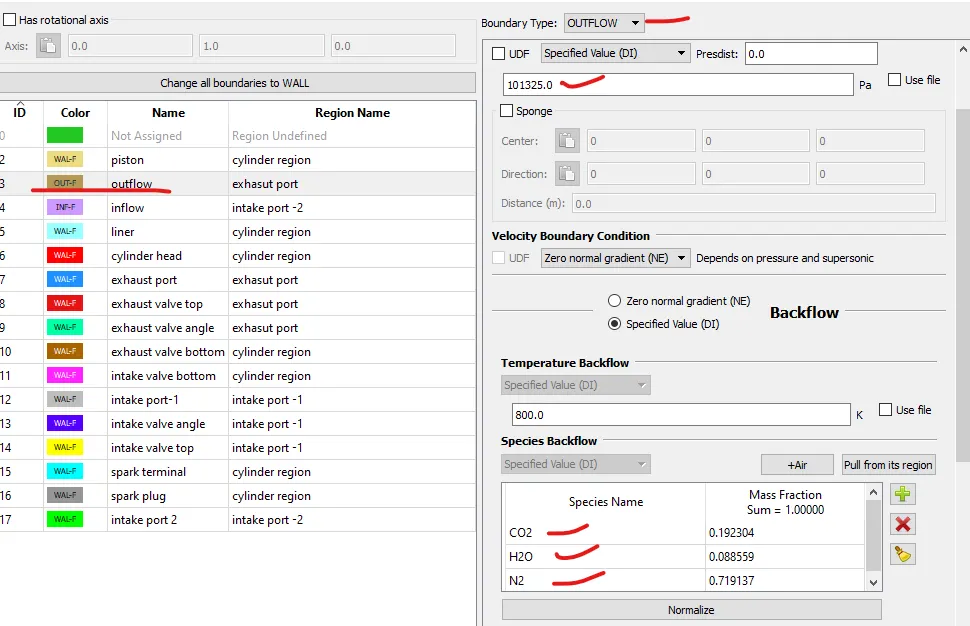
Outflow
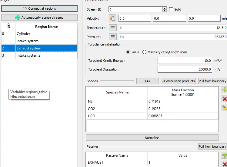
comnustion product is given CO2, N2, H20
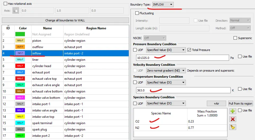
Inflow
at inflow air quantity is flow
Liner
Boundry type> Wall Surface movement> fixed
motion type>stationary Temp > 450k Turbulent tke> zero normal gradient
Cylinder head
Boundry type> Wall Surface movement> fixed
motion type>stationary Temp > 450k Turbulent tke> zero normal gradient
Exhaust port
Boundry type> Wall Surface movement> fixed
motion type>stationary Temp > 500k Turbulent tke> zero normal gradient
Exhaust valve top
Boundry type> Wall Surface movement>moving profile>exhaust lift.in
wall motion type>Translating Temp > 525k Turbulent tke> zero normal gradient
Exhaust valve angle
Boundry type> Wall Surface movement>moving profile>exhaust lift.in
wall motion type>Translating Temp > 525k Turbulent tke> zero normal gradient
Exhaust valve bottom
Boundry type> Wall Surface movement>moving profile>exhaust lift.in
wall motion type>Translating Temp > 525k Turbulent tke> zero normal gradient
Intake valve bottom
Boundry type> Wall Surface movement>moving profile>intake lift.in
wall motion type>Translating Temp > 480k Turbulent tke> zero normal gradient
Intake valve angle
Boundry type> Wall Surface movement>moving profile>intake lift.in
wall motion type>Translating Temp > 480k Turbulent tke> zero normal gradient
Intake valve top
Boundry type> Wall Surface movement>moving profile>intake lift.in
wall motion type>Translating Temp > 480k Turbulent tke> zero normal gradient
Spark terminal
Boundry type> Wall Surface movement>fixed
wall motion type>Stationary Temp > 600k Turbulent tke> zero normal gradient
Spark plug
Boundry type> Wall Surface movement>fixed
wall motion type>Stationary Temp > 550k Turbulent tke> zero normal gradient
Intake port-
Boundry type> Wall Surface movement>fixed
wall motion type>Stationary Temp > 425k Turbulent tke> zero normal gradient
Intake port-B
Boundry type> Wall Surface movement>fixed
wall motion type>Stationary Temp > 425k Turbulent tke> zero normal gradient
Intial condition & events
Region & Intialization
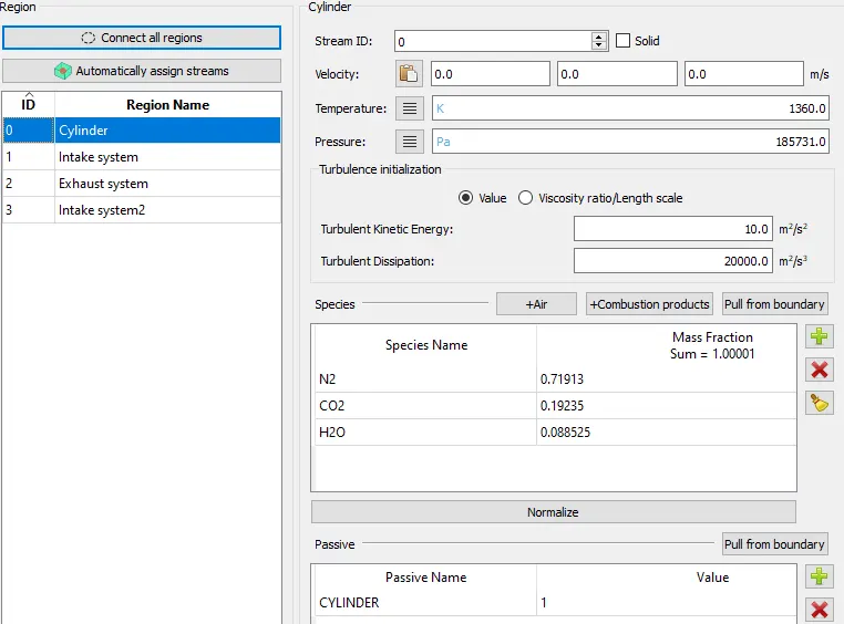
Cylinder
after combsution process species formed in three name CO2, H20, N2
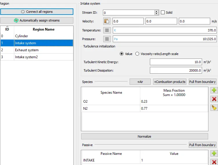
Intake system
at intake only air send it
Intake system 2
Fuel is injection through nozzel , so that there is use of parcel IC8H18 (Iso-octane)
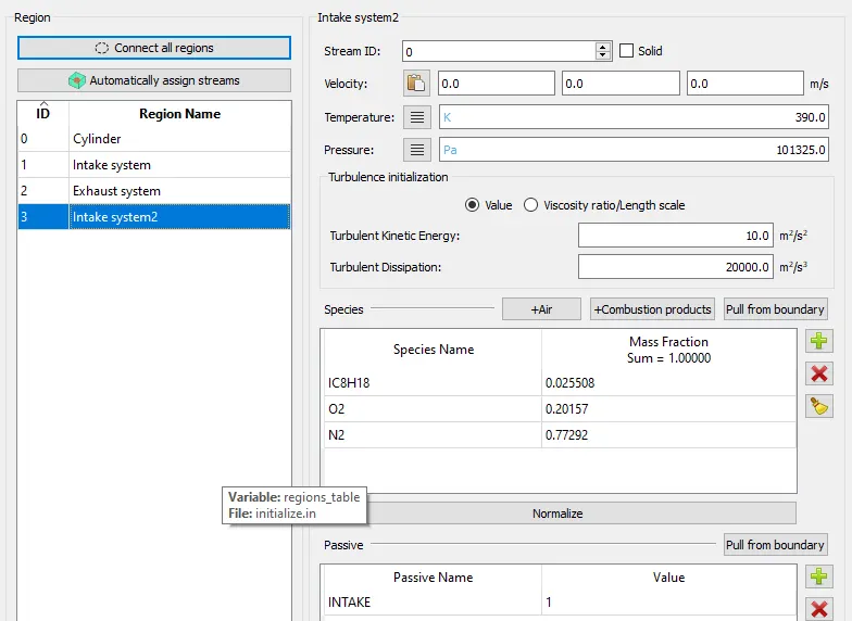
Exhaust system
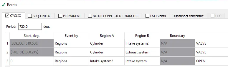
Event is created
for flow the fuel from intake system to cylinder region event is created, so that disconnected triangle is created & it will be broken so, that flow of fuel is start, its same for exhaust port after combustion process is over. For intake system2 & intake system event is open
Physical modeling
Spray modeling
By click on Physical modeling we can choose the spray modeling. spray modeling is nothing but the injecting the fuel in to intake port.
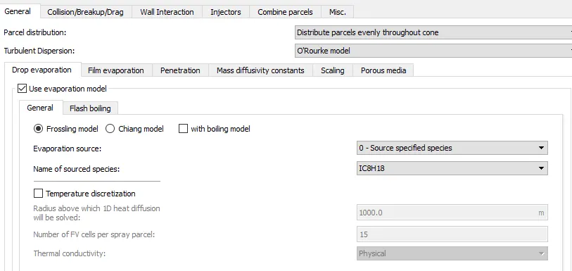
1. General: Parcel distribution evenly throughout the cone. this option is select for petrol fuel because of distribution of fuel evenly. so, that combustion process will be complete
2. Turbulent dispersion: O route model. this consider for maintain the turbulent effect. for petrol fuel typicall this option uses
3. Evporation model: its uses for conversion of fuel in to small diameters molecule
Evporation Source: 0-Source specified species. for conversion of liquid fuel in to the IC8H18 fuel
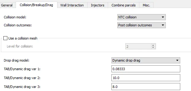
Collision breakup model
Colision model: NTC collision
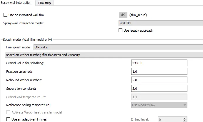
Wall interaction
its used for when fuel is hit to the wall film it will splash in to the combustion chamber by use of O route model
Injector
By use of injector fuel (Iso-octane) is injected in to the intake port

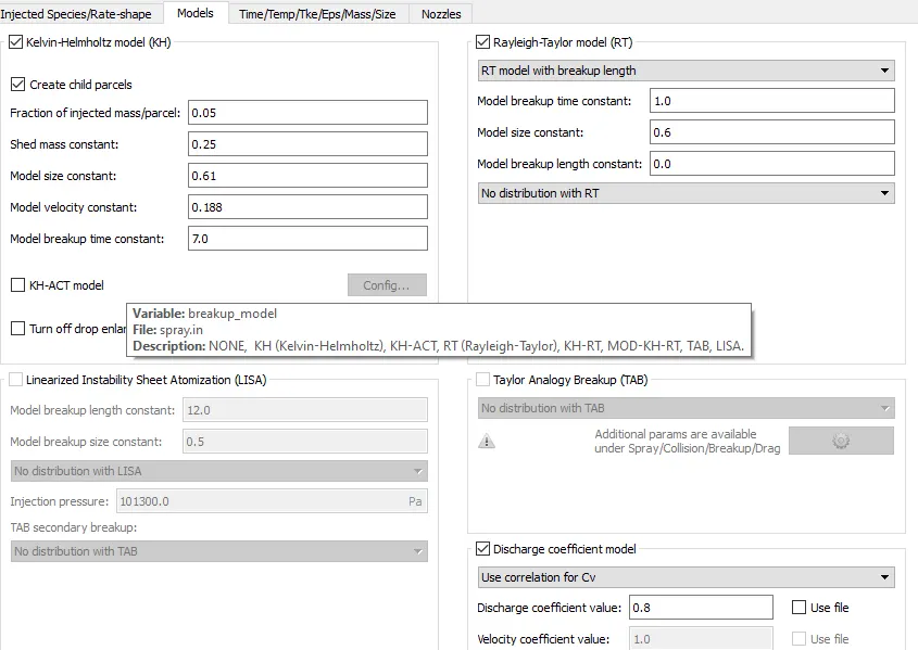
Models
Kelvin-helmhotz & rayliegh taylor model for spray the fuel in the form of cone shape. constant are provided for breakup the fuel.
Select the discharge coefficient is 0.8
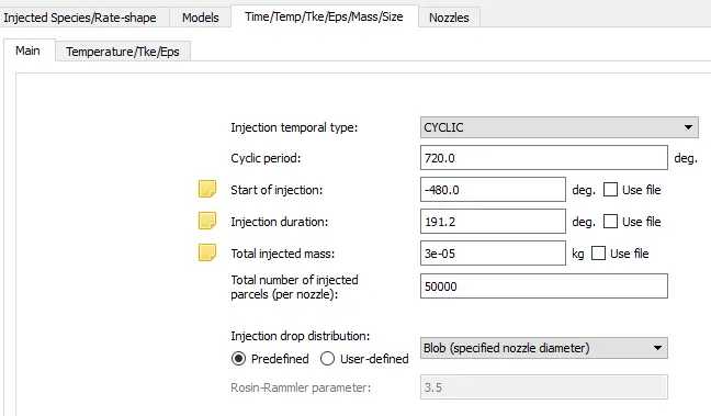
Time temp & size
total injected mass is 3e-5 kg for perticulat time for once in 720 degree
Injection type is cyclic
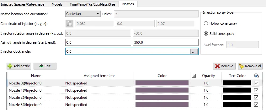
Nozzle location
nozzle location & orientation is cartesian
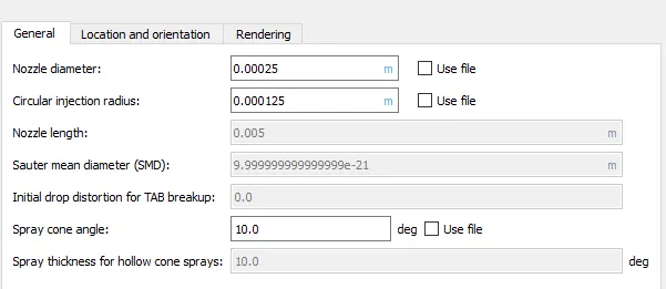
Nozzle specification
Nozzle diameter=0.00025m Injection radius=.000125m
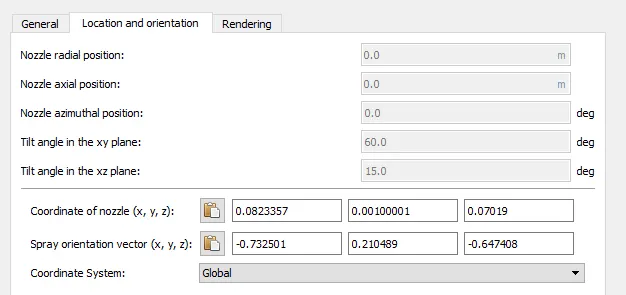
Location of Nozzel is set
coordinate & spray orientation location has been set
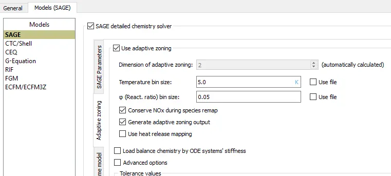
Combustion modeling
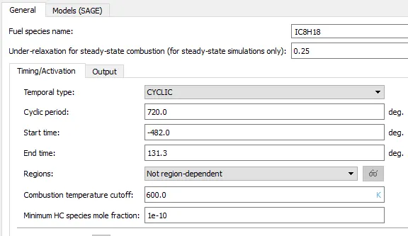
Consider the SAGE combustion model
General of combustion
Combustion is cyclic for every 720 degree
Start time of combustion -482 degree
end time of combustion 131.3 degree(at exhaust valve opening)
Souce & sink modeling
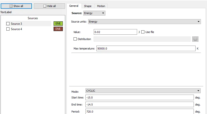
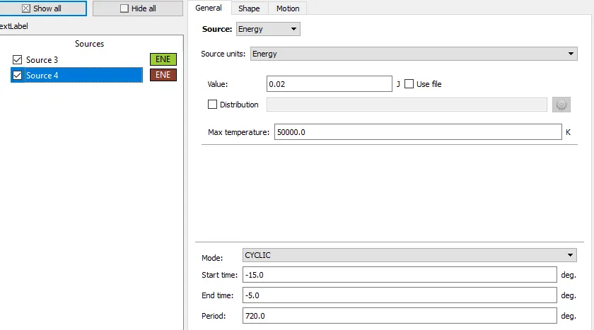
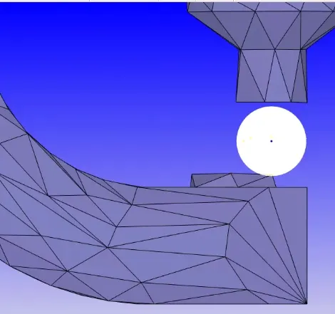
Basically there is provided two spark plug which is heat source & there is provided energy equation. value for heat source is provided 20 MJ. sink is fuel having temp. is increases by energy equation.
spark is start at -15degree
end time -14.5degree
Source 1
Source 2
Heat source location
Grid control
base grid size=.004m
Fixed embedding
Embeeding 1: Cylinder > Permanent
Fixed embedding= (base grid size)/2^n
base grid size uses =0.004m
n=2= scale
fixed embedding= 0.004/2^2
= 0.001 m
Embeeding 2: Boundry > Intke valve angle
Fixed embedding= (base grid size)/2^n
base grid size uses =0.004m
n=3= scale
embedd layer=2
fixed embedding= 0.004/2^3
= 0.0005 m
Embeeding 3: Boundry > Exhaust valve angle
Fixed embedding= (base grid size)/2^n
base grid size uses =0.004m
n=2= scale
embedd layer=2
fixed embedding= 0.004/2^2
= 0.001 m
Embeeding 6: INJECTOR > cyclic
Fixed embedding= (base grid size)/2^n
base grid size uses =0.004m
n=4= scale
start time=-485 degree, end time =-265 period= 720 degree
fixed embedding= 0.004/2^4
= 0.00025 m
Adaptive mesh refinment
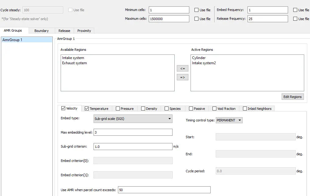
Adaptive mesh refinment based upon the velocity & temprature
Sub grid criteria for velocity is based on 1m/s velocity .Velocity timing control is permanent
Sub grid criteria for Temprature is based on 2.5k.Temp timing control is Cyclic for 720 degree. Temp AMR start at -17 deg & end at 131 deg
Embedd level is 3 for both refinment
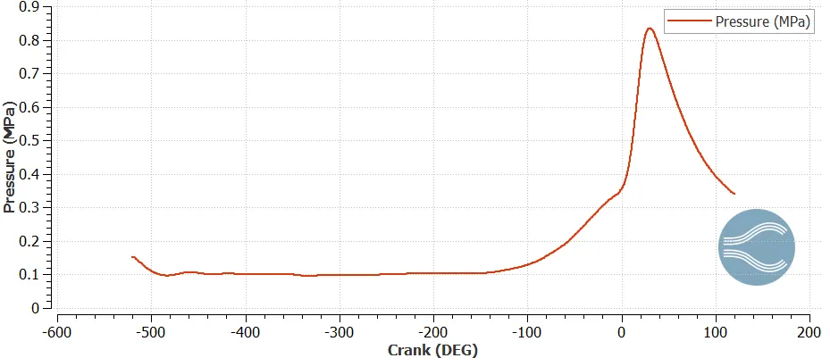
Result
1.Pressure plot
its shows accurate pressure plot as compression pressure is increases & high at combustion start
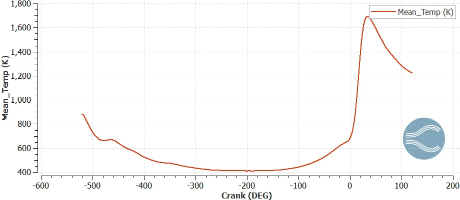
Mean temp
High temp occurs at the start of combustion process
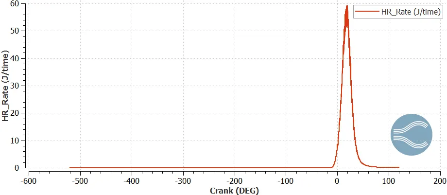
Heat rate
High heat rate occurs at the start of combustion process
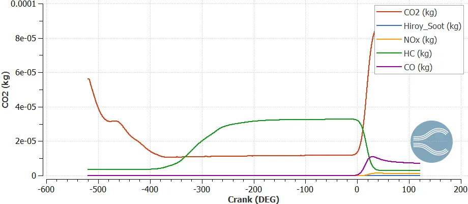
Emission
Higher HC emission at the start of combustion process
Compression ratio of engine
compression ratio can calculate by volume graph
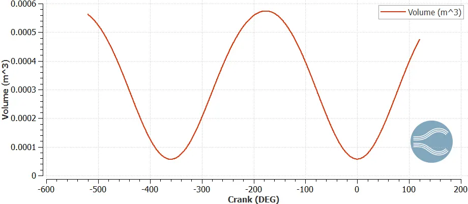
Compression ration = Maximum volume/ minimum volume
= 5.7 *e-4/5.7 *e-5
=1e-9 *1e10
=10:1
Combustion efficiency
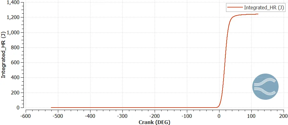
Combustion efficeincy tell us how much amount of heat is developed & its utlization for burning of fuel. combustion efficency tell us how perfectly combustion process take place. higher combustion efficiency higher power production & lesser emission
Combustion efficiency = Total heat released by combustion/ total heat content available in fuel
Total heat content of fuel= amount of fuel*calorific value
=3e-5 kg/cycle * 44*e6 J/kg
=1320J
COMBUSTION EFFICENCY= 1241/1320
=94%
Power & Torque of Engine
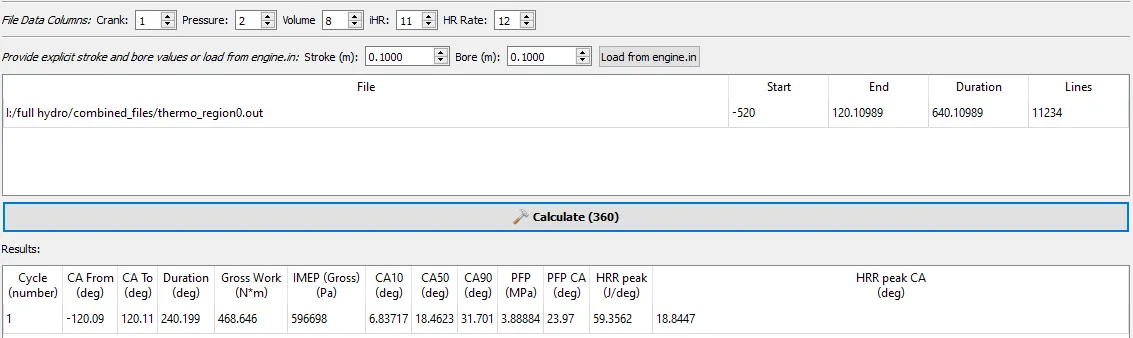
From the engine performance calculator we got the workdone 468.646 N-m for the process
Rpm =3000 RPS= 50 DPS(Degree per second)=3000 *6=18000
Time per degree=60/ 360*RPM
=5.55*e-5
Time per 720 degree=0.04
time per 240.199degree=0.01334sec per cycle
POWER= 468.646/0.01344
=35.13KW
Power =2piNT/60
=111.8N-m
What is Ca10, Ca50, Ca90
Ca10 = 10% of the combustion take place. so, 10% combustion will take place at intial stages of combustion process
Ca50 = 50% of the combustion take place. so, 50% combustion process will take place at half of combustion process.
Ca50 = 90% of the combustion take place. so, 90% combustion process will take place at the end of combustion process.
What is need of wall heat transfer model
heat transfer is important factor that affect on the performance, emission of engine. in CFD simulation we generally uses near wall measurment under CFD simulation. but there is some heat losses occurs its due to temprature gradient across wall, therfore here to reduce heat losses combustion heat transfer model. in the CFD simulation for capture heat transfer assumption are made , but its correct. so, by the wall heat transfer model we accurately predict the heat transfer.
Animation of Full hydro Simulation
Overall conclusion
1.Calculate the compression ratio by volume
2.Calculate the Combustion efficiency intergrate heat rate
3. Calculation of POER & TORQUE
4. importace of wall heat transfer model