Week 10: Project 1 - FULL HYDRO case set up (PFI)
Week 10 Project
FULL HYDRO case set up (PFI)
Objective: To simulate the Full-hydro case setup of PFI.
- What is the compression ratio of the engine?
- Calculate the Combustion efficiency of the Engine.
- Determine the Power and torque of the engine by using an engine performance calculator.
- What is the significance of CA10, CA50, and CA90?
- Why do we need a wall heat transfer model? Why can't we predict wall temperature from CFD simulation?
A petrol engine, also known as a gasoline engine, is an internal combustion engine in which the air-fuel mixture is ignited due to the spark provided by a spark plug. Therefore, it is also known as a SI engine. It uses petrol as its fuel source.
In 1876, Nikolaus August Otto designed the first petrol engine. A petrol engine works on the basic principle of the Otto cycle
The spark plug of the engine takes electric current from the vehicle battery to generate a spark. This spark plug is usually located on the combustion chamber’s top for a quick ignition of the air-fuel mixture.
The ignition process of the fuel produces heat, which is transformed into mechanical work in the power stroke of the piston.
In the old version of the SI engines, air and fuel (petrol or gasoline) are mixed before sending them into the combustion chamber for compression and ignition. While the latest SI engines use a fuel injector that injects fuel directly into the combustion chamber, the mixing process occurs there. This mixing process is regulated electronically by a fuel injector.
The petrol engines have high auto-ignition temperatures. Therefore, a petrol engine has a low compression ratio than a diesel engine.
The compression ratio of a petrol engine is usually 6:10. The gasoline engines can also run on fuels other than petrol like natural gas (CNG), methanol, Autogas (LPG), compressed hydrogen, ethanol, nitromethane (in drag racing), and bioethanol.
Petrol engines are most commonly used in different vehicles, including cars, motorcycles, boats, and airplanes. However, they have poor fuel efficiency and higher emissions than diesel engines and electric motors.
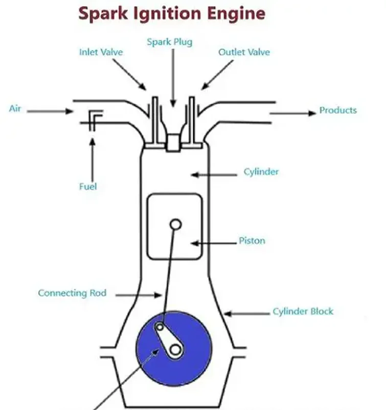
Petrol Engine Working Principle
The spark ignition (SI) engine working principle is similar to the compression (CI) engine, but there is little difference. In a diesel or CI Engine the ignition process happens due to high compression of the air-fuel mixture, while ignition occurs due to a spark in a petrol engine.
A petrol engine works according to the Otto cycle. A petrol engine works in the following way:
- Suction stage
- Compression stage
- Power stage
- Exhaust stage
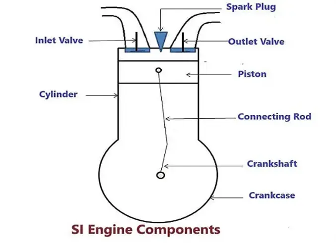
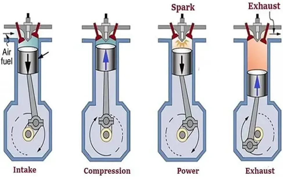
1) Intake or Suction Stroke
- For the intake stroke, the piston moves downward. As it moves down, a vacuum creates inside the combustion chamber; due to that, the air-fuel mixture starts coming from outside into the combustion chamber.
- In this stroke, the suction valve opens, and the exhaust valve remains closed.
2) Compression Stroke
- When the suction process of the air-fuel mixture completes according to the requirements, the piston travels upwards for the air-fuel mixture compression.
- As the piston moves up, it pressurizes the mixture into the combustion chamber. During this stroke, the intake valve and exhaust valve are closed.
- Due to the compression process, the temperature and pressure of the air-fuel mixture become very high.
- At the end of the compression process, a spark plug fires a spark and ignites the air-fuel mixture.
- Due to the provided spark, the combustion process of the air-fuel mixture occurs inside the combustion chamber. Due to this combustion, the piston further moves up, which further increases the temperature and pressure of the mixture. During this process, heat is produced.
3) Expansion Stroke
- The expansion stroke is also known as a power stroke.
- In this stage, the generated heat in the previous stroke (compression process) forces the piston to move downward (TDC to BCD) and turns the crankshaft.
- Due to the piston’s downward motion, the air-fuel mixture expands inside the chamber, and the pressure of the mixture decreases.
4) Exhaust Stroke
- In this stroke, the piston moves upward, opens the exhaust valve, and releases useless gases from the combustion chamber.
- After completing the exhaust stroke, the piston again moves down, and all four strokes repeat.
Gien parameters:
Engine Geometric Parameters
- Bore =0.086 m
- Stroke = 0.09 m
- Connecting rod length = 0.18 m
- RPM = 3000
Run parameters
- Simulation mode: No Hydro
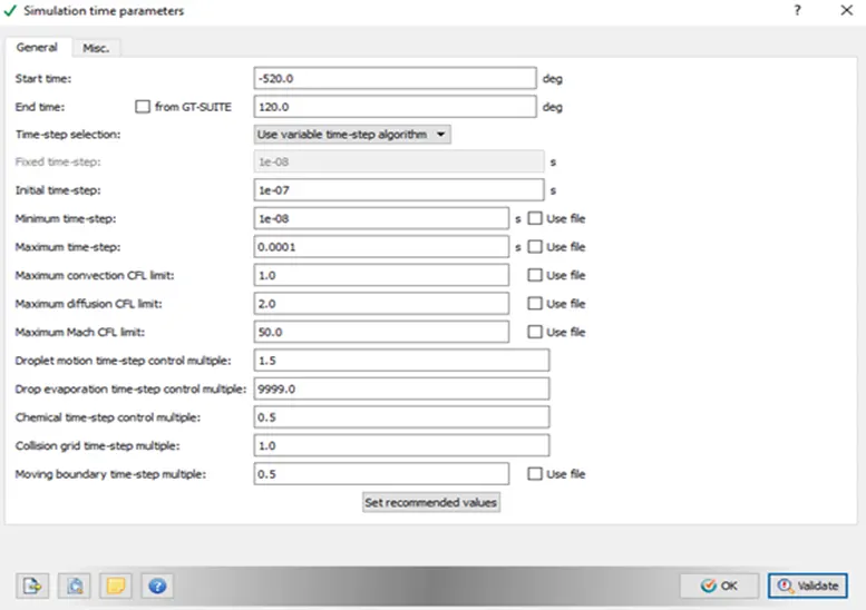
Simulation time parameters
- Start time: -520 deg
- end time: 120 deg
Boundary conditions
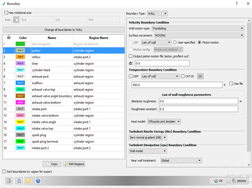
- Piston temperature - 450K
- Liner temperature - 450K
- Head temperature - 450K
- Spark Plug temperature - 550K
- Spark Plug electrode temperature - 600K
- Exhaust ports temperature - 500K
- Exhaust outflow - 1 bar
- Exhaust outflow temperature - 800k
- Exhaust species concentration - Calculate the stoichiometric condition
- Exhaust valve top temperature - 525K
- Exhaust valve angle temperature - 525K
- Exhaust valve bottom temperature - 525K
- Intake port - 1 temperature 425K
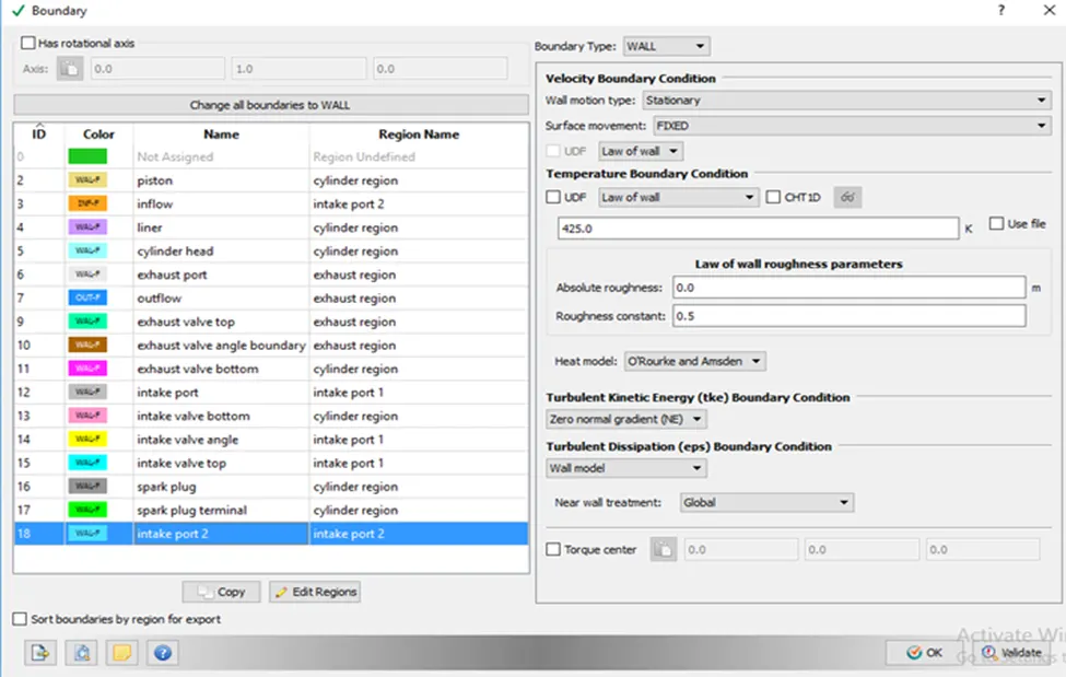
- Intake port - 2 temperature 425K
- Inflow pressure - 1 bar total pressure
- Inflow temperature - 363K
- Inflow species - Air
- Intake valve top temperature - 480K
- Intake valve angle temperature - 480K
- Intake valve bottom temeprature - 480K
Initial conditions
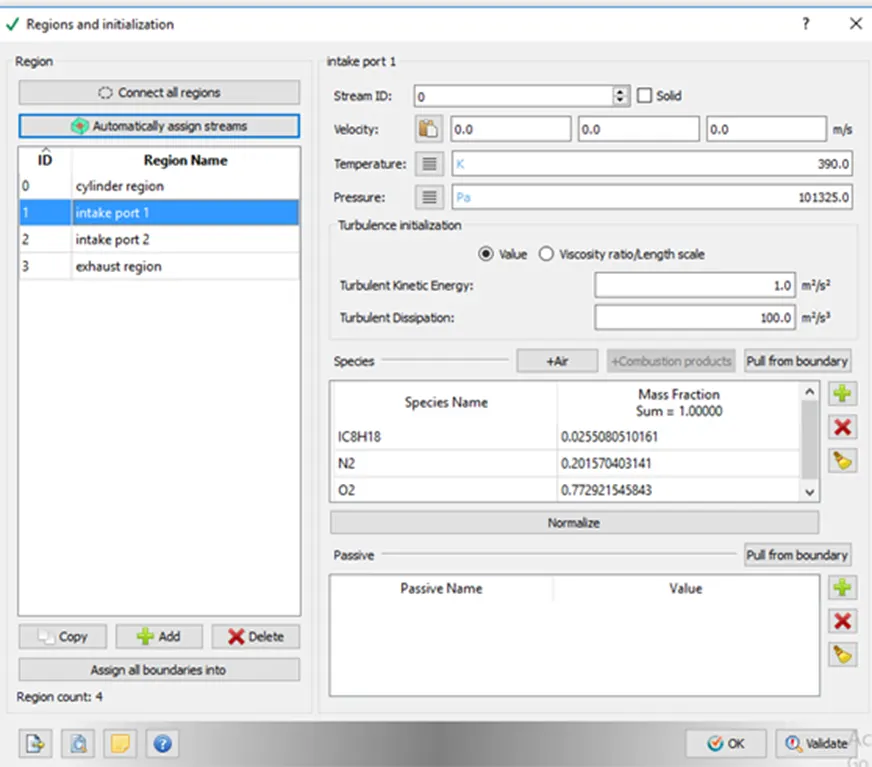
- Intake port - 1 (closer to combustion chamber)
- ic8h18 - 0.025508
- o2 - 0.20157
- n2 - 0.77292
- Temperature - 390k
- pressure - 1 bar
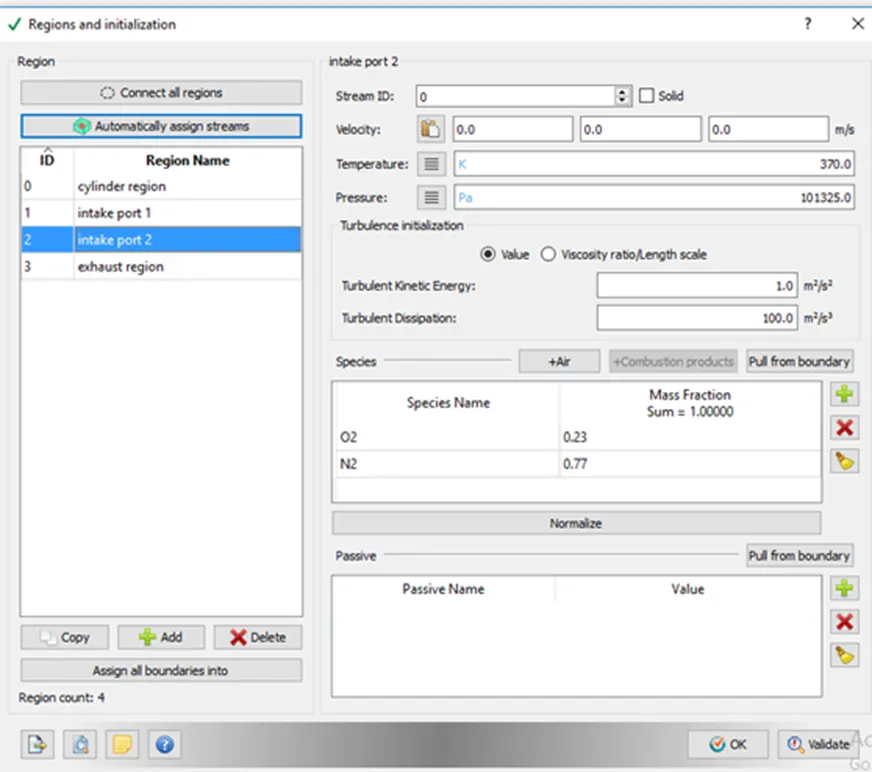
- Intake port - 2 (away from combustion chamber)
- Air
- Temperature - 370K
- Pressure - 1 bar
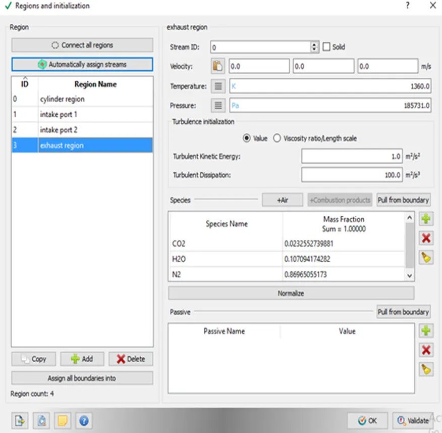
- Cylinder
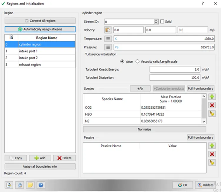
- Pressure - 1.85731 bar
- Temperature - 1360K
- Stoichiometric composition
Injection Parameters
- Fuel flow rate = 7.5e-4 Kg/second
- Injection start time = -480.0
- Injection duration = 191.2
- Fuel temperature = 330K
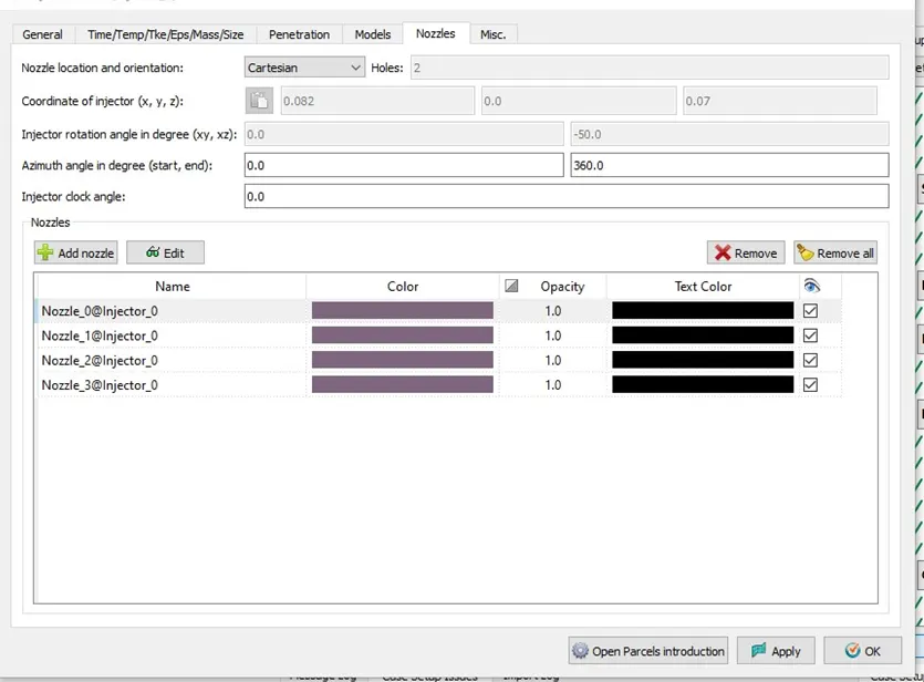
Nozzle positions
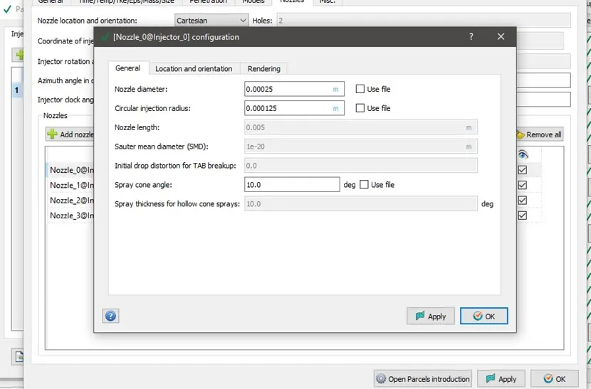
Nozzle diameter = 250 micrometer
Circular injection radius = Nozzle radius
Spray cone angle = 10
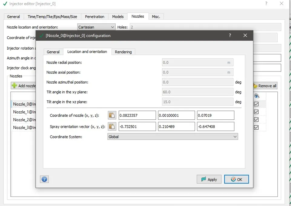
- Nozzle 0
- center 0.0823357 0.00100001 0.07019
- Align Vector -0.732501 0.210489 -0.647408
- Nozzle 1
- center 0.0823357 -0.00099999 0.07019
- Align Vector -0.732501 -0.210489 -0.647408
- Nozzle 2
- center 0.0823357 -0.0004 0.07019
- Align Vector -0.5 -0.2 -0.647408
- Nozzle 3
- center 0.0823357 0.0003 0.07019
- Align Vector -0.5 0.2 -0.647408
Spark Ignition Parameters
- Start of spark = -15 deg
- Spark duration = 10 deg
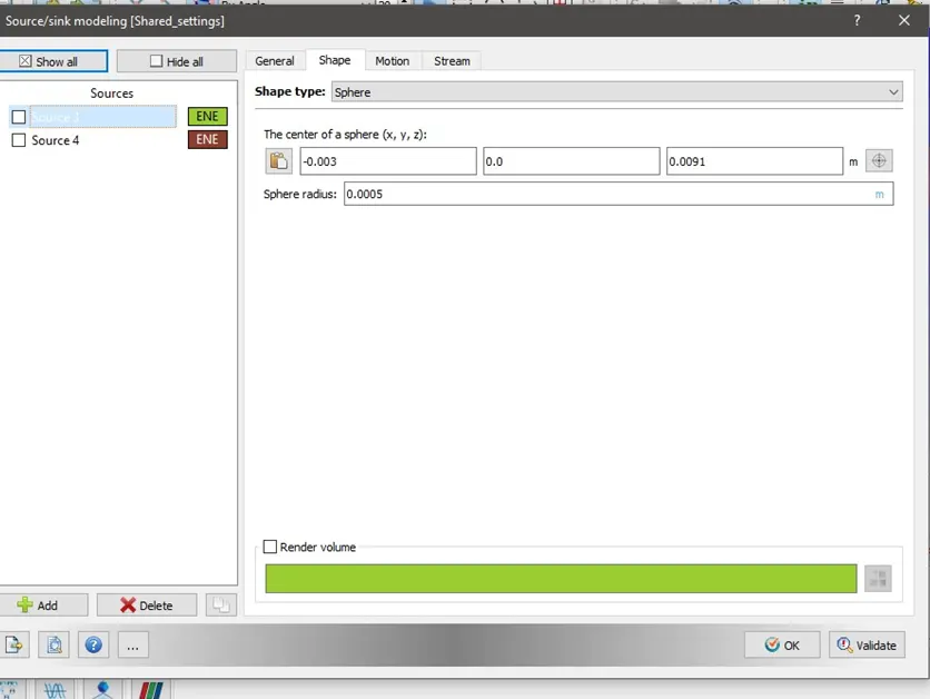
- Spark location = -0.003 0 0.0091
- Spark radius = 0.0005m
Geometry:
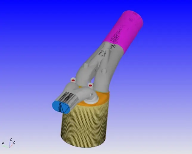
Simulation Case setup:
Application type:
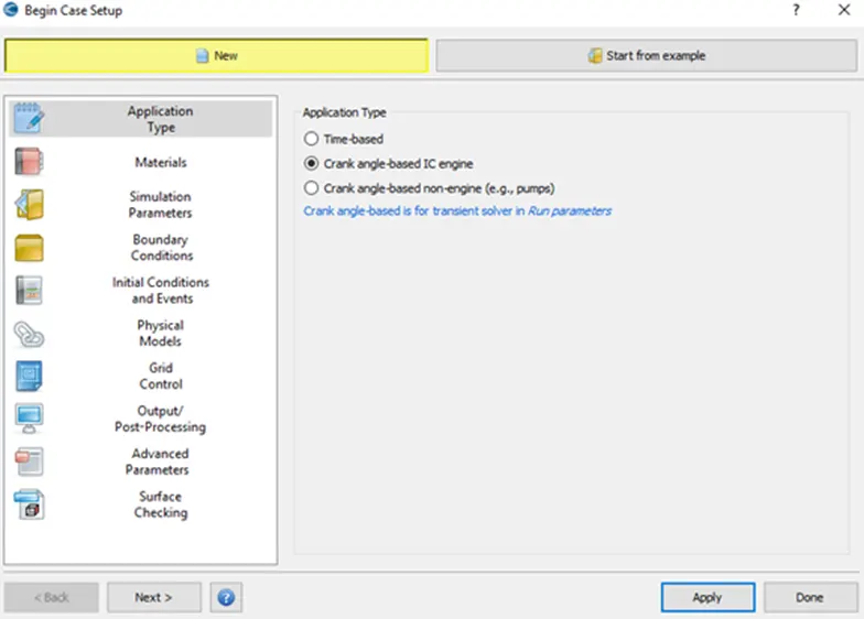
- Crank angle based
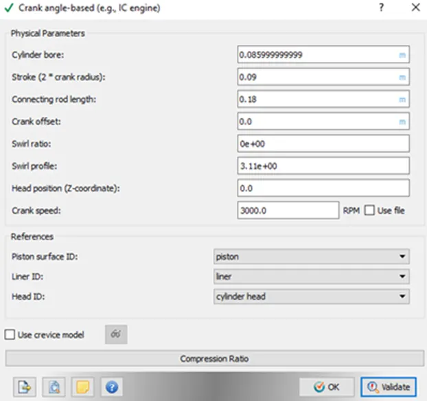
Materials:
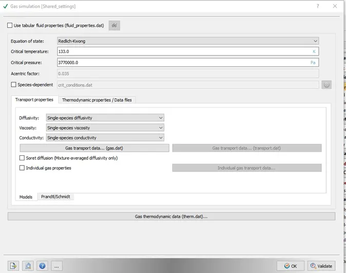
- Gas Simulation
- We select Parcel Simulation
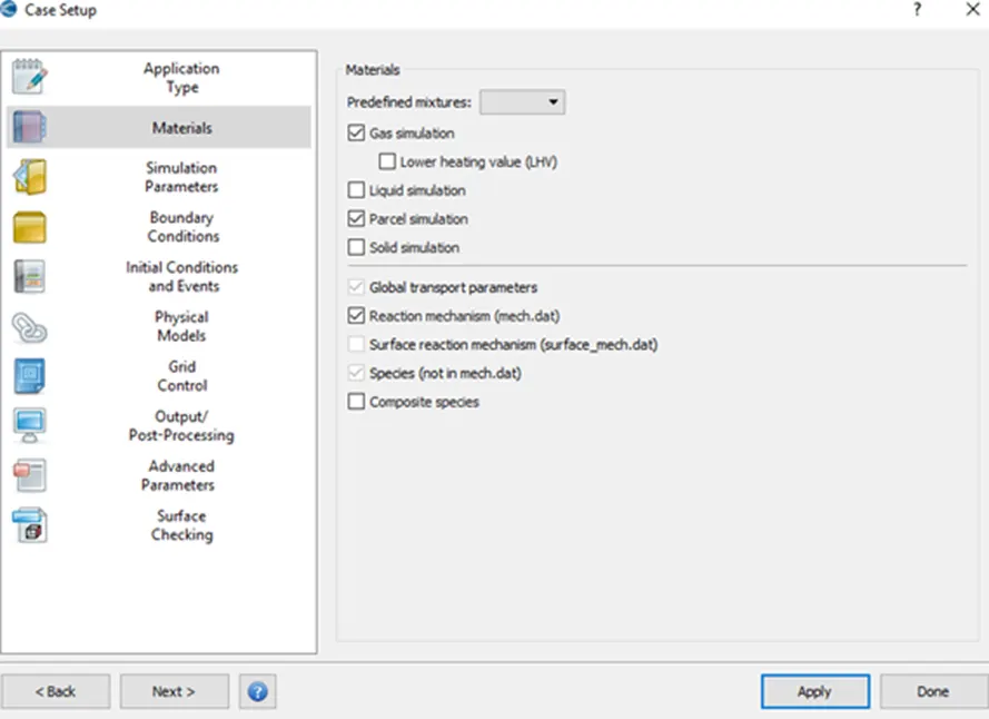
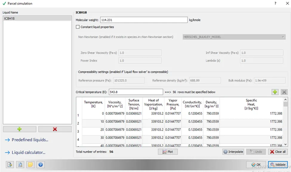
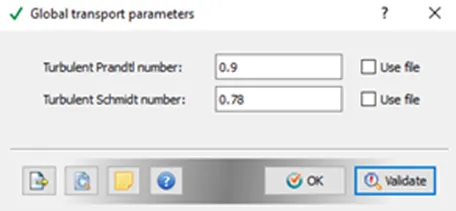
- Global Transport Parameters
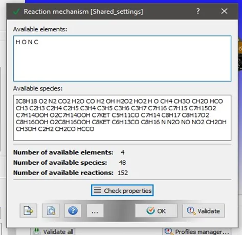
- Reaction Mechanism
therm.dat and mech.dat values loaded into the profile.
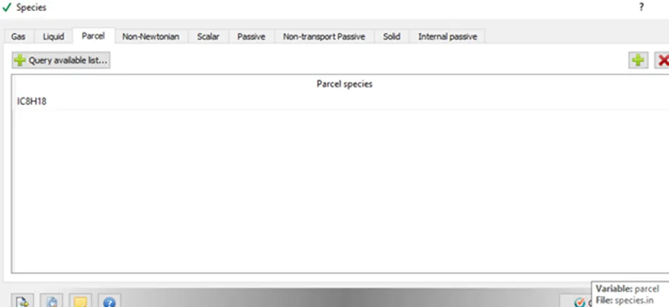
- Species
Simulation Parameters:
- Run Parameters
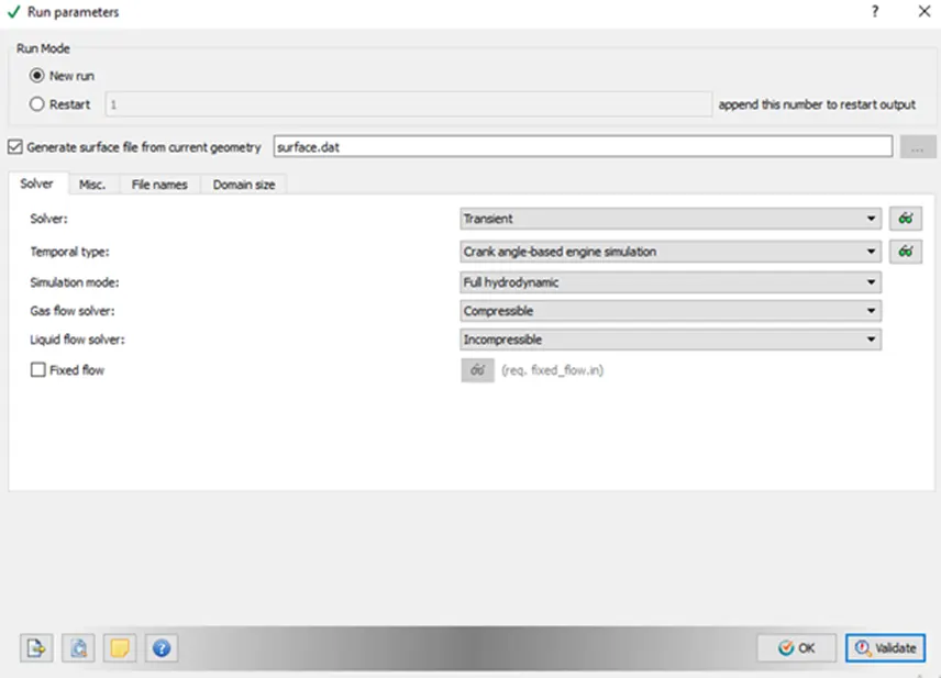
- Simulation time Parameters
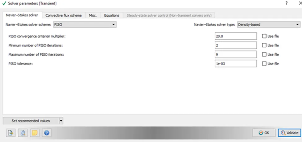
- Solver Parameters
Regions and initialization
A region is a collection of boundaries used to differentiate different areas in the boundary.
- Cylinder region
- Intake Port 1
- Intake Port 2
- Exhaust region
Boundary Conditions:
- Piston
- Inflow
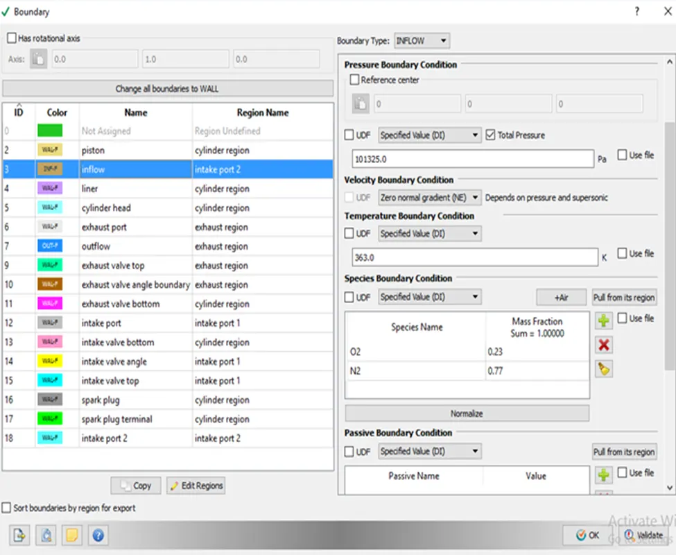
- Liner
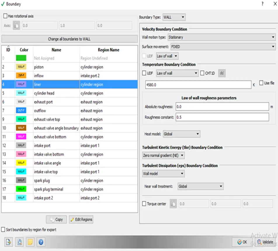
- Cylinder Head
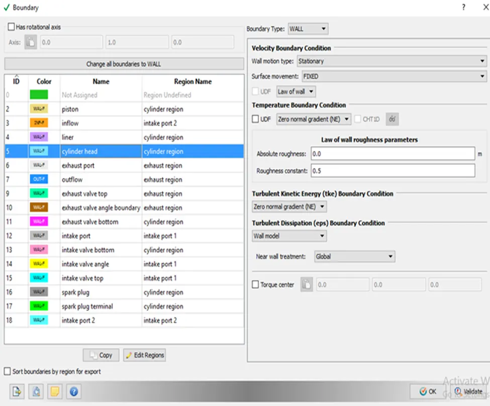
- Exhaust Port
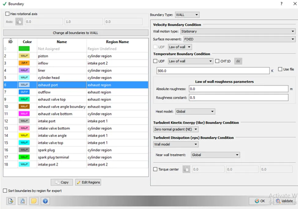
- Outflow
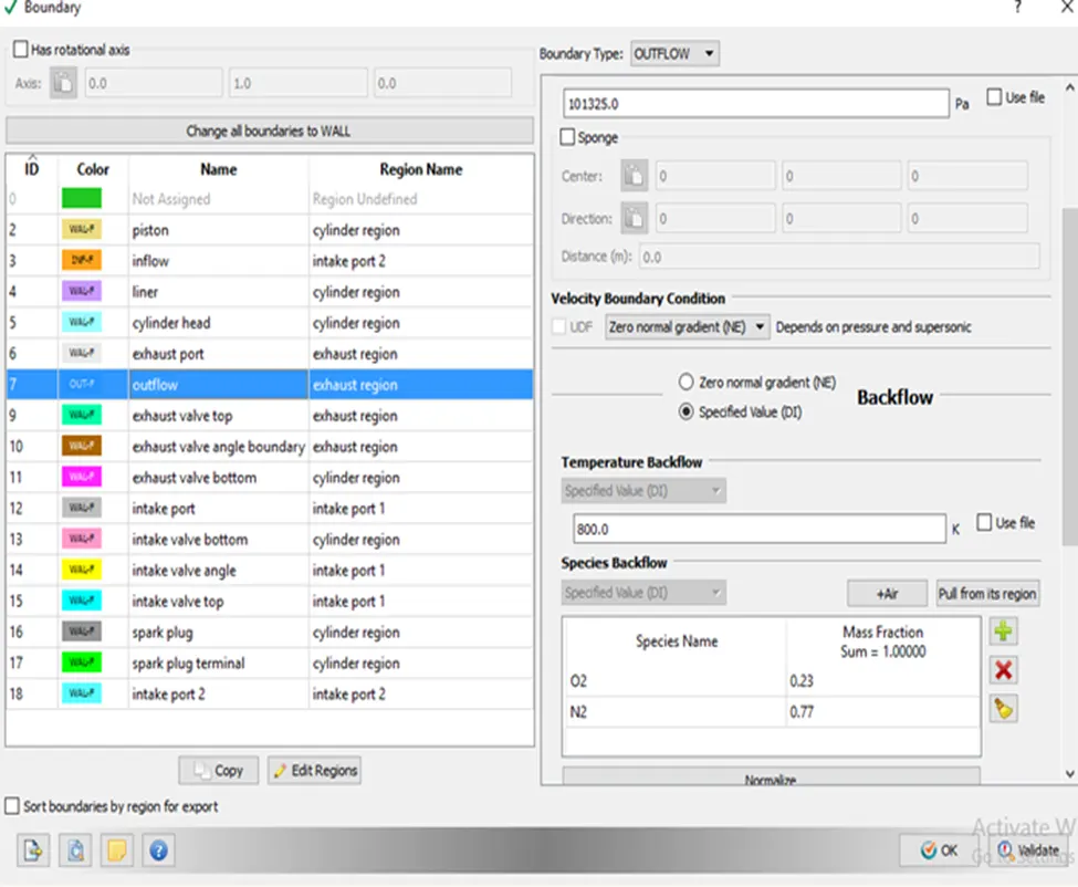
- Exhaust Valve Top
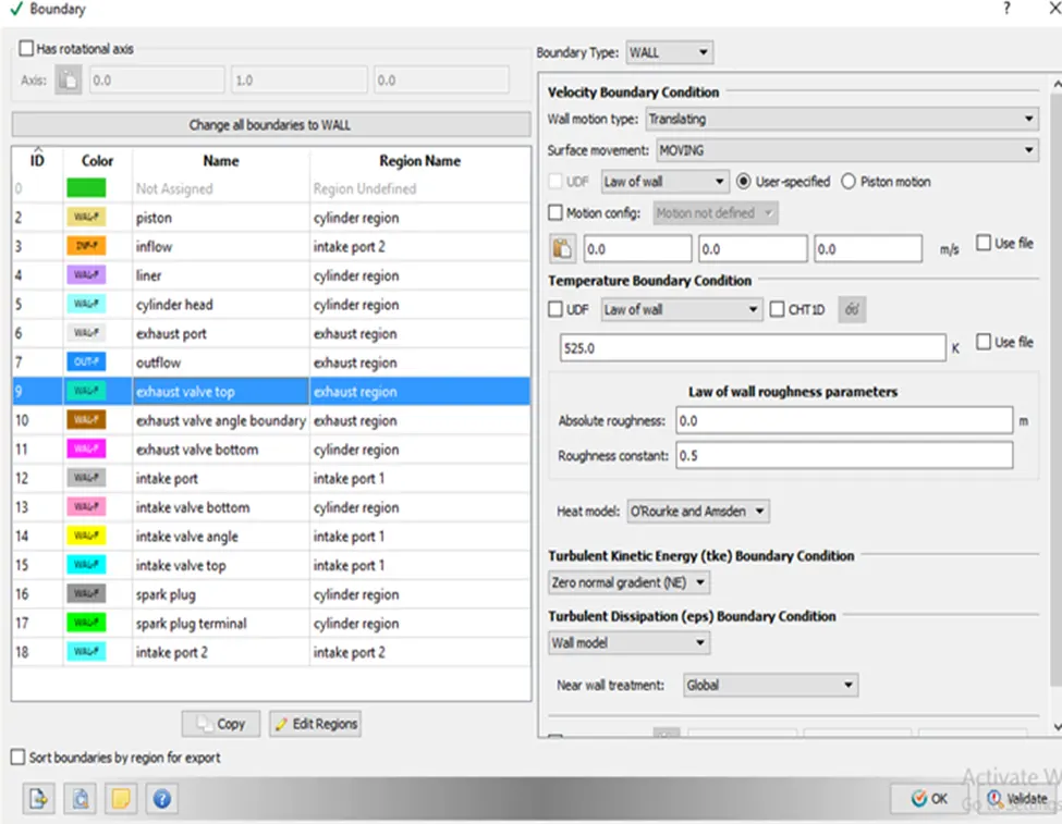
- Exhaust valve angle boundary
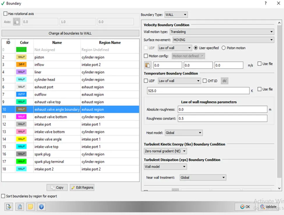
- Exhaust Valve Bottom
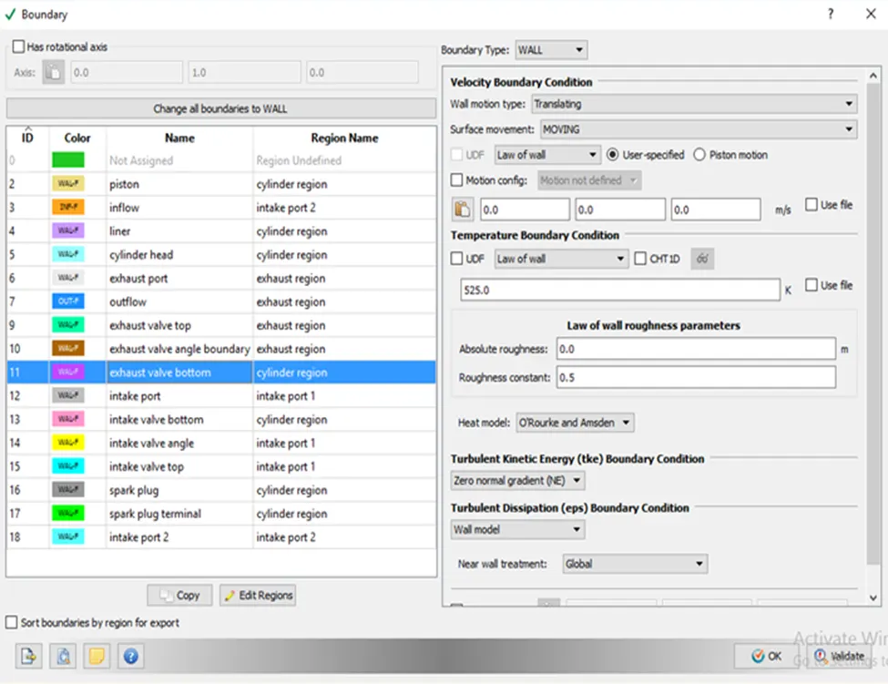
- Intake Port
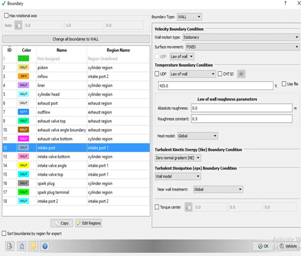
- Intake valve bottom
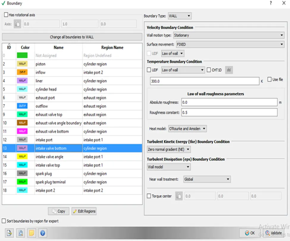
- Intake valve angle
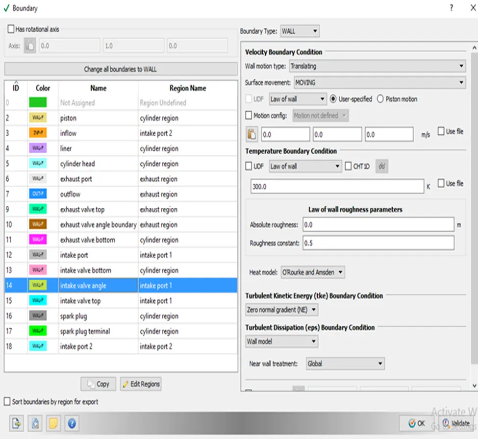
- Intake valve top
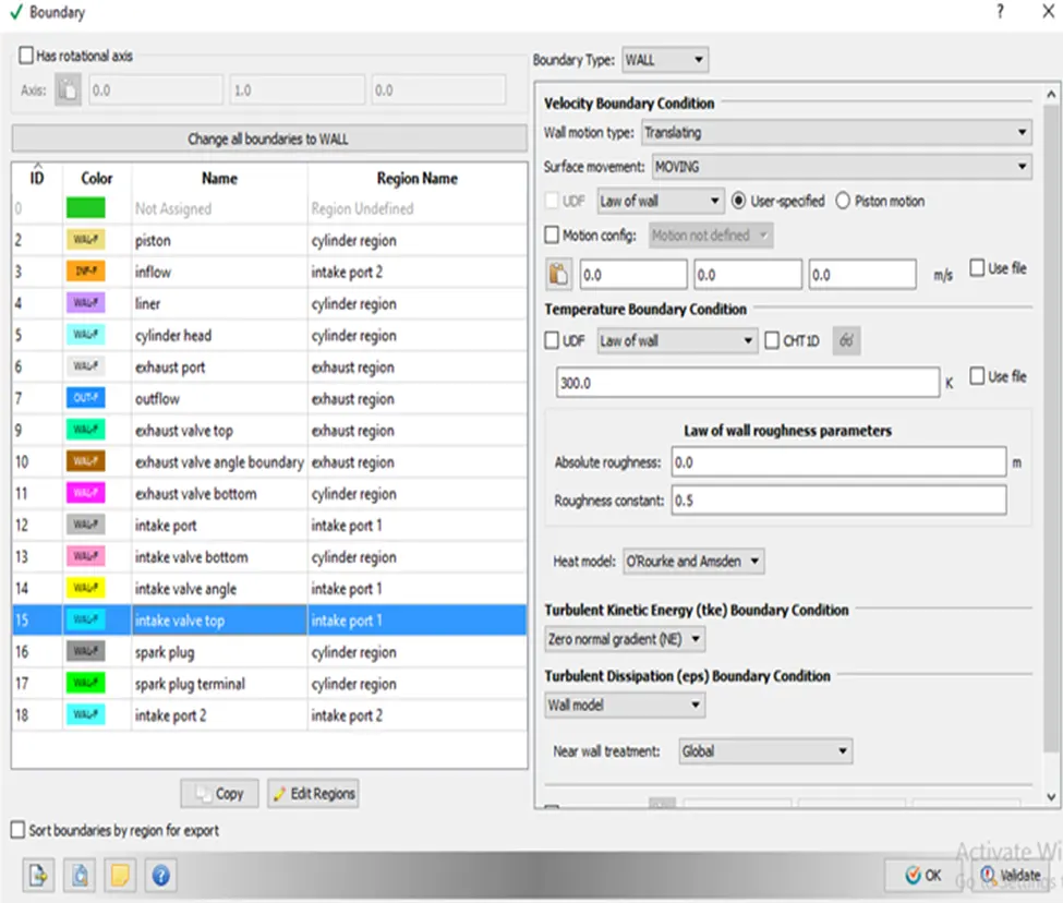
- Spark plug
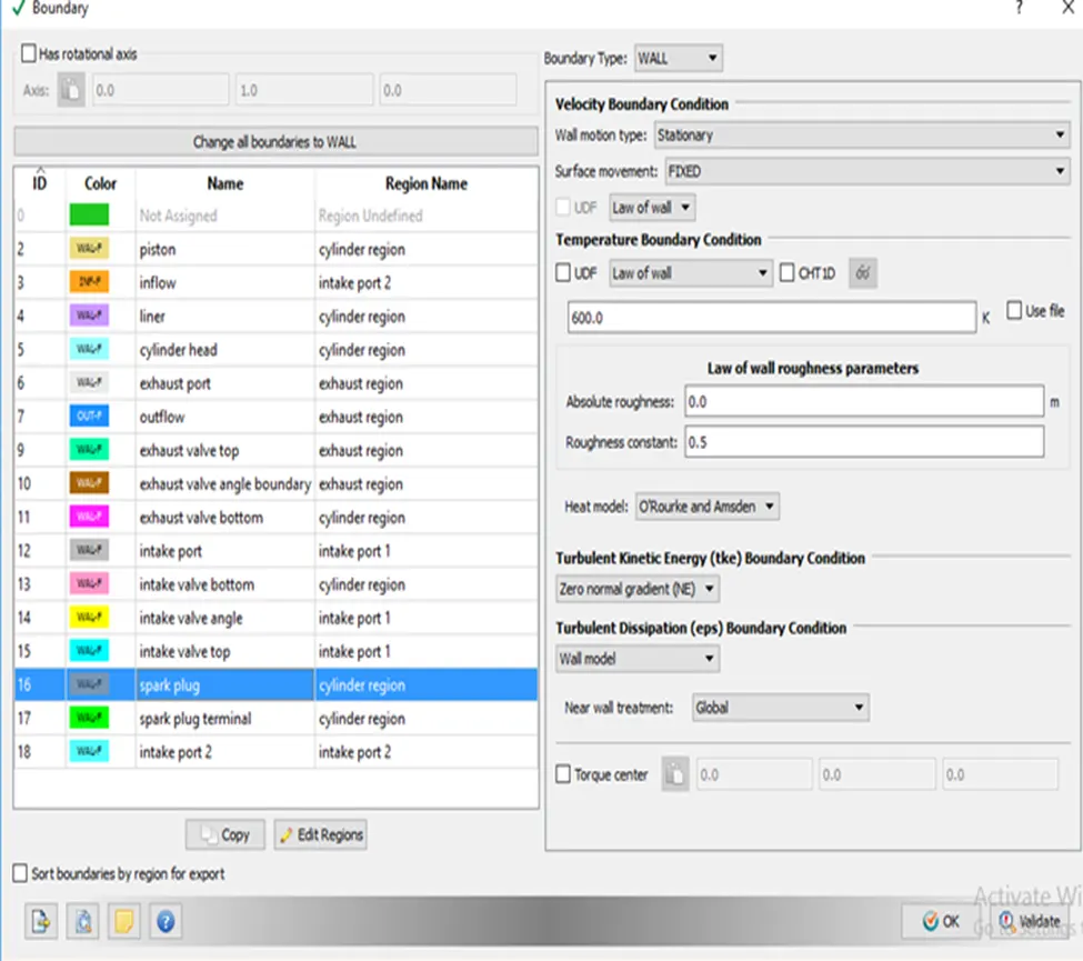
- Spark plug terminal
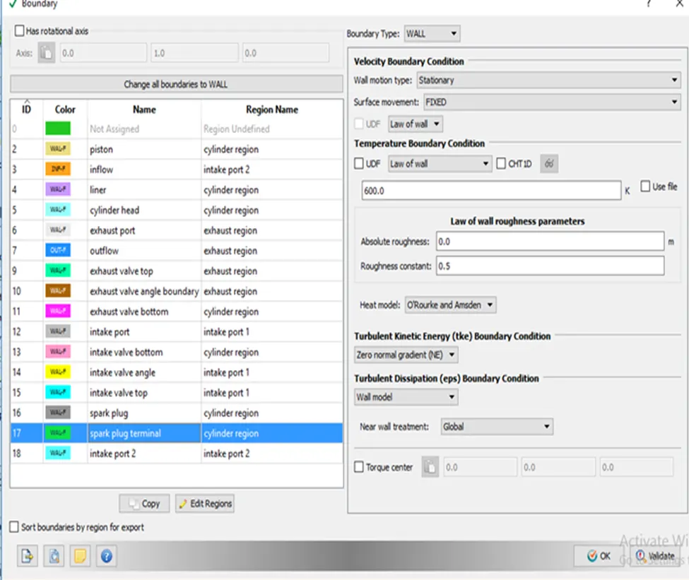
- Intake port 2
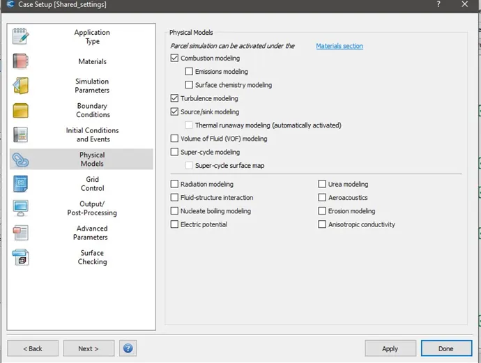
Physical Models:
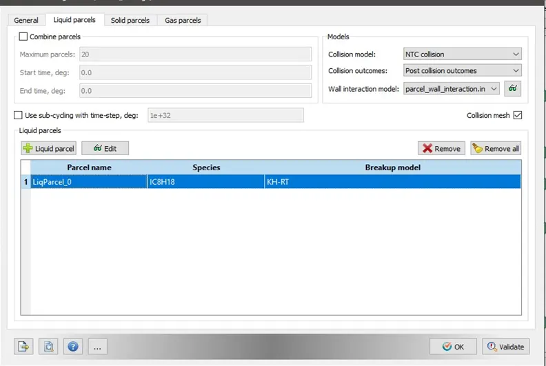
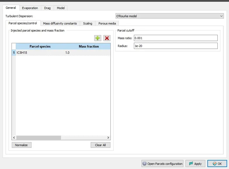
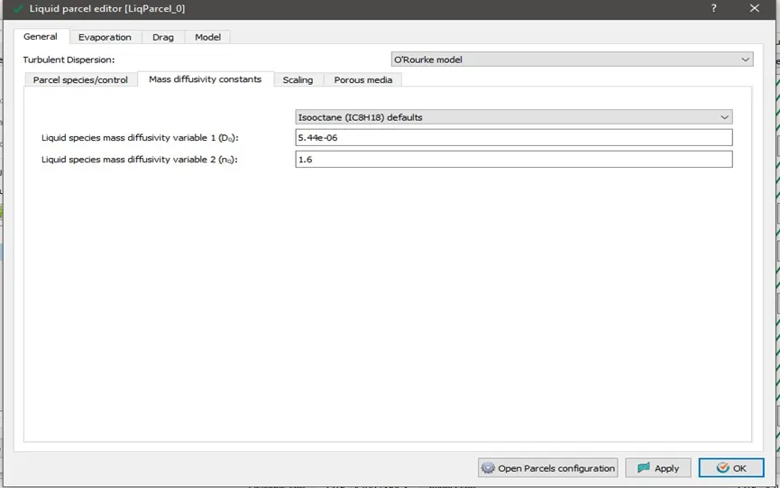
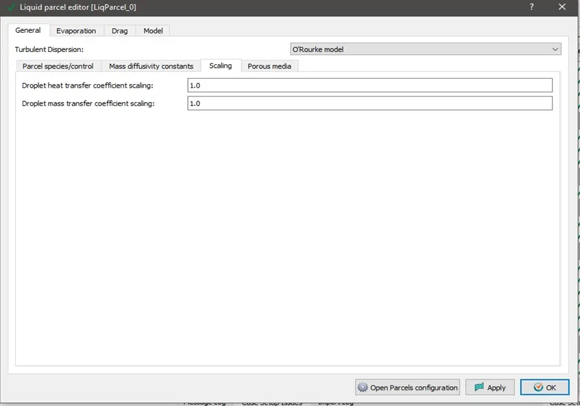
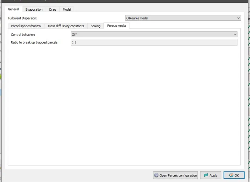
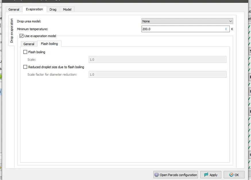
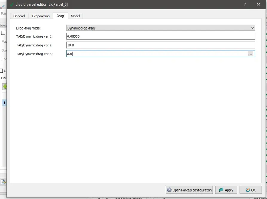
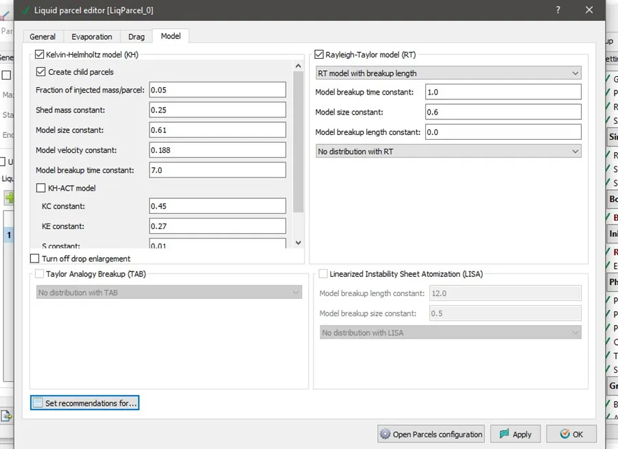
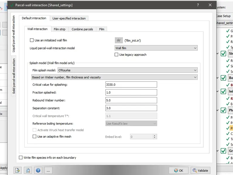
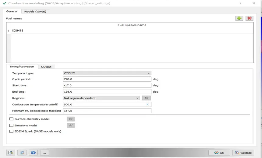
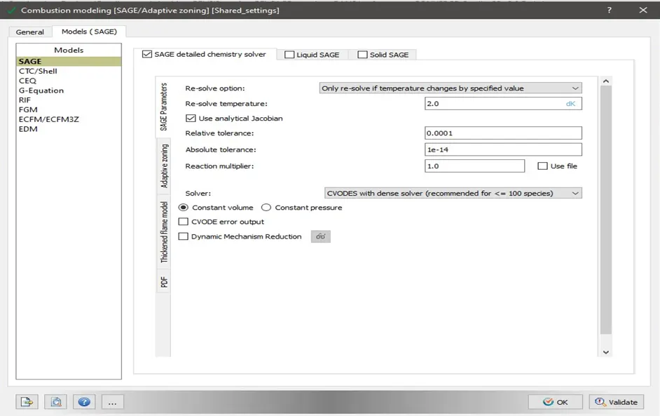
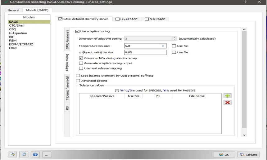
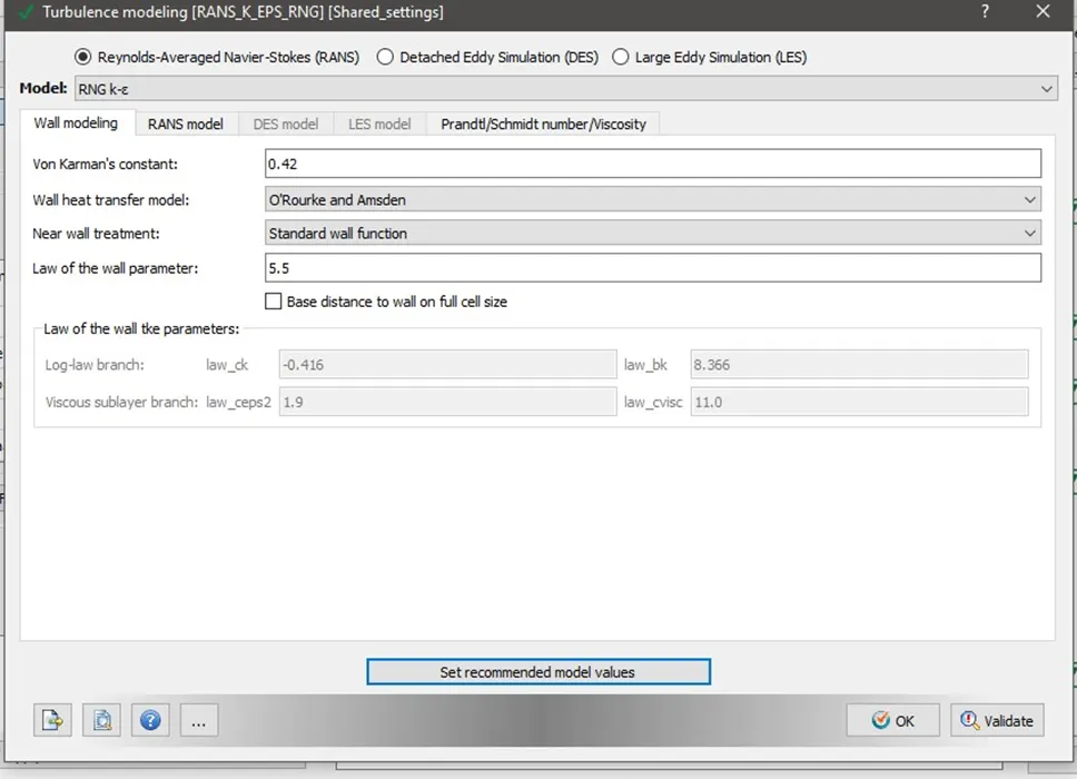
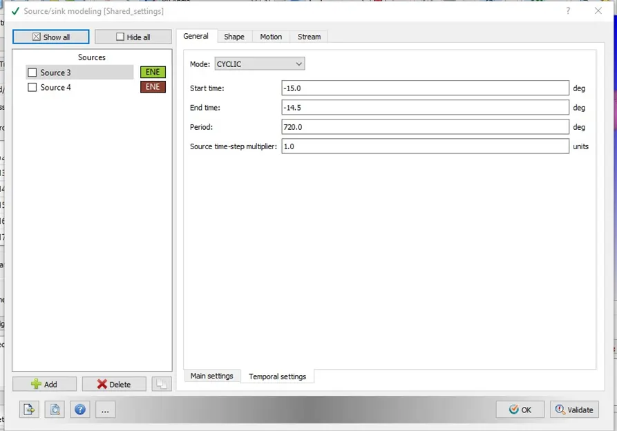
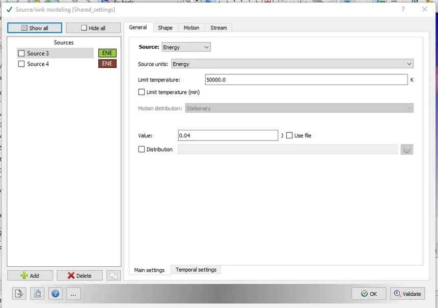
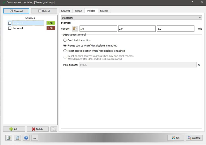
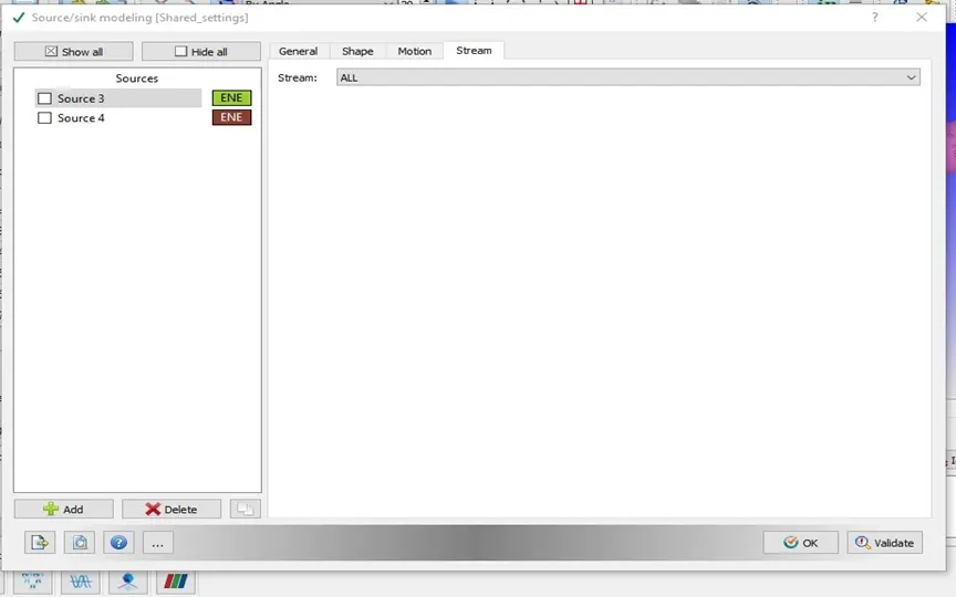
We select Parcels modeling, Combustion modeling, Turbulence modeling, and Source/sink modeling.
- Parcels configuratio
Parcels introductions
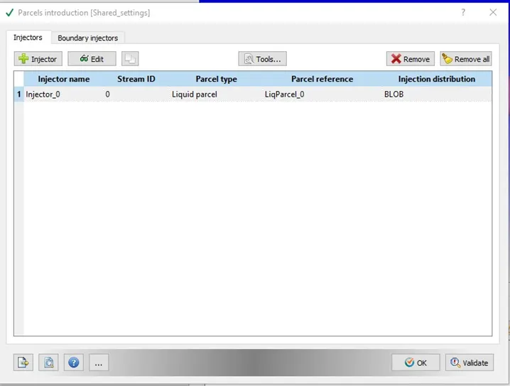
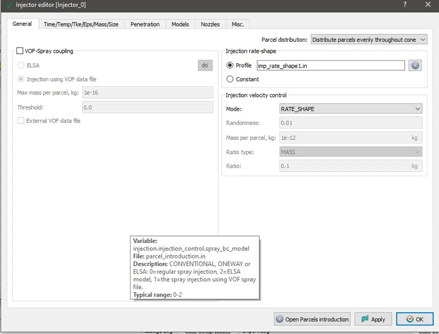
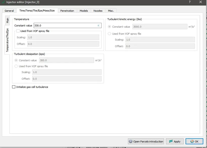
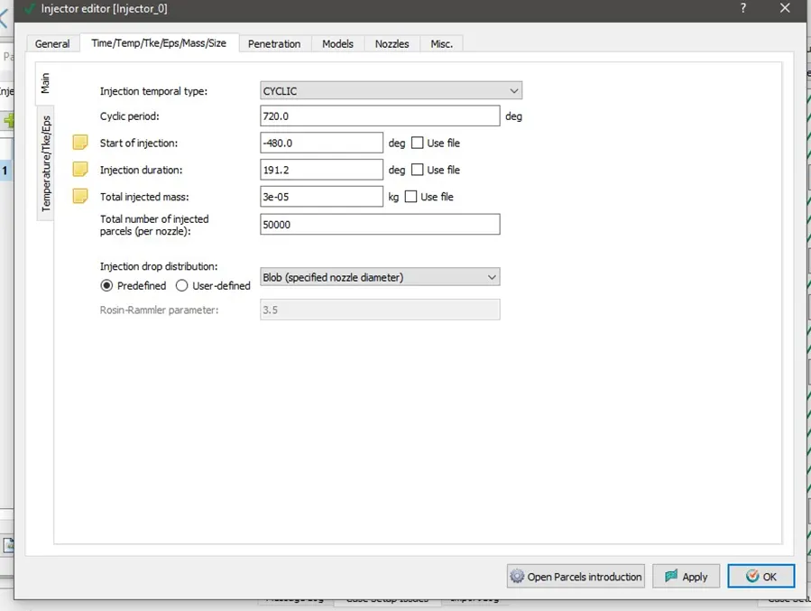
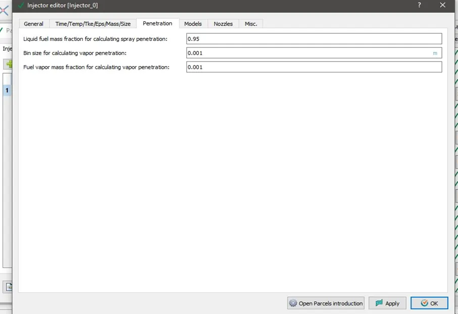
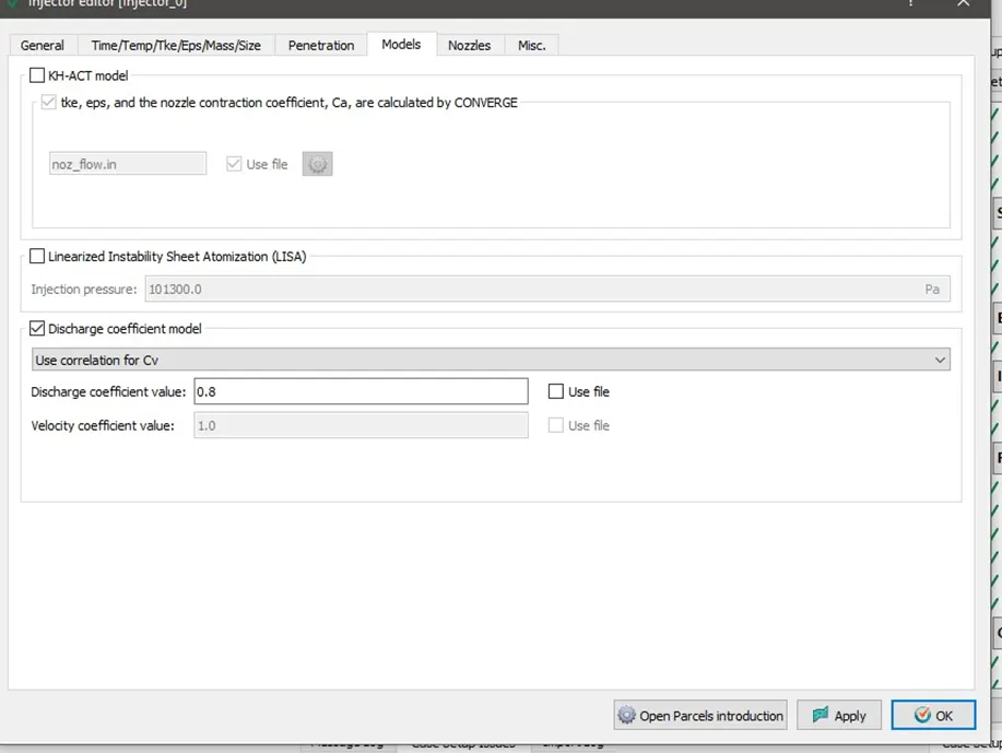
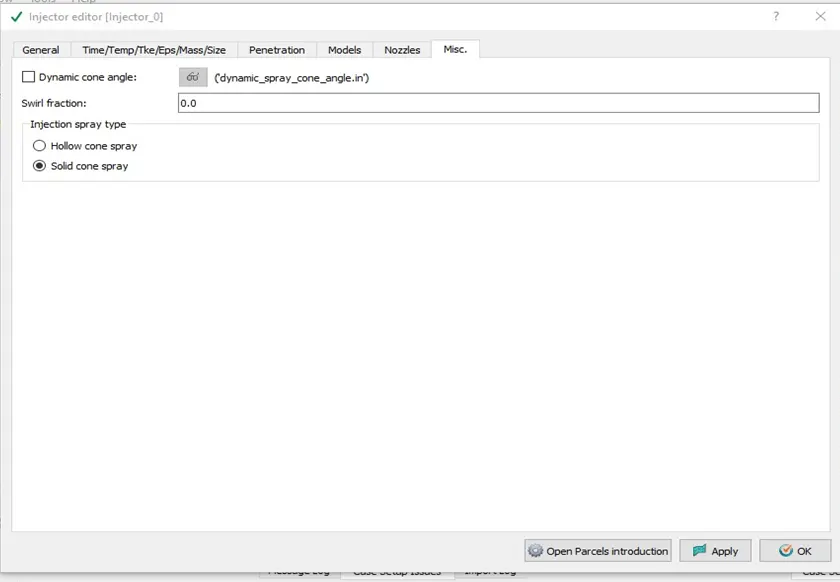
Injector r Nozzles
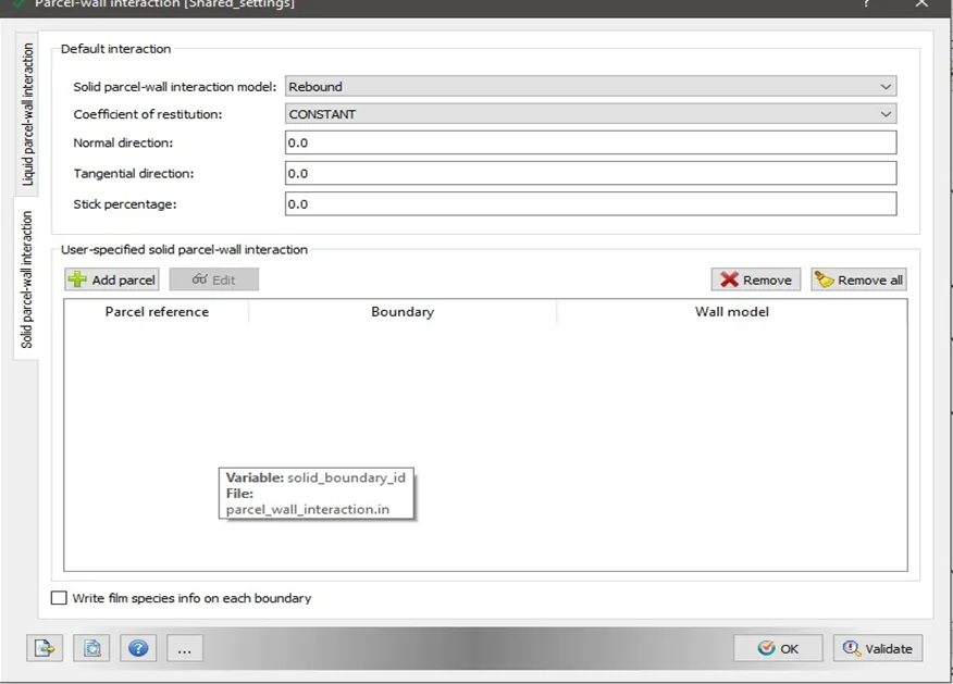
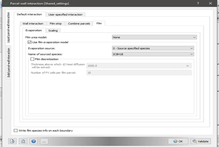
Parcels wall interaction
Combustion modeling
Turbulence model
Source modeling
Grid Control:
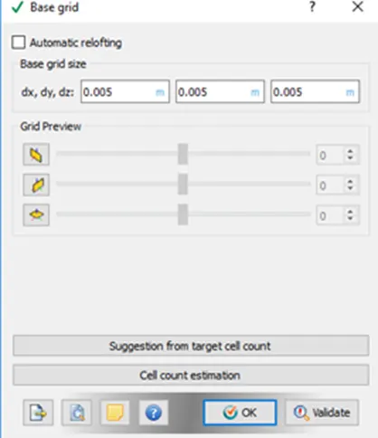
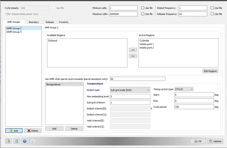
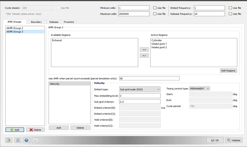
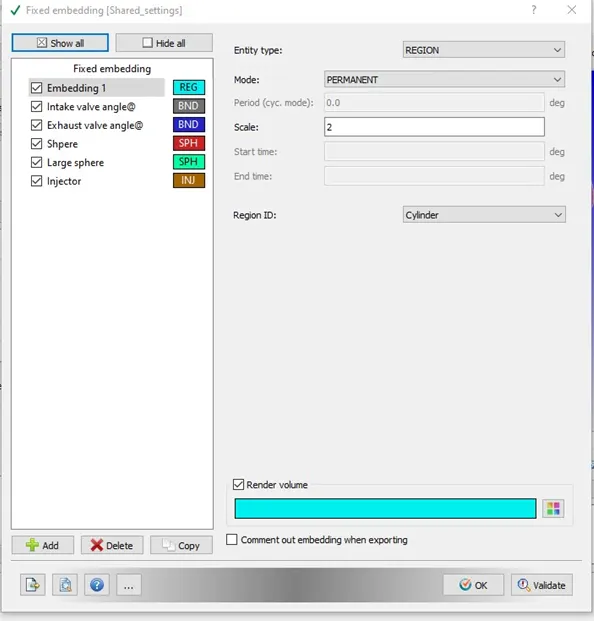
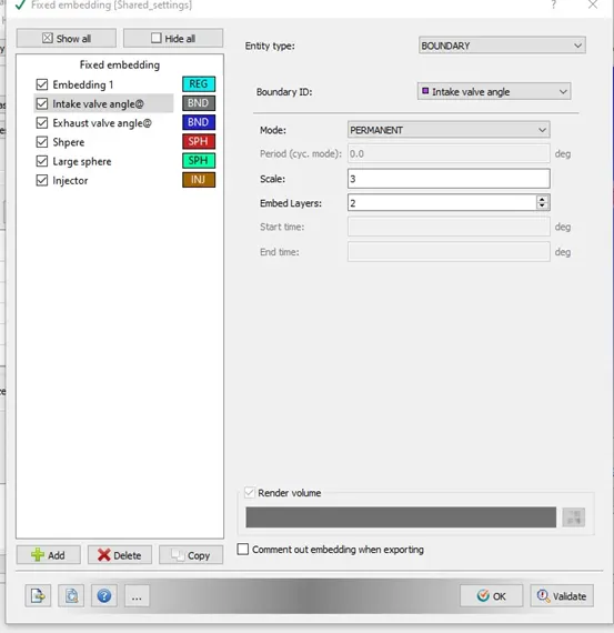
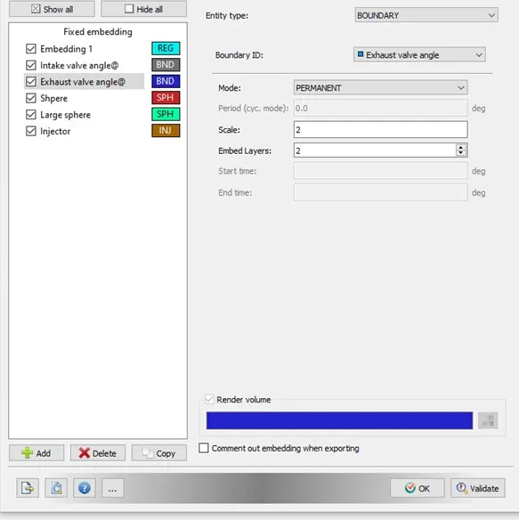
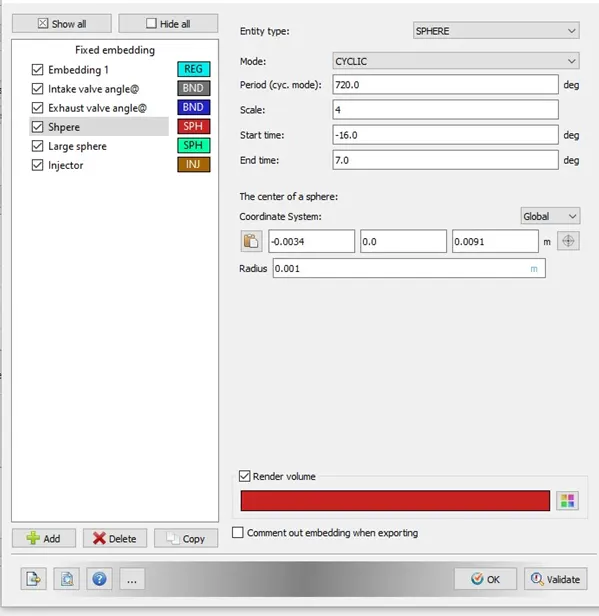
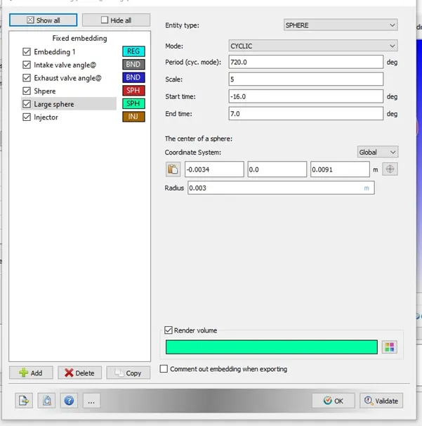
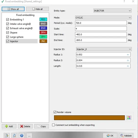
We select Base grid, Adaptive mesh refinement, and Fixed embedding.
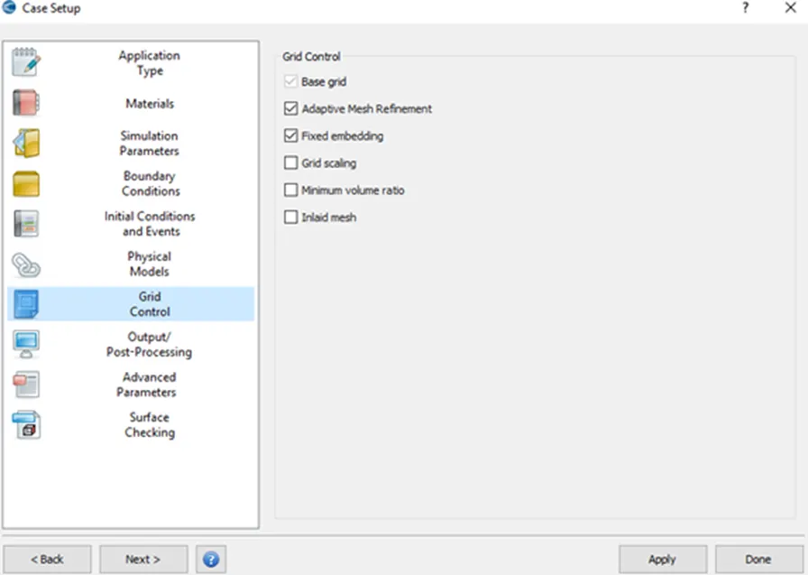
Base grid
Adaptive mesh refinement
Fixed embedding
Results:
Compression Ratio
In a reciprocating engine, the piston oscillates between the Top dead center and the bottom dead center. These correspond to the minimum and maximum values respectively. The ratio between these two volumes is known as the compression ratio.
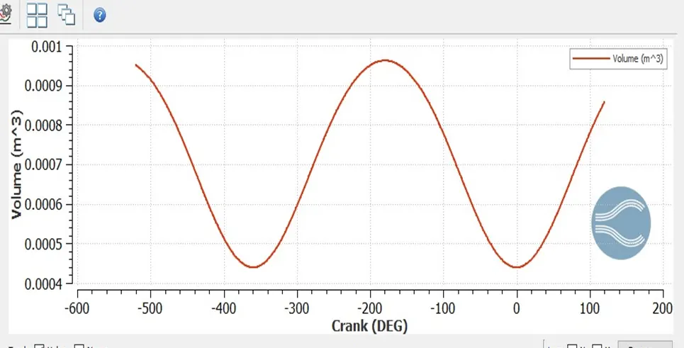
From the above graph we, note tha
Maximum Cylinder Volume = 5.74186∗10−4m3
Minimum Cylinder Volume = 5.73996∗10−5 m3
Compression ratio = 5.74186∗10−4 / 5.73996∗10−5
Compression ratio = 10
Combustion efficiency of the Engine
Combustion efficiency is defined as the energy released by the burnt fuel to the theoretical energy content of the fuel.
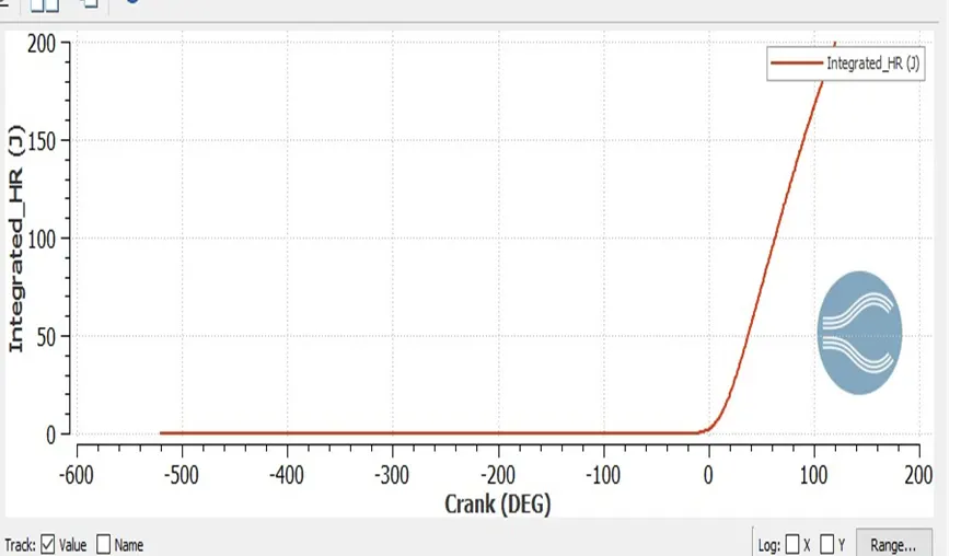
ηcombustion= (Integrated Heat Release rate)/(mass of fuel * LHV)
Integrated Heat Release Rate= 1241.15 J
mass of fuel = 3x10^-5 kg
LHV = 43.4 MJ/kg
ηcombustion = 1241.15 / 3∗10−5∗43.4*10e6 = 95.3 %
Need for Wall Heat Transfer model
Heat loss through the cylinder walls has a detrimental impact on the performance of the engine. Some of the undesirable effects include a reduction in volumetric efficiency, incomplete combustion, etc. The description of heat transfer in an ICE is a challenging task, considering the different systems (intake and exhaust ports, coolant circuit, lubricant oil subsystem), the different heat transfer mechanisms (convection, conduction, and radiation), and the rapid and unsteady changes that take place inside the cylinder. So there is a need to accurately model this phenomenon. Due to the complexity involved in a mathematical solution, there is a need to adopt suitable modeling.
Why we cannot use CFD to predict wall temperature?
CFD can provide precise and instantaneous information about the flow within the engine (temperature, pressure, velocity distributions), but require temperature boundary conditions for the engine walls, which are typically assumed as being constant throughout the engine cycle. This will affect the combustion process, thus leading to inaccurate results Imposing appropriate wall temperature boundary conditions is not an easy task, and may require some iterative process. However, such calculations with a given surface temperature are not sufficient when the focus is on analyzing the heat transfer within the engine. The heat flux and gas properties of the CFD are used as boundary conditions for the heat conduction calculation of the solid regions.
Significance of CA10, CA50, and CA90
The CA10, CA50, and CA90 are defined as positions of the crank angle at which the cumulative heat release rate reaches 10%, 50 %, and 90%. The physical significance of CA10 is that it is used to signify the start of ignition in an engine, while CA 50 signifies the end of pre-mixed combustion and the start of diffusion combustion of fuel used in the engine. The greater the difference between CA10 and CA50, the higher the duration of combustion and vice versa
Plots
- Cylinder Pressure
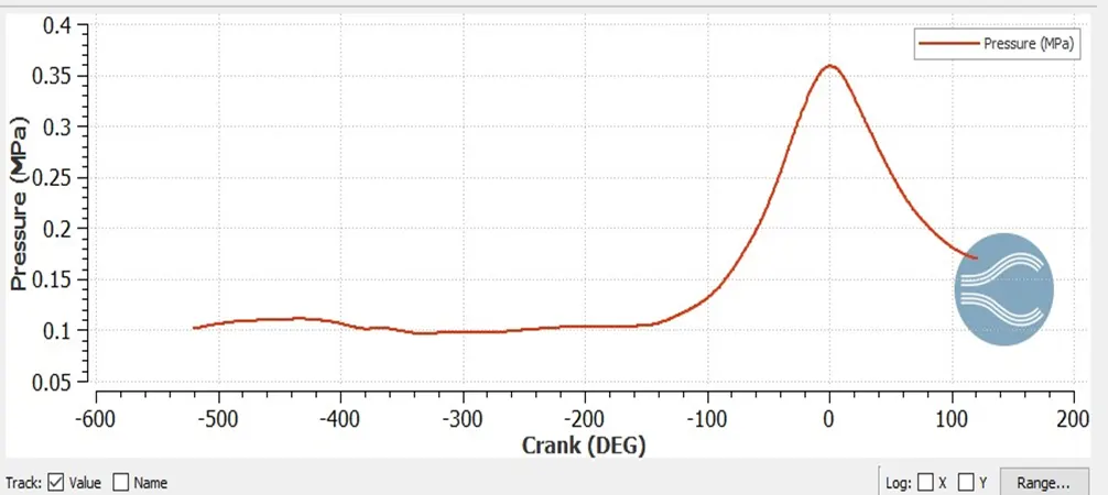
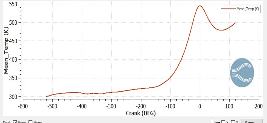
Mean Temperature
Calculate the combustion efficiency of this engine
In real engine applications, the combustion process is incomplete. This means that not all the energy content of the fuel supplied to the engine is released through the combustion process. There are several factors which can influence the combustion process, the most important being the fuel-air intake and fuel atomization (size of droplets). The fuel inside the cylinder needs air (oxygen) to burn. If there is not enough oxygen available, not all the fuel is burnt, therefore only a partial energy is released from combustion (e.g. around 96 %). If we analyze the exhaust gas of an internal combustion engine, we can see that it contains both incomplete combustion products (carbon monoxide CO, nitrogen oxides NOx, unburnt hydrocarbons HC, soot PM) and complete combustion products (carbon dioxide CO2 and water H2O).
The combustion efficiency ηc is defined as the ratio between the energy released by the burnt fuel and the theoretical energy content of the fuel mass during one complete engine cycle.
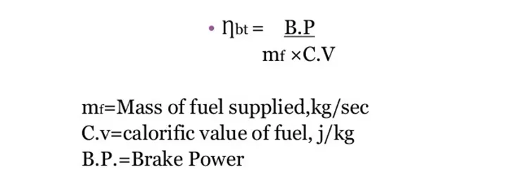
Where,
C.v = 44000 KJ/Kg
mf = 3e-5 Kg.
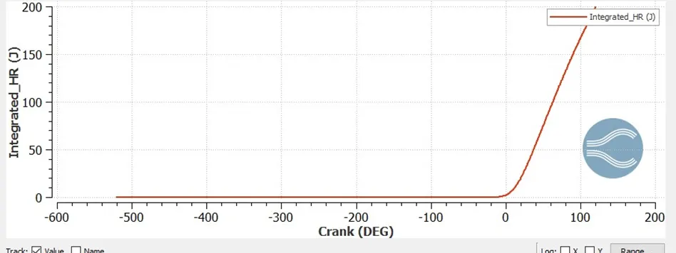
Combustion efficiency ηc = 1.241 (KJ) / 44000 (KJ/Kg) * 3e-5 Kg
ηc = 0.94 (i.e) 94%
Use the engine performance calculator, to determine the power and torque for this engine.
To open performance calculator go to Line plotting in converge CFD.
Go to Tools --> Engine calculators --> Engine performance.
Give the thermo.out file for the cylinder region as the input file for calculating the engine's performance.
Power Calculation
To calculate power we can use the formula; Power = Work/sec
From performance calculator we can take;
Work = 39.18 Nm
Start time = -180.53 deg
End time = 120.165 deg
Total duration = 302 deg
Total rotation per minute RPM = 3000 (Given)
Rotation per second = 3000/60 = 50.
Total degree per second = 50*360 = 18000
Time in sec = 302/18000 = 0.0168 sec.
Power = 17978/0.0168
Power = 17976.19 Kj = 18 KW
Torque Calculation
power = (2*pi*N*T)/60
T = power * 60/ (2*pi*N)
N = 3000 RPM.
T = 18 *1000* 60 / (2*3.14*3000) = 1080000/18840
Torque(T) = 57.879 Nm. It is half cycle
For 720 deg torque is 116 Nm
Animation video
https://youtu.be/nLMV-8BT3LM
Conclusion
In this project, a detailed simulation of the IC engine has been carried out. In the case setup, spray and combustion modeling was set up. The movement of piston, intake, and exhaust valves was created using regions and events. Mesh refinement techniques such as AMR and Fixed embedding were adopted to obtain finer results.
After simulation and post-processing, engine performance parameters such as compression ratio, power, and torque were computed and are listed below
Compression Ration=10.1
Power = 36 Kw
Apart from this, other aspects such as cylinder mean temperature and pressure, liquid particles, and emissions were studied as a function of a crank angle. Also, animations for temperature and spray modeling were examined.