Week 10 Challenge
Aim:-
- To list out the checks that need to be followed in the design of well foundation regarding the stability and the design also list out all the necessary clauses from IRC codes applicable.
- Explanation: -
- The checks that are needed to be done for stability and design of well foundations also the clause related to it are as follow: -
- Explanation: -
| Sr.No | Checks to be done for stability & design | IRC-78-2000 Clause |
| 1 | Load, force & their combination | 706.1 |
| 2 | Horizontal force at bearing level | 706.2 |
| 3 | Base Pressure | 706.3 |
| 4 | Allowable settlement/Differential settlement | 706.3.2 |
| 5 | Permissible tension at the base of the foundation | 706.3.3 |
| 6 | The factor of safety for stability | 706.3. |
Aim: -
-
To list out the limits in ULS and SLS for the design of an RCC component. Define the limit states and the factors in it as per IRC 112. Also mention shear checks. what is the difference in shear with/without reinforcement?
- Explanation: -
- Limits in ULS for the design of RCC components are as follow: -
- Ultimate limit state ULS, the limit state of equilibrium when subjected to various design combinations of ultimate loads the bridge or any of its components considered as a rigid body shall not become unstable, so this is the one equilibrium as a whole it should be equilibrium position. And limit state of strength the bridge or any of its components shall not lose its capacity to sustain the various ultimate load combinations by excessive deformation, transformation into the mechanism, rupture, crushing, or buckling. So that is the one we can consider that as a part of the limit state of strength. The next one is called under ultimate limit states, so the limit state of equilibrium that is we are not going to internal stresses that from externally whether it is in stable condition or not equilibrium condition then limits state of strength we are considering that one the stresses.
- According to IRC-112, their are various ULS limits that are
- Ultimate limit state of linear elements for bending and axial forces, section-8, IRC-112-2011.
- Ultimate limit state of 2 & 3-dimensional elements for out of the plane and in planned loading effects, section-9, IRC-112-2011.
- Ultimate limit state of shear, Punching shear & torsion, section-10, IRC-112-2011.
- Ultimate limit state of induced deformation,section11, IRC-112-2011.
- Limits in SLS for the design of RCC components are as follow: -
- Serviceability limit states SLS, limit state of internal stress; the internal stresses developed in the materials of structural elements shall not exceed the specified magnitudes when subjected to the combination of serviceability designations. The stresses are to be estimated using resistance models to represent the behavior of structure as stipulated in the code, so this is the one we shall consider for internal stress.
- According to IRC-112, there are various SLS limits that are
- Stress limitation, section 12.2, IRC-112-2011.
- Limit state of cracking, section 12.3, IRC-112-2011.
- Limit state of deflection, section 12.4, IRC-112-2011.
- Shear checks: -
- Current practice in the world for shear design many various practices is going on, As Shear is more critical force than other actions on bridge’s
members, new code IRC 112:2011 has improved in shear criteriacompare to old IRC 21:2000. -
Parameters IRC-112-2011 Analysis Specified Min steel,Asw Different for inclined and vertical Max steel, Asw,max Specified for both inclined and vertical Shear steel design for T-flanged section Specified Min steel depend upon Take ratio of fy & fck -
LIMIT STATE METHOD, IRC 112:2011
Equations used are,
1. Clause 10.3.2,page 88
𝑉𝑅𝑑𝑐 = [0.12𝐾(80 ∗ 𝜌𝑙 ∗ 𝑓𝑐𝑘)0.33 + 0.15 ∗ 𝜎𝑐𝑝] ∗ 𝑏𝑤 ∗ 𝑑2. Clause 10..3.3.2, page-90 for vertical shear reinforcement
VRds = Asw/s *z*fywd*cot θ
VRd,max = αcw*bw*z*v1*fcd/(cot θ + tan θ )
Asw,max * fywd/bw*s ≤ 0.5*αcw*v1*fcd3. Clause 10.3.3.3,page 91,for Inclined shear reinforcement.
4. Clause 10.3.3.5,page-95, Min. reinforcement ratio :ρmin = 0.072*√fck /fyk
VRds = Asw/s *z*fywd*(cot θ+ cot αl)
VRd,max = αcw*bw*z*v1*fcd*(cot θ +cot αl)/(1+ cot2 θ)
Asw,max*fywd / bw*s ≤ 0.5* αcw*v1*fcd / sin αl l - Difference in shear with/without reinforcement
- The design of concrete members for shear without stirrups has become a major issue worldwide especially for bridge decks as the shear capacity according to the ‘new’ regulations often gives significant smaller values than the one predicted by former codes. Therefore nowadays stirrups are required in bridge decks. In addition the safety of existing structures mainly build without shear reinforcement has been brought into focus.
- Members loaded beyond their shear capacity need to be provided with shear reinforcement to resist the full shear force (Cl. 10.2.2.1 IRC-112-2011)
- The shear design has to be carried out under ultimate limit state only. When the member requires shear reinforcement, the reinforcement has to be calculated based on a truss model. For members without shear reinforcement the capacity of the section is estimated using empirical formula.
- Current practice in the world for shear design many various practices is going on, As Shear is more critical force than other actions on bridge’s
- Limits in ULS for the design of RCC components are as follow: -
- Explanation: -
Aim: -
- To discuss in detail about calculation of steining thickness and steel.
- Explaination: -
-
The existing practice in India is to decide the thickness of well foundation based on the formula given by Indian Roads Congress Code (IRC:78-2014) which is based on the assumption that steining should be rigid and thickness of steining should be sufficient for self-sinking of well to reduce sinking efforts and to avoid excessive loading during sinking. However the formula given by the code results in pretty high thickness which increases the cost of project especially in the case of large wells. Indian Railway code on “design & construction of well & pile foundation” mentions that the steining thickness should be sufficient to enable sinking without excessive kentledge and provide adequate strength against forces acting on the steining both during sinking and service. However no formula for well steining is provided in Indian Railway code. It is shown that considerable reduction in thickness of well can be achieved when the thickness of well is calculated using the first principle methodology followed by the authors like Terzaghi & W.C.Teng compared to the thickness calculated by the formula given by IRC:78-2014.
- Thickness of steining & reinforcement : - According to the clause 708.2.3.1 of IRC:78-2014 [2] the steining thickness will be given by the formula: h=k d √l
According to the code, the minimum thickness of steining should be 500 mm. The formula is code is based on the assumption that steining should be rigid and thickness of steining should be sufficient for self-sinking of well to reduce sinking efforts and to avoid excessive loading during sinking.However Terzaghi,[3] in his book “Soil Mechanics in Engineering Practice” on Page No. 468 has mentioned following regarding well sinking:“While excavation is being carried on within a caisson of the drop-shaft type, the soil next to the caisson is supported laterally by the walls of the shaft. Sections are added to the shaft above the ground surface, and as excavation proceeds, the caisson slides down. The downward movement is resisted by skin friction. To overcome the skin friction, lightweight drop shafts, such as those of steel, must be loaded with dead weights. On the other hand, heavy caissons, such as those of concrete, may descend under their own weight.”
-
708.3.5. In case where the well steining is designed as a reinforced concrete element, it shall be considered as a column section subjected to combined axial load and bending. However, the amount of vertical reinforcement provided in the steining shall not be less than 0.2 per cent. (for either mild steel or deformed bars) of the actual gross sectional area of the steining. On the inner face, a minimum of 0.06 per cent (of gross area) steel shall be provided. The transverse reinforcement in the steining shall be provided in accordance with the provisions for a column but in no case shall be less than 0.04 per cent of the volume per unit length of the steining.
-
The horizontal annular section of well steining shall also be checked for ovalisation moments by any rational method taking account of side earth pressures evaluated as per Claus 708.4.
- 708.3.6. The vertical bond rods in brick masonry steining shall not be less than 0.1 per cent of the cross-sectional area and shall be encased into cement concrete of M 15 mix of size 150 mm x 150 mm. These rods shall be equally distributed along the circumference in the middle of the steining and shall be tied up with hoop steel not less than 0.04 per cent of the volume per unit length of the steining. The hoop steel shall be provided in a concrete band at spacing of 4 times of the thickness of the steining or 3 metres, whichever is less. The horizontal RCC bands shall not be less than 300 mm wide and 150 mm high, reinforced with bars of diameter not less than 10 mm placed at the corners and tied with 6 mm diameter stirrups at 300 mm centres, as shown in the Appendix-3, (Fig. 3).
- 708.3.7. The stresses in well steining shall be checked at such critical sections where tensile and compressive stresses are likely to be maximum and also where there is change in the area of reinforcement or in the concrete mix.
-
- Explaination: -
Aim: -
- To discuss in detail the spacing of pile is determined in 6 pile system & also describe the bulb theory with neat diagrams showing the stress distributions.
- Explaination: -
-
Spacing of piles and tolerances
Spacing of piles: The spacing of piles should be considered in relation to the nature of the ground, their behaviour in groups and the overall cost of the foundation. The spacing should be chosen with regard to the resulting heave or compaction and should be wide enough to enable the desired number of piles to be installed to the correct penetration without damage to any adjacent construction or to the piles themselves.
The cost of a cap carrying the load from the structure to the pile heads, or the size and effective length of a ground beam, may influence the spacing, type and size of piles.
The spacing of piles will be determined by:
(a) the method of installation, e.g., driven or bored;
(b) the bearing capacity of the group.
Working rules which are generally, though not always, suitable, are as follows:
For friction piles, the spacing centre should be not less than the perimeter of the pile or, for circular piles, three times the diameter. The spacing of piles deriving their resistance mainly from end bearing may be reduced but the distance between the surfaces of the shafts of adjacent piles should be not less than the least width of the piles.
-
Permissible tolerances for piles shall be as under
(i) For vertical piles 75 mm at piling platform level and tilt not exceeding 1 in 150.
(ii) For raker piles tolerance of 1 in 25.
-
The maximum rake to be permitted infiles shall not exceed the following
-
1 in 6 for all bored piles:
-
1 in 6 for driven cast-in-situ piles, and
-
1 in 4 for precast-driven piles.
-
- The minimum diameter of piles shall be as: -
-
Land Bridge River Bridge Driven Cast-in-suit pile 0.5 m 1.2 m Precast Pile 0.35 m 1.0 m Bored Pile 1.0 m 1.2 m
-
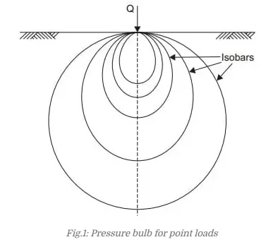
- Pressure bulb Theory: -
- An isobar or pressure bulb is a stress contour or a line which connects all points below the ground surface at which the vertical pressure is the same. In fact, an isobar is a spatial curved surface and resembles a bulb in shape; this is because the vertical pressure at all points in a horizontal plane at equal radial distances from the load is the same. Thus, the stress isobar is also called the ‘bulb of pressure’ or simply the ‘pressure bulb’. The vertical pressure at each point on the pressure bulb is the same. Pressure at points inside the bulb are greater than that at a point on the surface of the bulb; and pressures at points outside the bulb are smaller than that value. Any number of pressure bulbs may be drawn for any applied load, since each one corresponds to an arbitrarily chosen value of stress. A system of isobars indicates the decrease in stress intensity from the inner to the outer ones and reminds one of an ‘Onion bulb’. Hence the term ‘pressure bulb’. An isobar diagram, consisting of a system of isobars appears somewhat as shown in Fig
-
- Explaination: -
- Aim: - To calculate the reaction exerted on the group of piles from the pier of the bridge.
- Given Data: -
- Total vertical reaction = 5929 kN
- Total moment about L-L axis = 1092 kN.m
- A total moment about the T-T axis = 530 kN.m
- Total horizontal force along L-L axis = 83kN
- Total horizontal force along T-T axis = 172 kN
- Plan: -
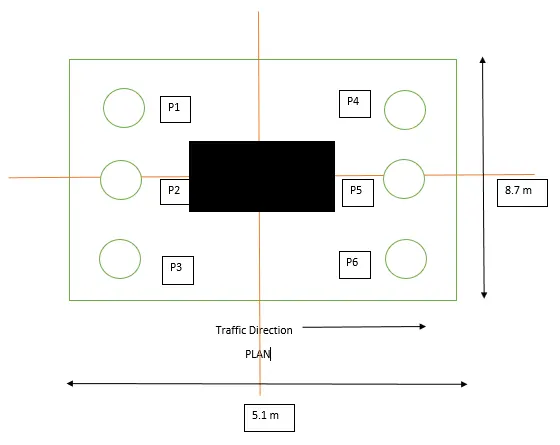 .
.- Load on each pile = [P/n]±[Mx*x/∑x2]±[My*y/∑y2]
- p = Vertical load on the pile cap
- n = Numer of the pile in a group
- Mx = Total moment due to force in X-axis
- My = Total moment due to force in Y-axis
- ∑x2 = Sum of the square of the distance of pile in X-direction
- ∑y2 = Sum of the square of the distance of pile in Y-direction
- x = Distance of pile from the Y-axis
- y = Distance of pile from the X-axis
- Given Data: -
- For pile P1
- ∑x2 = 3*1.8^2+3*(-1.8^2); = 19.44 m^2
- ∑y2 = 2*3.2^2+2*(-3.2^2); = 40.96 m^2
- Load on pile P1
- =5929/6+{530*(-1.8)/19.44}+{1092*(3.2)/40.96}; = 1024.676 kN
- Load on pile P2
- =5929/6+{530*(1.8)/19.44}+{1092*(3.2)/40.96}; = 1122.384 kN
- Load on pile P3
- =5929/6+{530*(-1.8)/19.44}; = 939.086 kN
- Load on pile P4
- =5929/6+{530*(1.8)/19.44}; = 1037.234 kN
- Load on pile P5
- =5929/6+{530*(-1.8)/19.44}+{1092*(-3.2)/40.96}; = 853.936 kN
- Load on pile P6
- =5929/6+{530*(1.8)/19.44}+{1092*(-3.2)/40.96}; = 952.150 kN