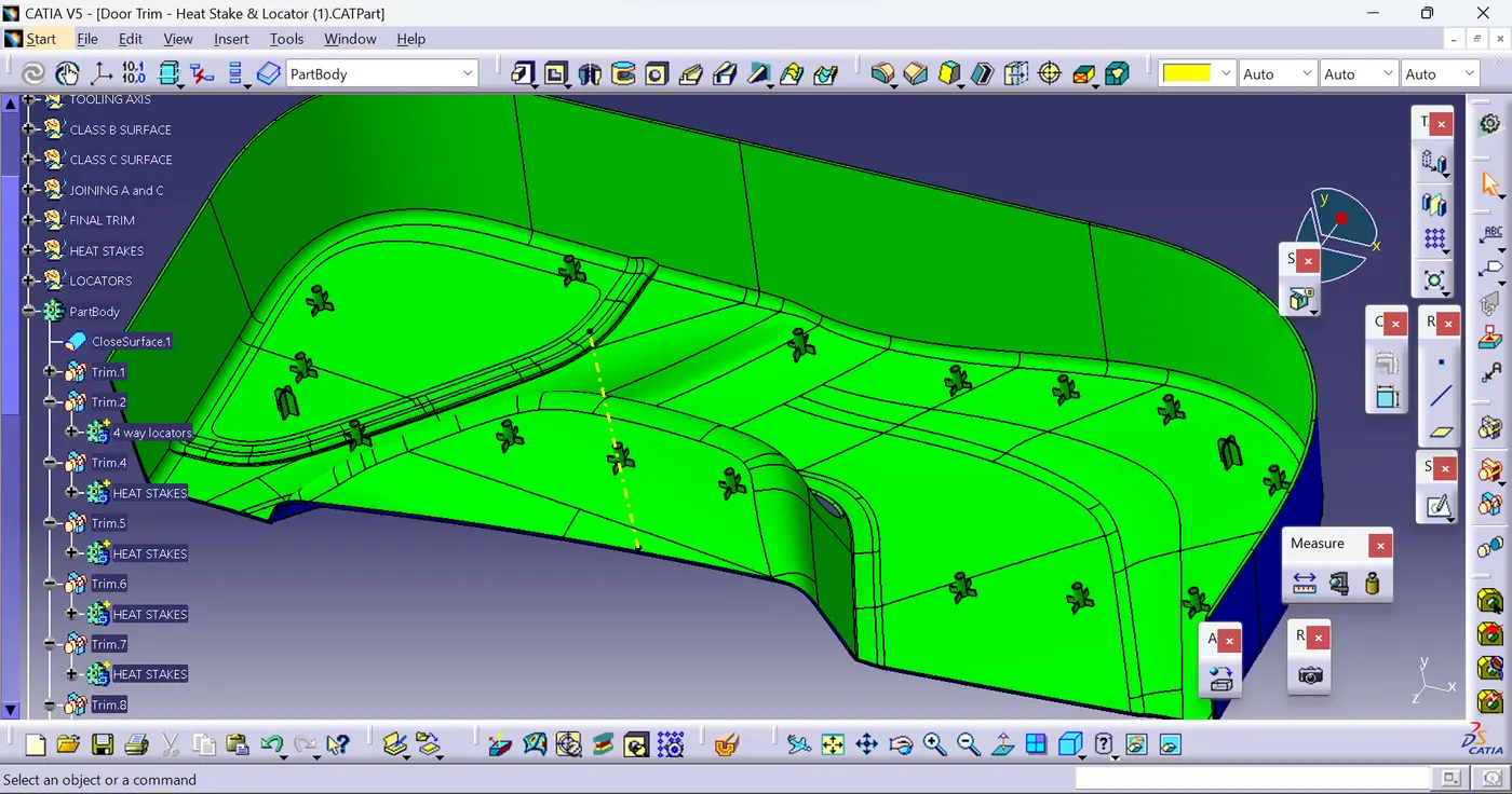
Week 10 - Challenge 3 - Door Trim Lower with Engineering Features
Objective:
- → Create Tooling axis for the given CLASS -A surface.
- → Create the CLASS B and C surfaces of door trim using the given CLASS-A surface.
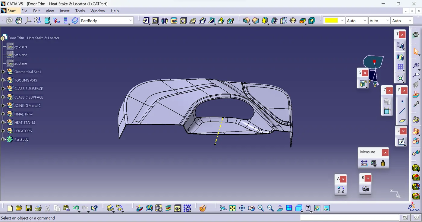
- → Create final surface model and convert it into solid body using close surface command in the part design workbench.
- → Create Locators and Heat stakes on the B side of the door trim part body.
- → Perform draft analysis for both Class-A surface and Final part body.
Tooling axis:
To create the tooling axis initially, I extracted the surface of class A with no propagation and I created the point at the centre of the extracted surface and created a line at that point in the Y direction. After creating the Tooling axis, I performed a draft analysis for class A to check the draft angle for it.
Draft analysis for class:
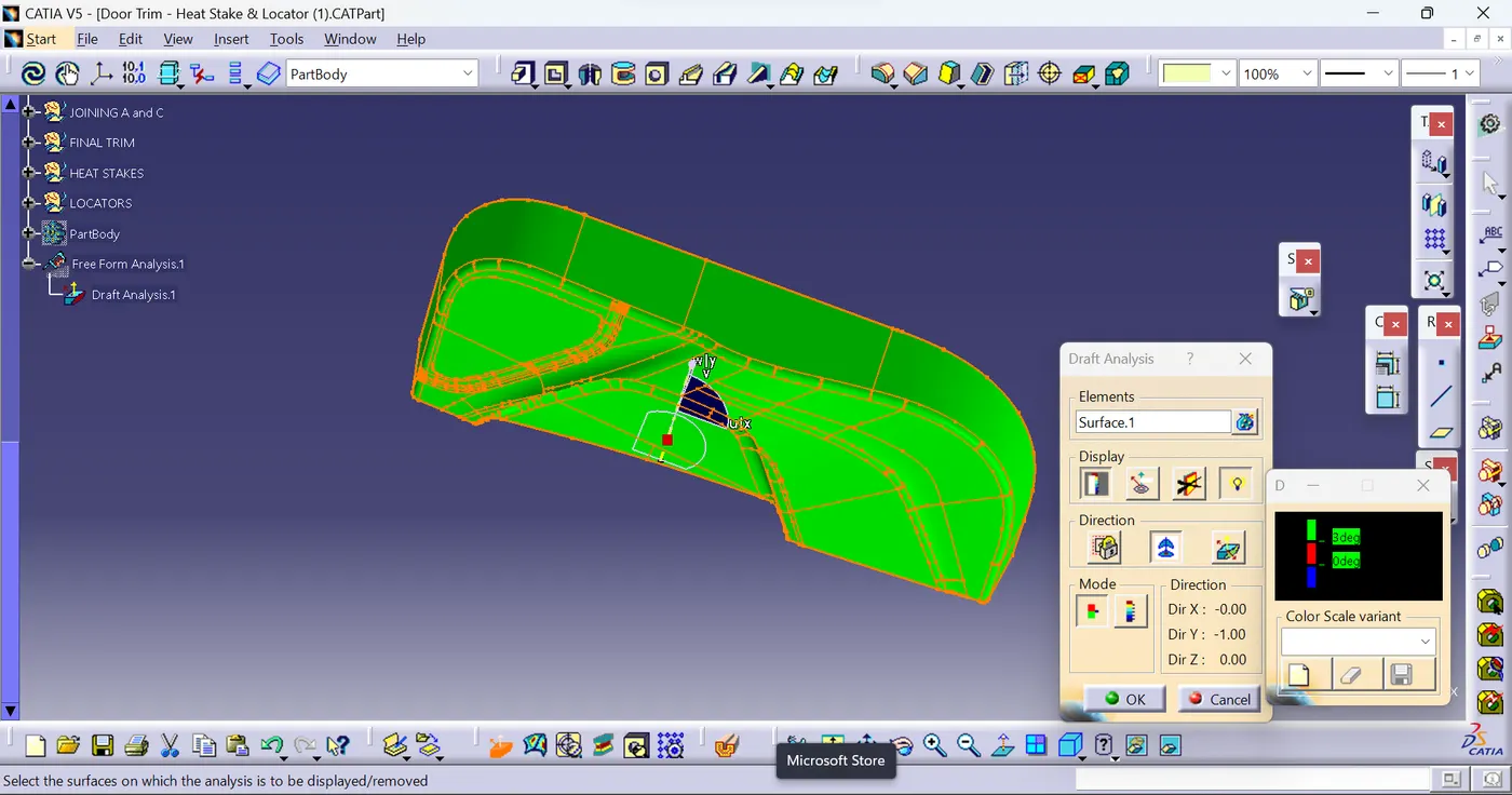
To perform the draft analysis in class A, I selected the featured draft analysis tool in the Generative shape design workbench. Initially, I click on the 'use of the compass to define the new current draft direction' command to align the compass to the tooling axis.
Once the compass is aligned to the tooling axis, we need to select the surface which we need to perform a draft analysis. Class A surface will be highlighted (in green colour) according to the colour bar angle and colours we defined in it.
Here I gave green colour for 3 deg, blue colour for < 0deg and red colour for less than 0.9deg and greater than 0deg.
I gave a 3deg draft angle all faces are getting cleared.
Draft angle 3deg:
A Solid body creation :To create the solid body I used the closed surface command in the part workbench. Click on the closed surface command in the part workbench and give the closed surface as an input to create the solid part body.
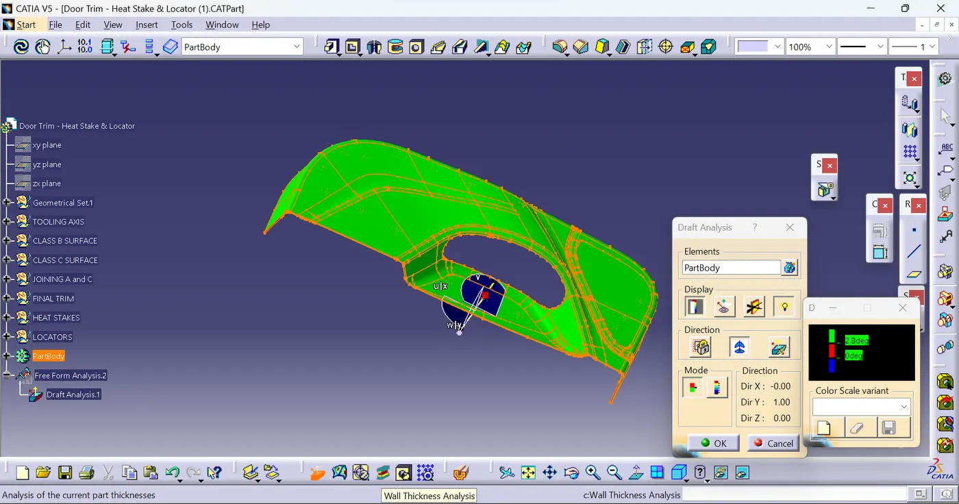
Draft analysis for the solid part body:
Heatstakes And locators: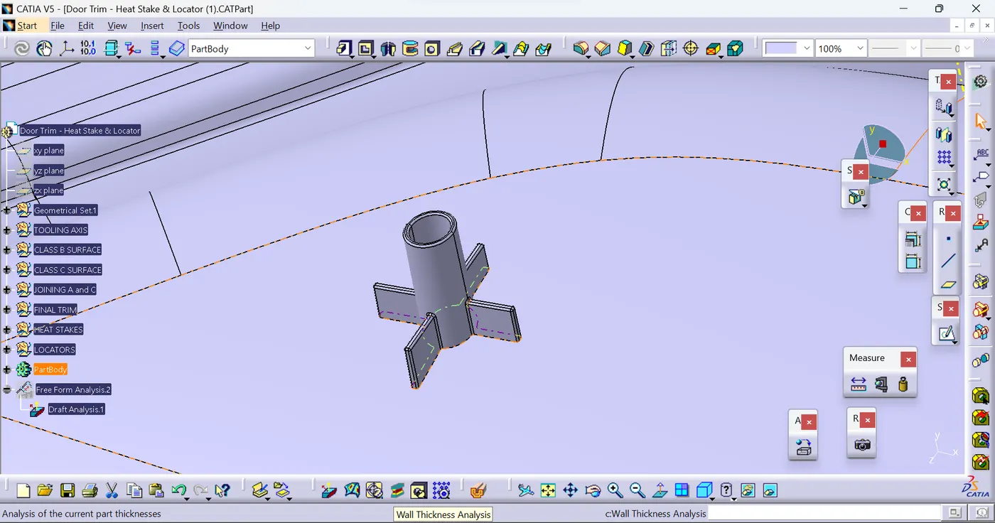
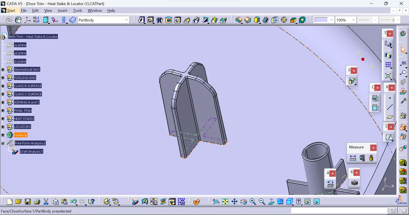
Draft analysis for the Solid part body with Heatstakes And locators: