Week 10 - Challenge 3 - Door Trim Lower with Engineering Features
DOOR TRIM LOWER
Aim: To Create the Door trim lower component through the given Class-A surface.
Objectives:
• Creation of Tooling axis with appropriate draft angle.
• Creation of other surfaces (eg, B and C surfaces) for creating a solid component. • Perform Draft analysis on Class A surface and Solid model hence created.
Tooling Axis creation:
It is defined as the direction in which the mould/core and cavity open. Selection of the direction of the tooling axis depends on the ease at which components can be easily ejected.
By analysing the component the most easily ejectable direction is somewhere close to the Z direction,(might be inclined to it) so we have made a sketch on the YZ plane of Axis System) to create a bisecting line considering the 2 faces which might be difficult to be tooled.
Draft Analysis
Same steps are followed to get the draft analysis of the solid part as in Class A Surface
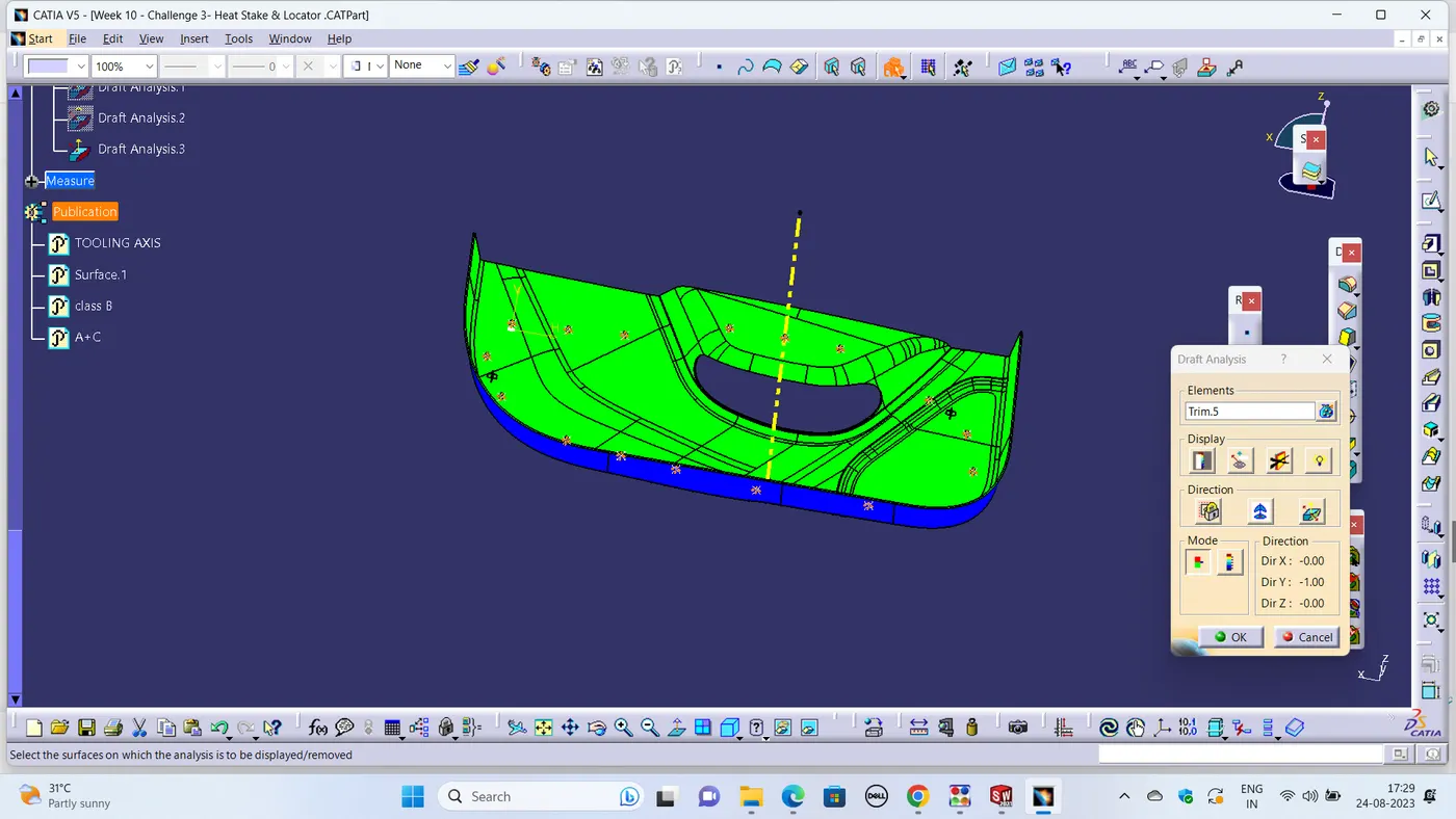
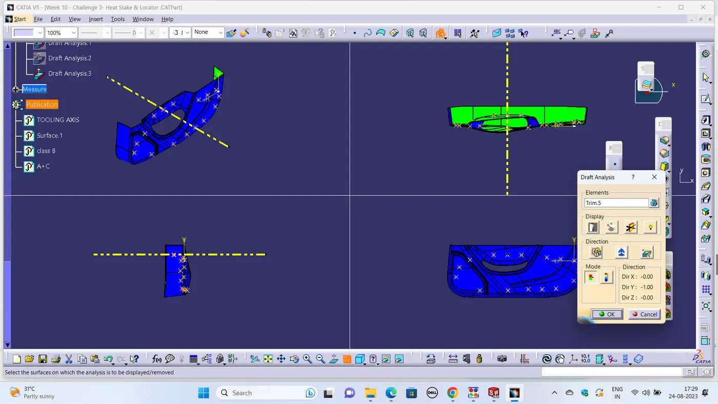
As we know minimum draft angle for the faces of the plastic component should be 3 degrees. So the value of 2.9 degrees (considering tolerance) is provided in the Draft analysis colour mode window Inside the colour scale, the GREEN bar shows the draft angle of 2.9 or above 2.9 degrees. The blue bar shows below 2.9 degrees draft angle the other limit being and the RED bar shows the negative draft angle. As shown in the image below all the top faces and side faces of the component are green, while the bottom faces are red. The line of demarcation between the green and red faces is the parting line which divides the core and cavity halves. The solid model has cleared the draft analysis successfully as shown in the image below.
Class B Surface:
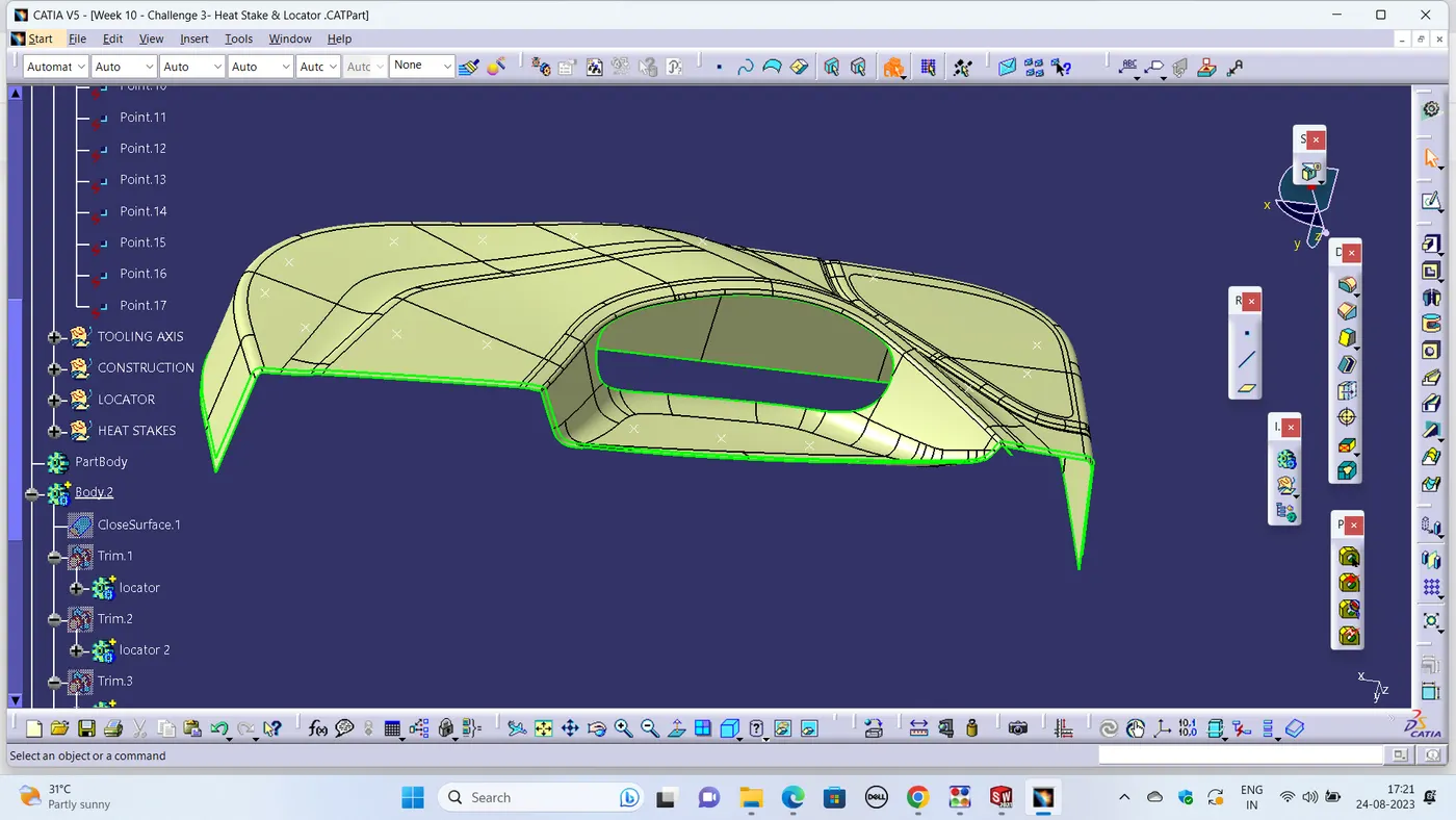
Kindly offset the class A surface to required thickness ie, 2.5mm , to get the class B surface.
Class C Surface:
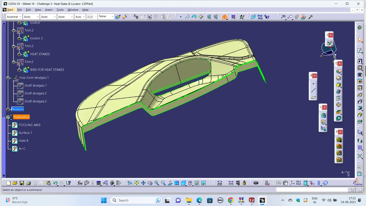
C surface has been created from the boundary lines of class A surface and by extracting the supporting surfaces then sweep the boundary lines with reference to the extracted surfaces.Create a sweep with reference to the draft direction and the reference surface with a 90 degree angle(for surface edges perpendicular to tooling axis)
Create a sweep with reference to the draft direction with a 3 degree angle(for surface edges parallel to tooling axis)
and give the inside direction Check for the continuity of the surfaces if there is any gap go for extrapolated and trim all together now we will get the class C surface
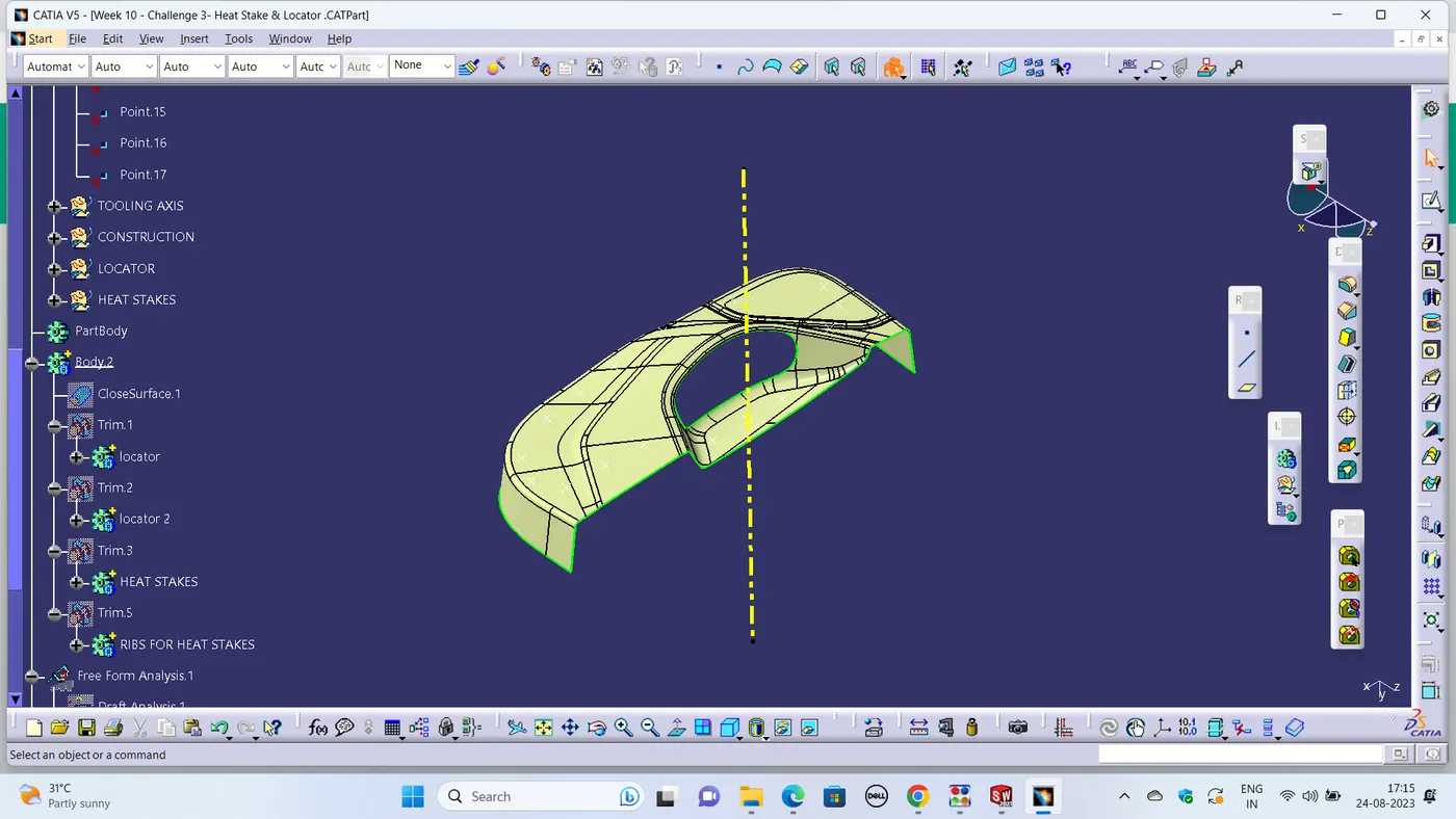
Closed Surface
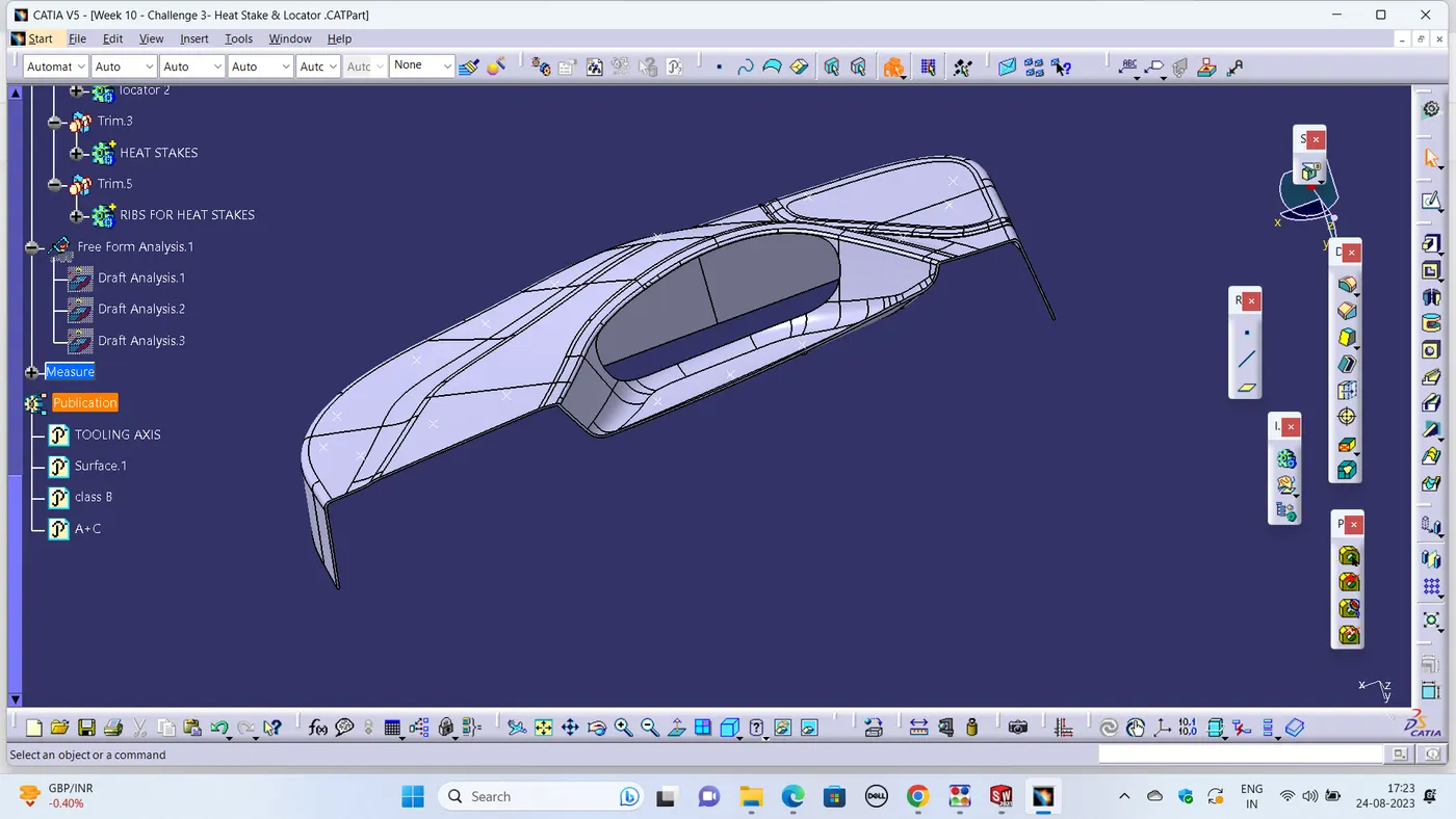
points are given for locate the Heat Stakes &locators
Create Heat stake. Draw a sketch on the surface. After the creation of the sketch, Pad it to 18mm height and a draft angle of 0.5deg on both sides (inside and outside) and then provide a fillet with a 0.25mm radius. After creating the heat stake, create the ribs for supporting purposes. To create the ribs, draw a sketch and padded it to height less than that of the heat stake and 1.3mm in thickness. After padding the ribs, drafted 0.5deg in the tooling axis direction and fillet it with a 0.20mm radius. Finally, use union trim on the ribs with a heat stake to remove the ribs as per the requirement, which are present inside the heat stakes.
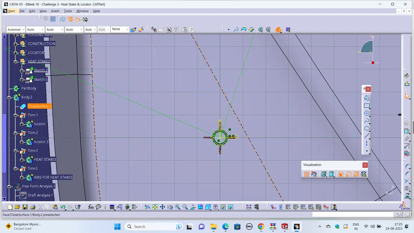
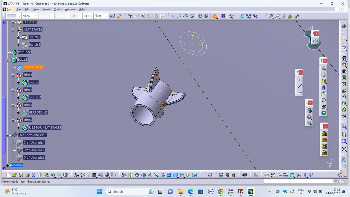
Create a 4 way locator using a sketch on the body. After creating the sketch, pad it 20mm in height and thicken it to 1.3mm and draft it with 0.5deg in the direction of the tooling axis. Give 3mm of chamfer with 45deg of inclination and a fillet of 0.30mm radius.
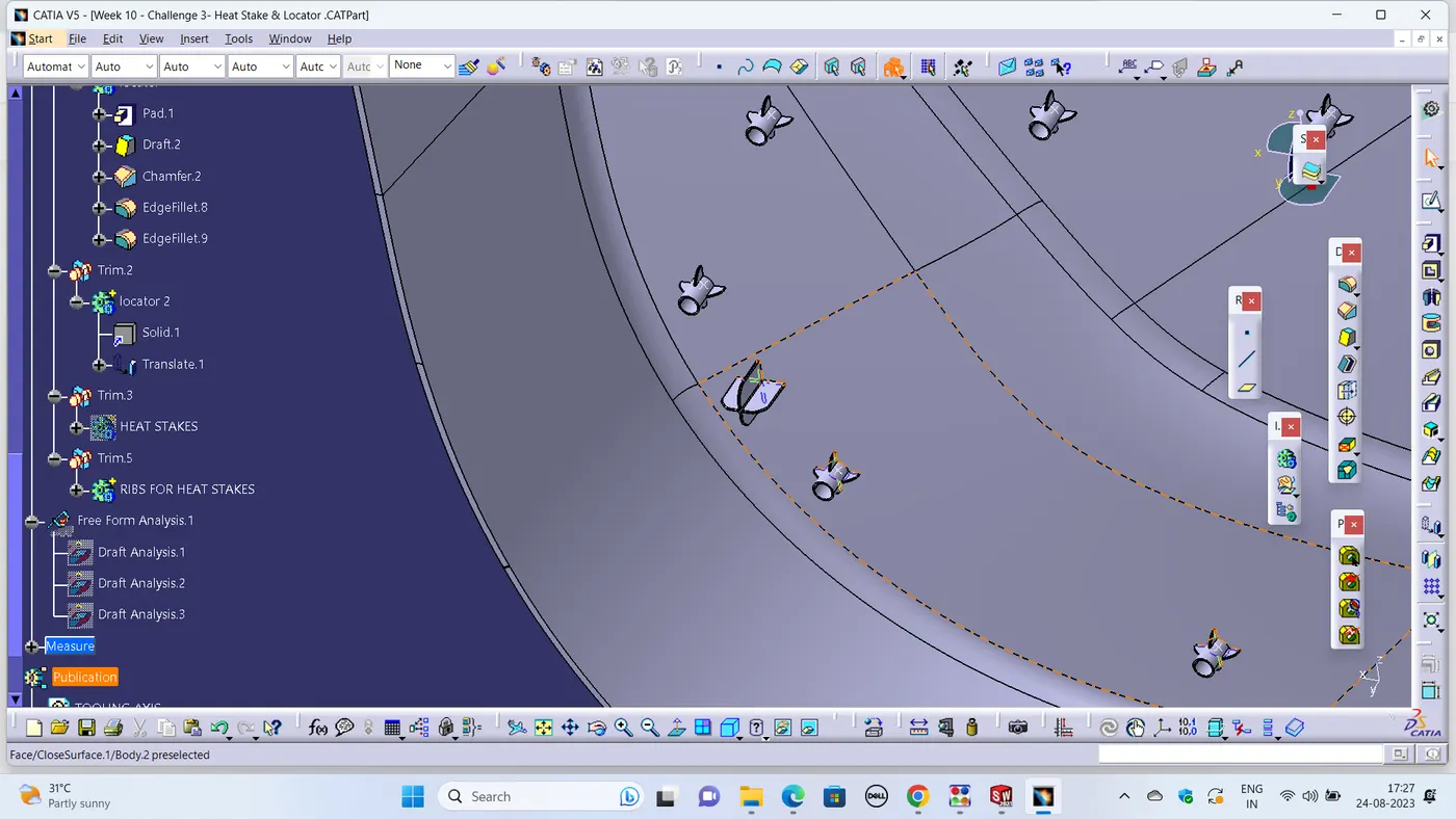
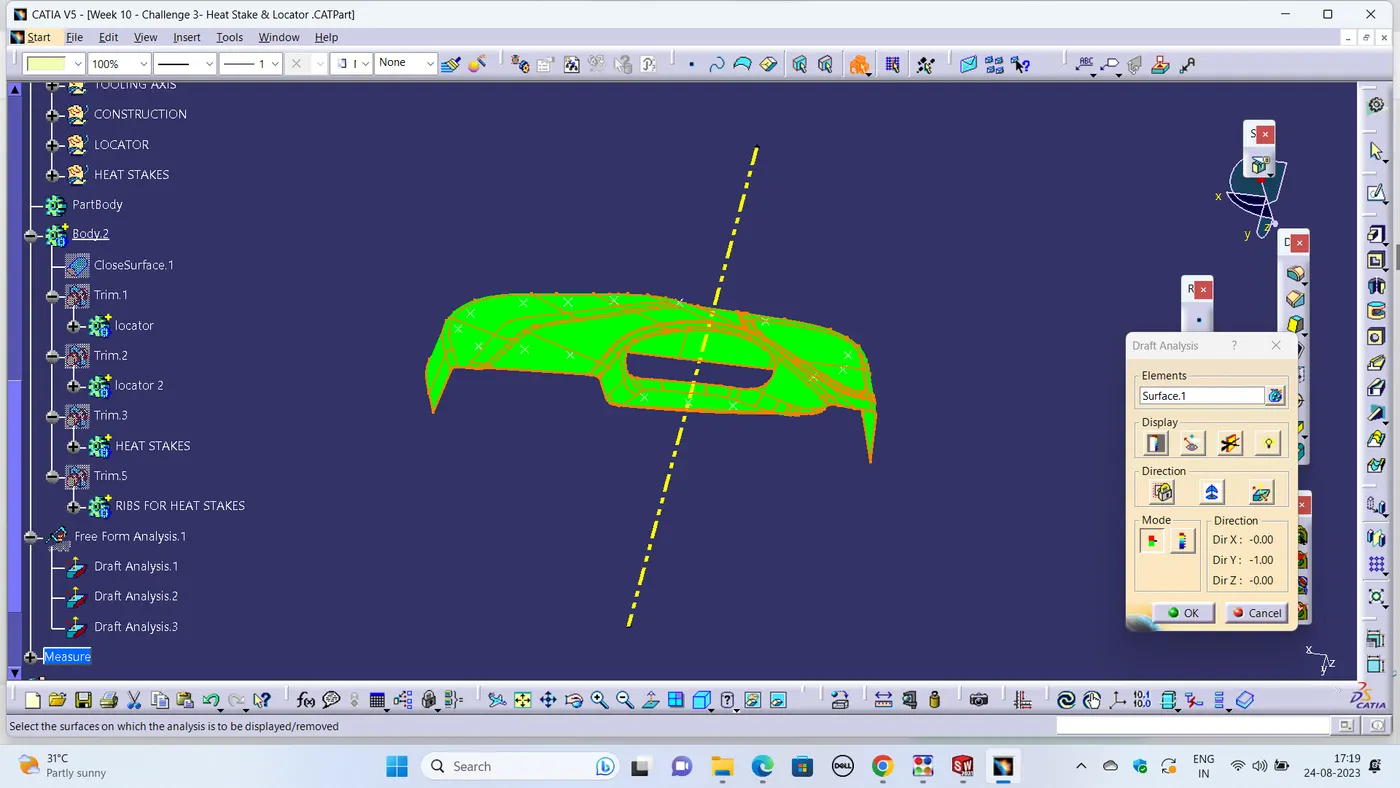
draft analysis of final product: