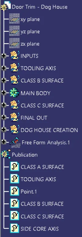
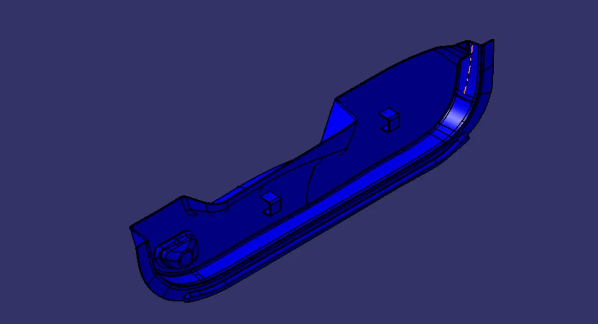
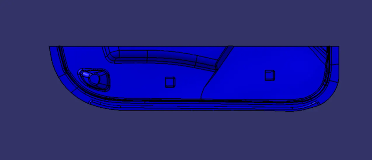
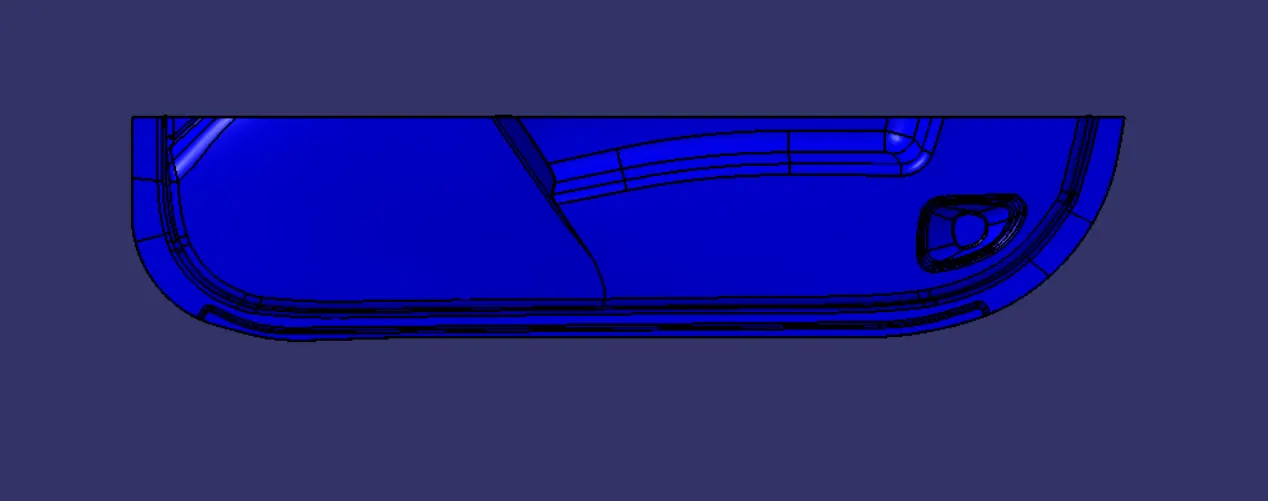
Week 10 - Challenge 2- Attachment Feature Creation (Dog House)
Draft Analysis Report:
I. Introduction:
A. Background:
Provide an overview of the project or product that requires draft analysis and tooling axis creation.
B. Purpose:
Explain the purpose of draft analysis and how it fits into the overall design and manufacturing process.
II. Draft Analysis:
A. Definition of Draft:
Define what draft is in the context of design and manufacturing. Explain its importance in various industries.
B. Methodology:
Detail the methods used for draft analysis, whether manual or computer-aided, and the tools employed in the process.
C. Analysis Results:
Present the findings of the draft analysis, highlighting any areas of concern or improvement. Include visual representations such as charts or diagrams if applicable.
D. Recommendations:
Provide recommendations for adjustments or modifications based on the draft analysis results. Discuss how these changes will enhance the manufacturing process.
III. Tooling Axis Creation Report:
A. Definition of Tooling Axis:
Explain what tooling axis is and its significance in the context of manufacturing and machining.
B. Tooling Axis Determination:
Detail the process of determining the optimal tooling axis, taking into consideration factors such as material properties, part geometry, and manufacturing constraints.
C. Tooling Axis Creation:
Explain the steps involved in creating the tooling axis, whether through manual programming or utilizing specialized software.
D. Validation:
Discuss the validation process for the chosen tooling axis. Include any simulations or tests conducted to ensure accuracy and efficiency.
IV. Integration of Draft Analysis and Tooling Axis Creation:
A. Synergy:
Examine how the results of draft analysis influenced the decisions made in tooling axis creation.
B. Efficiency Gains:
Highlight any efficiency gains or cost savings achieved by integrating draft analysis and tooling axis creation.
V. Conclusion:
A. Summary:
Summarize the key findings and outcomes of both the draft analysis and tooling axis creation processes.
B. Future Considerations:
Discuss any potential future improvements or refinements to the draft analysis and tooling axis creation procedures.
VI. Appendices:
Include any supplementary materials, such as detailed charts, graphs, or additional technical information.
Certainly, let's delve into the specifics of the Bisecting method for creating a tooling axis.
Tooling Axis Creation Using the Bisecting Method:
I. Introduction:
A. Overview:
The Bisecting method is a technique used in manufacturing and machining to determine an optimal tooling axis for a given part. This method involves finding the bisector of an angle formed by two intersecting planes on the part's geometry.
II. Steps in the Bisecting Method:
A. Identify Intersection Planes:
Identify the two planes on the part's geometry where the tooling axis needs to be determined. These planes are often defined by the part's design or manufacturing requirements.
B. Define Intersection Line:
Find the intersection line between the two identified planes. This line serves as the initial reference for determining the tooling axis.
C. Establish the Bisector:
Once the intersection line is determined, calculate the bisector of the angle formed by the two planes. The bisector is the line that splits the angle into two equal parts.
D. Tooling Axis Alignment:
Align the tooling axis along the calculated bisector. This alignment ensures that the cutting tool follows a path that optimally addresses the part's geometry and minimizes any potential issues such as excessive material removal or tool wear.
III. Considerations:
A. Material Properties:
Consider the material properties of the part, as different materials may require adjustments to the tooling axis for optimal machining.
B. Part Geometry:
The complexity of the part's geometry may influence the effectiveness of the Bisecting method. In some cases, additional considerations or modifications may be necessary.
C. Machining Constraints:
Account for any machining constraints or limitations imposed by the manufacturing process. The chosen tooling axis should align with the capabilities of the machining equipment.
IV. Validation:
A. Simulation:
Validate the chosen tooling axis through simulation software to ensure that it effectively addresses the part's geometry without causing any collisions or inefficiencies.
B. Physical Testing:
Perform physical tests using prototypes or sample parts to verify the accuracy of the tooling axis. Adjustments may be needed based on the outcomes of these tests.
V. Advantages of the Bisecting Method:
A. Simplicity:
The Bisecting method is relatively straightforward and easy to implement, making it a practical choice for certain machining applications.
B. Accuracy:
When applied correctly, the Bisecting method can result in an accurate tooling axis that optimally addresses the part's geometry.
VI. Conclusion:
Summarize the key steps in the Bisecting method for tooling axis creation, emphasizing its applicability and advantages in specific manufacturing scenarios. This method, when integrated into the overall toolpath planning, contributes to efficient and precise machining processes.