Week 10 - Challenge 1- Attachment Feature Creation (Ribs & Screw Boss)
DESIGN OF RIBS AND SCREW BOSS
Ribs:
These thin-walled vertical features are often located inside a component, and can provide rigidity and strength to a part. Ribs can also support other features, such as bosses, and can be used as alignment features or standoffs.
Screw bosses:
These are used for screws or locators in assemblies, and are often exposed to stress.
Purpose:
Ribs:
· Reinforce flat areas.
· Improve rigidity and resistance to deformation.
Screw boss:
· Provide support for screws in assembly.
· Enable part alignment.
Design guidelines for Ribs:
· Draft - 0.5 degrees per side minimum
· Thickness Typically 40% wall thickness
· Height 5 x wall thickness
· Spacing 3:1-steel height / width ratio maximum
· Minimum thickness at Tip-.75mm
· Radii 0.25mm maximum
· Ribs on opposite side of wall should be offset.
· Ribs should be connected to other structural features where possible.
Design guidelines for screw boss:
· Draft - 0.5 degrees per side minimum.
· Spacing 3:1-steel height / width ratio maximum.
· Height 3 x wall thickness.
· Radii 0.25mm maximum.
· Thickness must smaller than 60% wall thickness.
Draft analysis of A class surface:
Draw a tooling axis on surface on Y direction.
Place the draft analysis compass in tooling axis.
It may show some blue indication .It shows that part must done by side core.
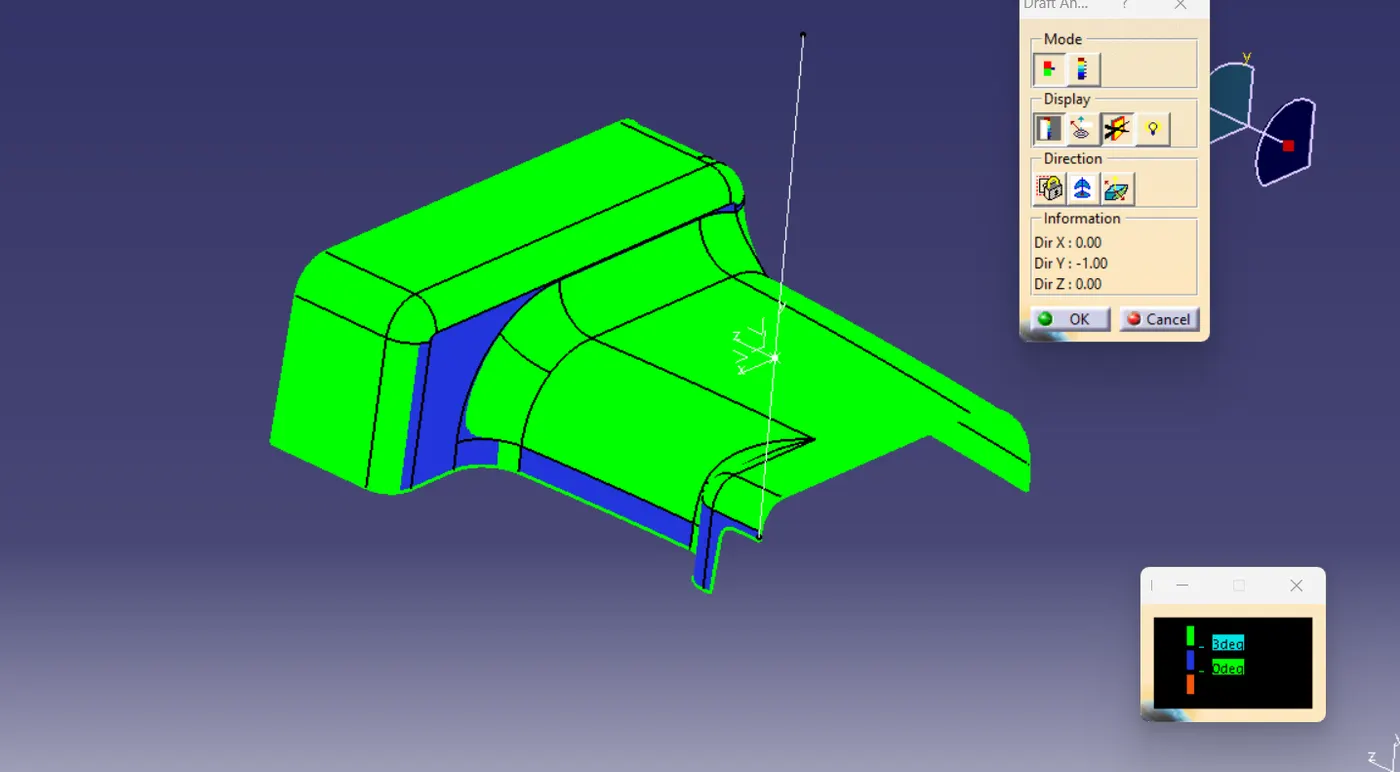
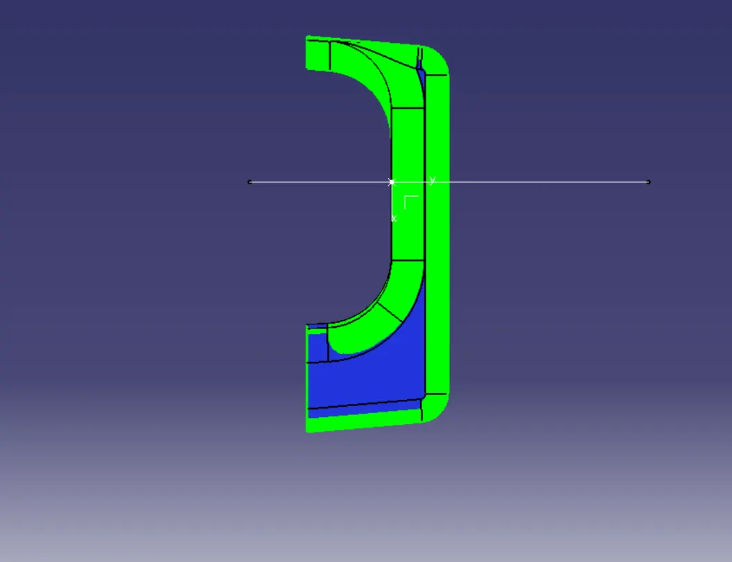
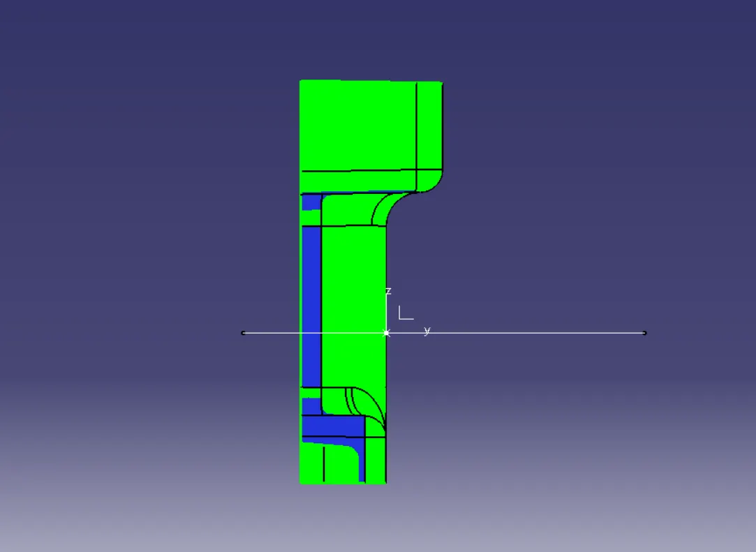
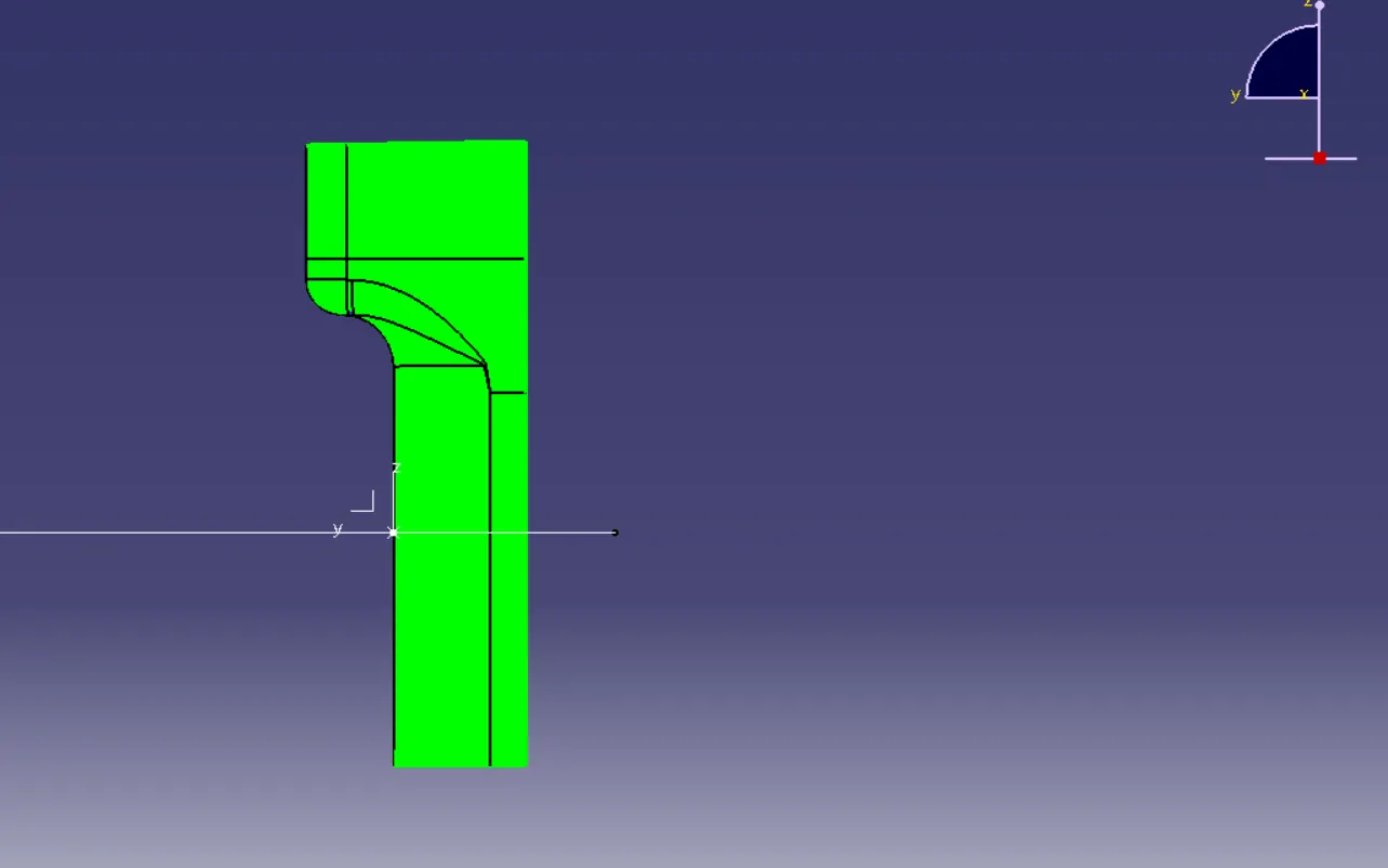
Design views of ribs and screw boss:
Specification ribs:
h=12mm
T=1mm
Radii of fillet=0.25mm
Specification screw boss:
h=7.5 mm
Dinner=5.2mm
Douter=7.5mm
Radii of fillet=0.25mm
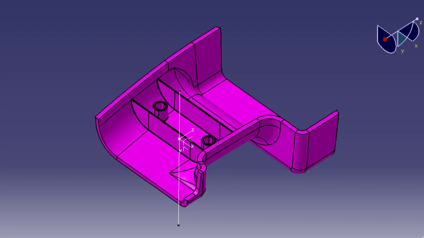
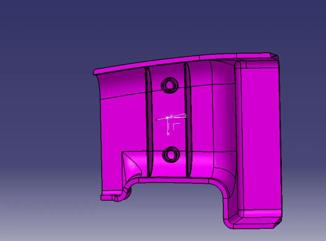
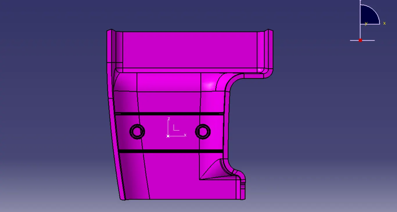
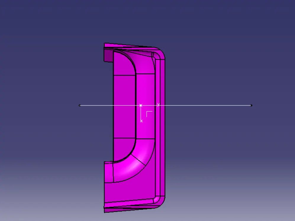
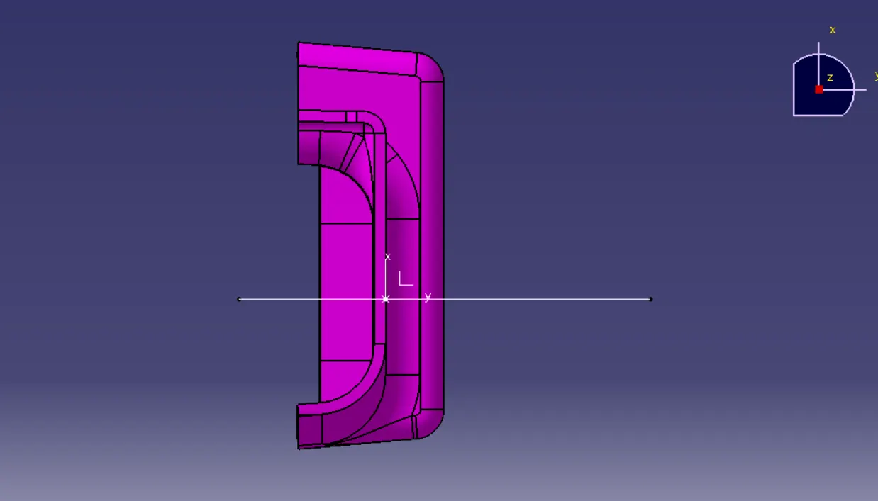
thus i have created a screw boss and ribs design.