Week 10 - Challenge 1- Attachment Feature Creation (Ribs & Screw Boss)
OBJECTIVE: To create the Door Handle Plastic Component from the given Class A Surface & then create attachment features such as Ribs and Screw Bosses for it while following the issued Design Guidelines.
STEPS FOLLOWED:
- Tooling Axis Creation.
- Draft Analysis of Class A surface.
- Creating Class B surface and Class C surface.
- Creating a Closed body of component Door Handle.
- Draft analysis for Door Handle Component.
- Creating the Sketches of Ribs & Screw Boss profile as per the given guidelines.
- Solid Profile creating for the Ribs & Screw Bosses using Thick Surface and Pad Commands. Added them to the Closed Partbody.
- Given the Draft angle and Edge Fillet Radius to the require faces as per the Guidelines.
- Check the parameters of Ribs & Screw Bosses that were is per Guidelines and standarts.
- Perform the Draft Analysis for Ribs and Screw Bosses Assembly.
Commands used Boundary, Extract, Multiextract, Trim, Join, Sweep, Point, Line, Bisection Line, Circle , Draft, Edge Fillet, Draft Analysis, Closed Body, Thick Surface, Pad, Unitrim, Remove, Intersection.
PROCEDURE TO CREATE THE MAIN TOOLING AXIS:
We'll view the Class A Surface from different axes to find out the optimal axis along which we can create our Tooling Axis:
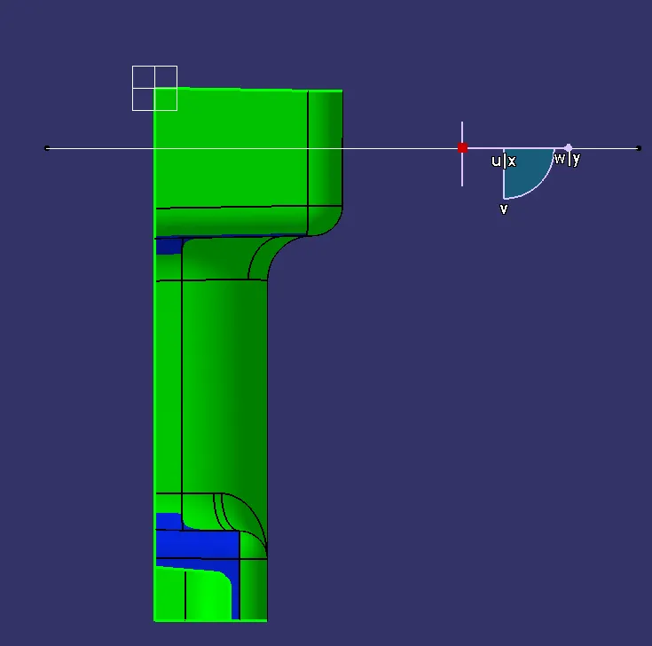
View from the X-Axis:
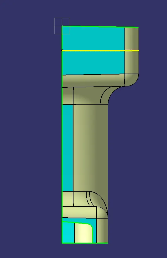
From the above image, we can see that not much surface area is exposed along this axis and hence this cannot be the direction along which we can create our Main Tooling Axis:
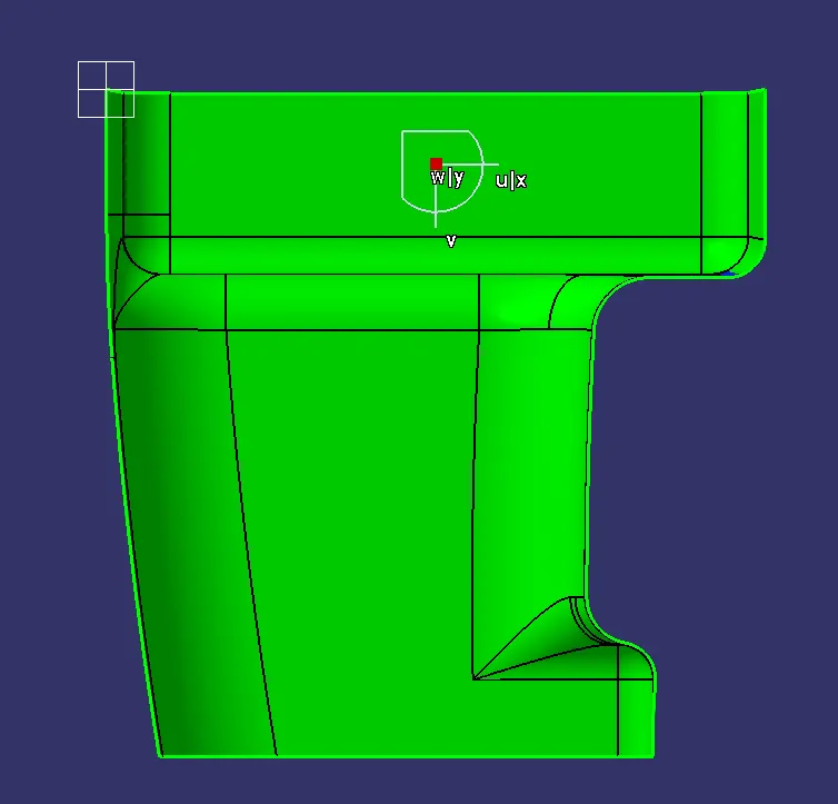
View from the Z-axis:
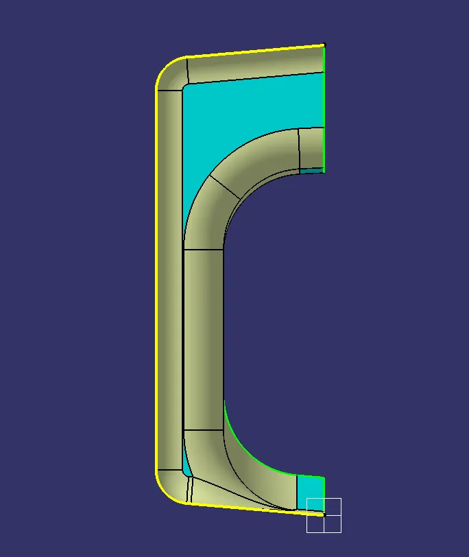
From the above image, we can see that not much area is exposed along this direction as well and hence this as well cannot be the direction along which we can create our Main Tooling Axis.
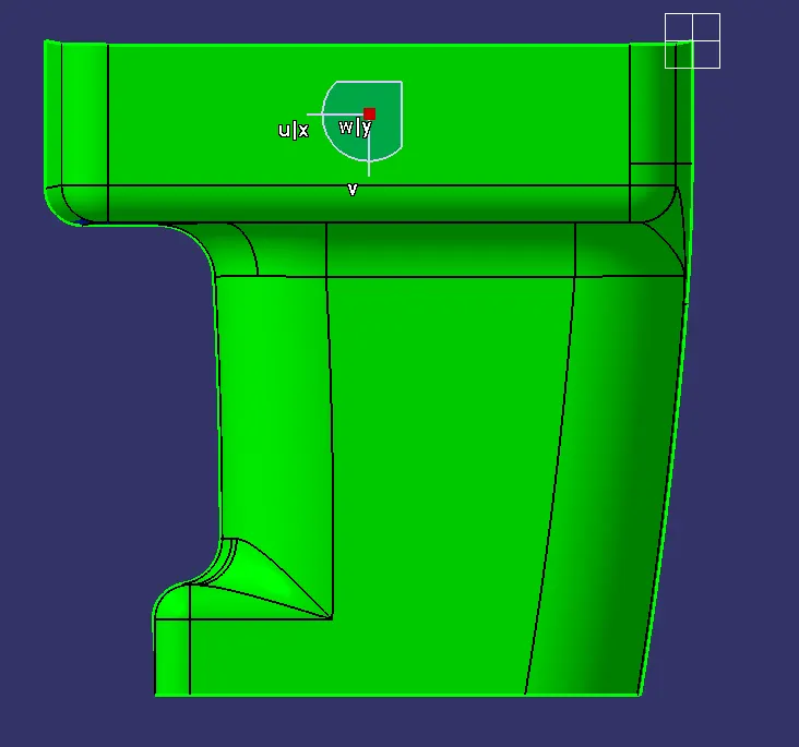
View from the Y-axis:
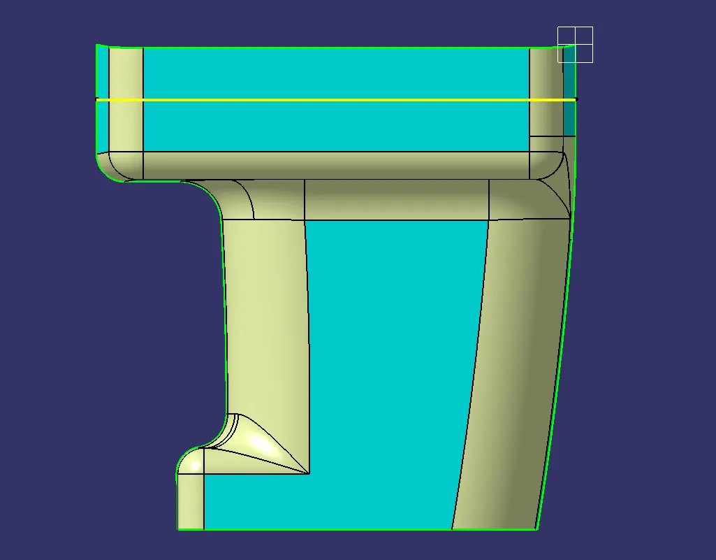
From the above image, we can see that the maximum surface area is exposed along this axis and hence we have to construct our Main Tooling Axis along this direction.
Now, we'll create a plane such that it will allow us to create an intersection as shown below using which we can create our Main Tooling Axis:
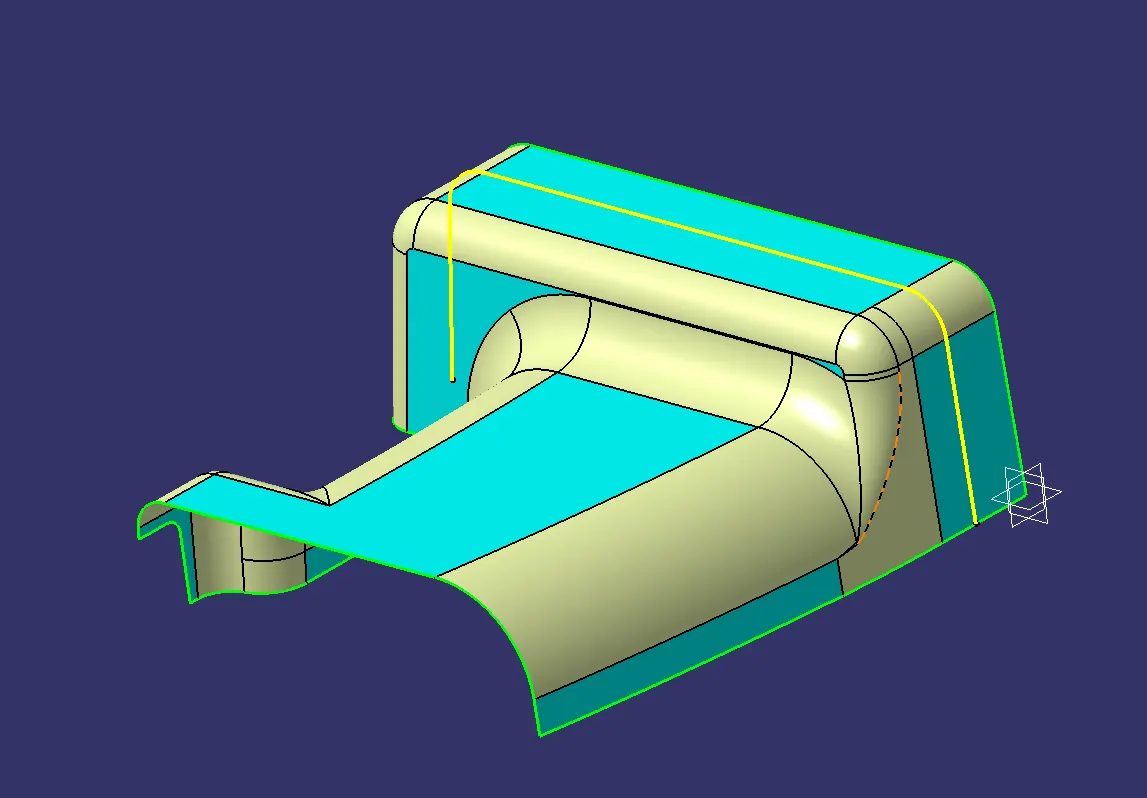
After that, we'll create two lines on the edges of the component and use those two lines to create a bisecting line as shown below:
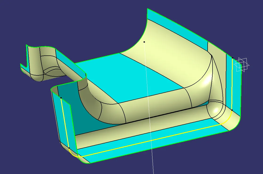
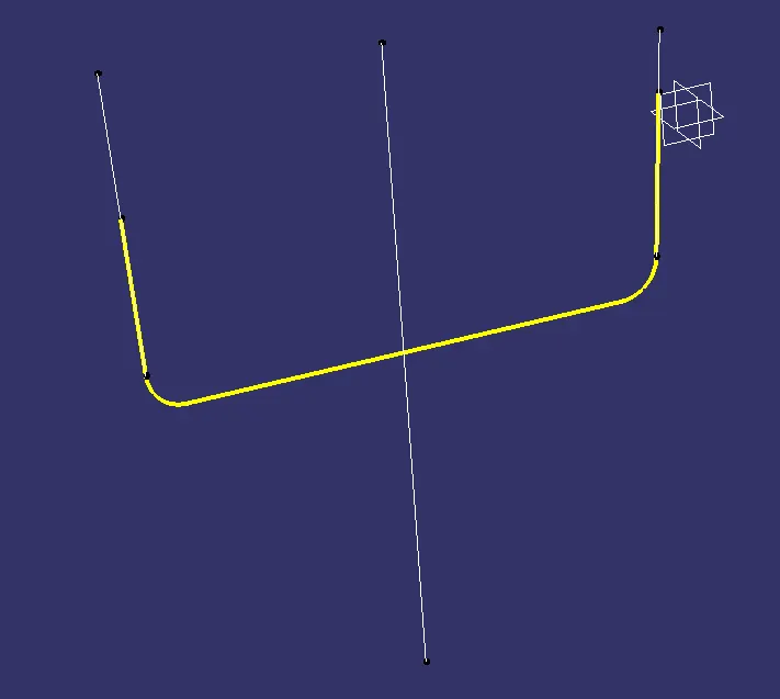
DRAFT ANALYSIS ON THE CLASS A SURFACE:
Next, We will perform a Draft Analysis on the Class A Surface itself:
Before starting with a Draft Analysis Operation, we will go to the 'Customize View Parameters' option under the 'View Toolbar'. Then we will enter the 'Customize View Mode' where we will go under the 'Mesh' option and select 'Material' and press 'OK'.
To start the Draft Analysis in the 'Generative Surface Design Workbench', we will go to 'Insert' and then look for the option called 'Analysis'. Once found, we will go under that and click on 'Feature Draft Analysis. This will open the 'Draft Analysis' Dialogue box. There, we will ensure that under 'Mode' we have selected 'Quick Analysis', under 'Display' we will select 'Show or Hide the Color Scale' and then select '3 Degrees' as the permissible draft angle. Then, under 'Direction' we will choose the icon with the symbol of the compass on it which stands for 'Use the Compass to define the new current draft direction'.
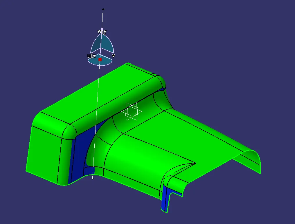
PROCEDURE TO CREATE THE CLASS B SURFACE:
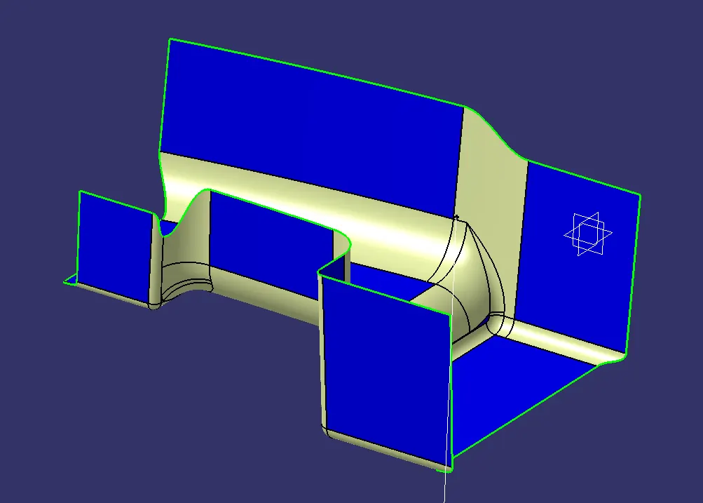
Class B surface is mostly the not visible surface and it is the back of the Class A surface.
Offset the Class A surface for 2.5mm (Thickness of Component is 2.5mm).
CREATE THE CLASS C SURFACE:
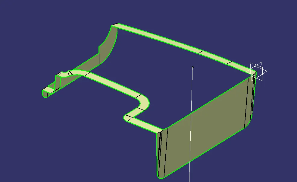
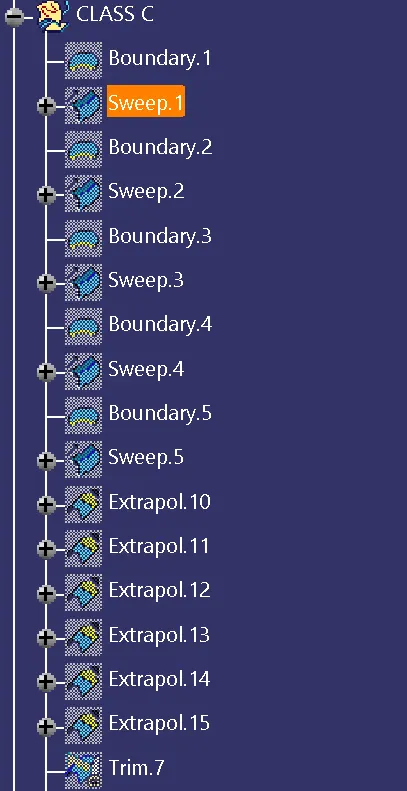
We'll use Sweep Command with Draft Direction & Reference Surface depending upon our needs and construct our Class C Surface as shown below:
Class C Surface is that connect the Class A Surface and Class B Surface.
- 1.Create a boundary on the Class A surface and then Sweep it.
- 2.By using the Sweep Command with the reference of Class A surface and angle of 87Deg to it (the 3deg will give the Draft clearence while manufacturing).
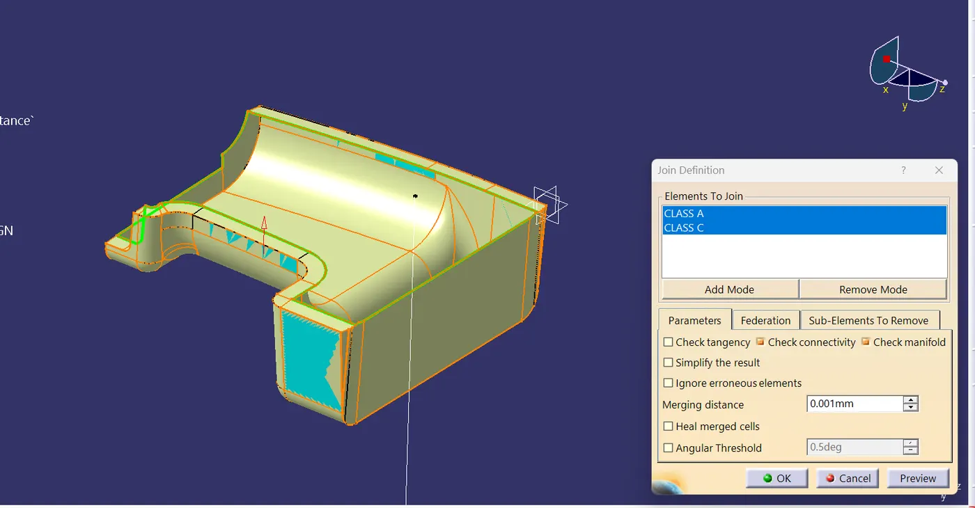
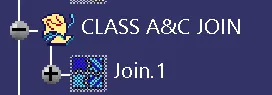
- 3.Then the Class C surface is Joined with Class A surface by using the Join Command.
- 4.The thickness or length of the Class C Surface is 8mm minimum so that it will be trimed easily with Class B surface.
- 5.Now the Joined Class A & C Surace is trimmed with the Class B surface.
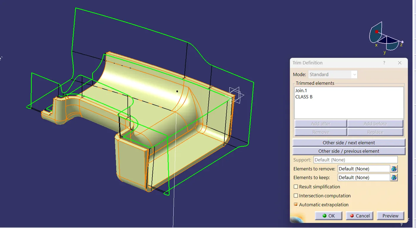
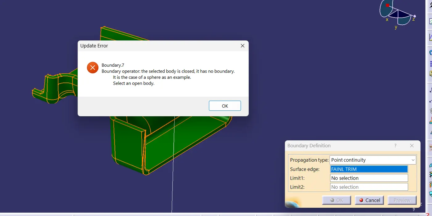
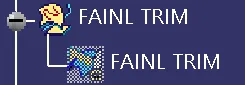
FAINL TRIM SURFACE
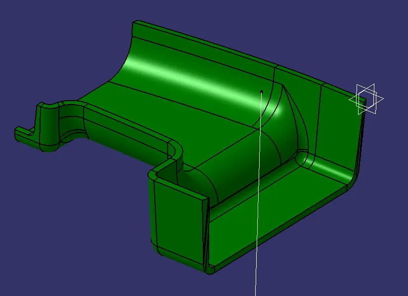
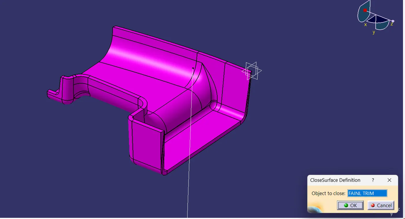
Finally, we'll go to the Part Workbench and use the Closed Surface command from the Surface-based Features Toolbar to create our solid door handle plastic component as shown below:
CREATE RIBS FOR THE DOOR HANDLE USING DESIGN RULES:
First, we'll create a point and a projection point that can be used to create a sketch as shown below:
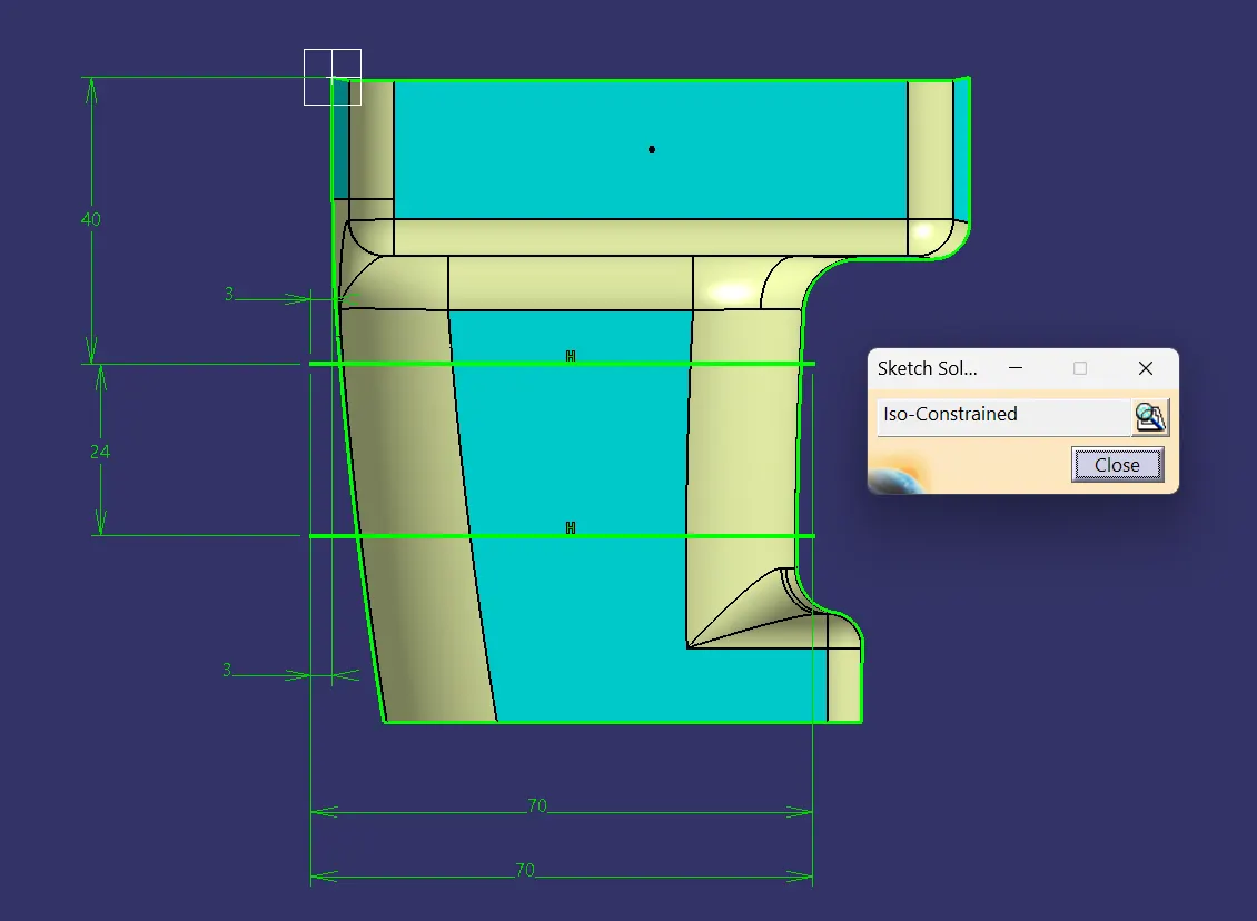
After this, we'll use the Extrude Command in the Surface Workbench to Extrude these lines for 12.5mm with respect to the Main Tooling Axis. The reason we're deciding the height as 12.5mm is that the thickness of our plastic component is 2.5mm and according to the given design rules for ribs, we can make the height of our ribs up to 5 times the value of the thickness of the component.
Hence, 2.5*5 = 12.5mm
We'll also provide a second limit of 1mm so that the extruded surface doesn't have any gaps from the surface of the component.
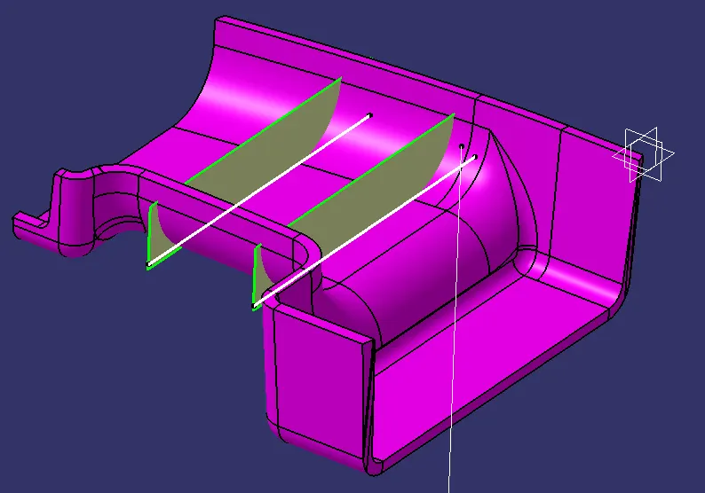
Now, we'll go to the Part Workbench and use the thicken command to make the extruded surface thick by 0.5mm on each side as shown below:
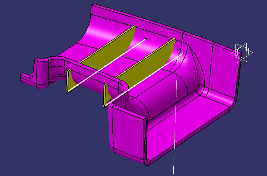
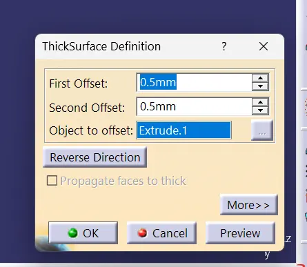
The thickness of the Rib is 1mm because according to the design rule we're supposed to create the rib with 40% thickness of the plastic component and since the thickness of our plastic component was 2.5mm hence 40% of 2.5mm is 1mm.
Now, we're going to perform a Boolean Operation known as Union Trim to get rid of sections of ribs that are protruding outside of our components shown below:
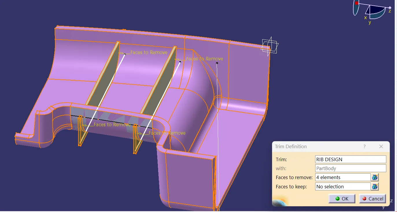
Now, we're going to provide the draft of 0.5 degrees on each side of our rib in accordance with the design rules as shown below:
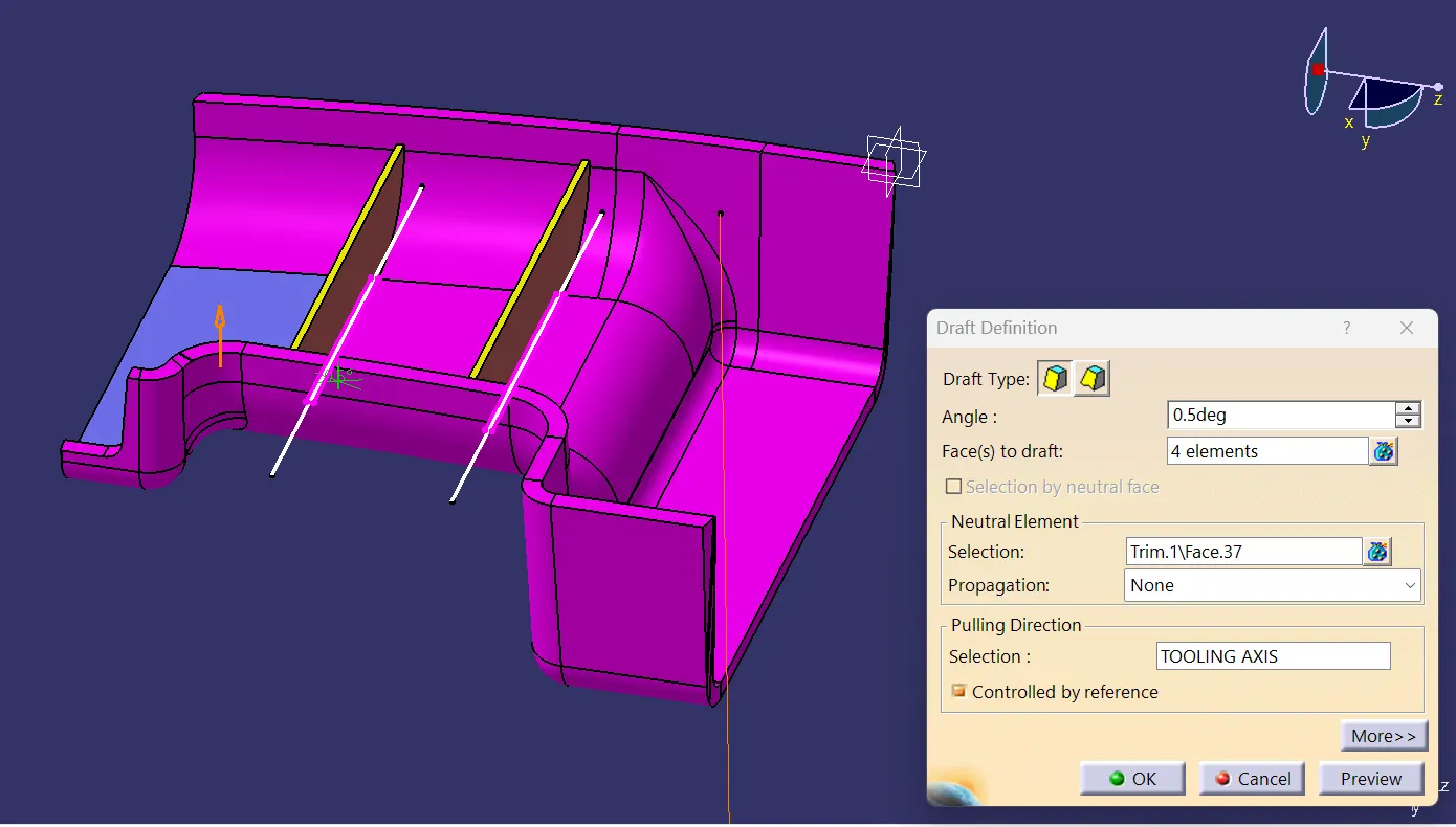
After applying the draft angle on both ribs we'll use the measure tool to measure the distance between two edges at the upper section of the rib that was supposed to be higher than 0.75mm so that molten plastic can flow in it easily to eventually fill it properly.
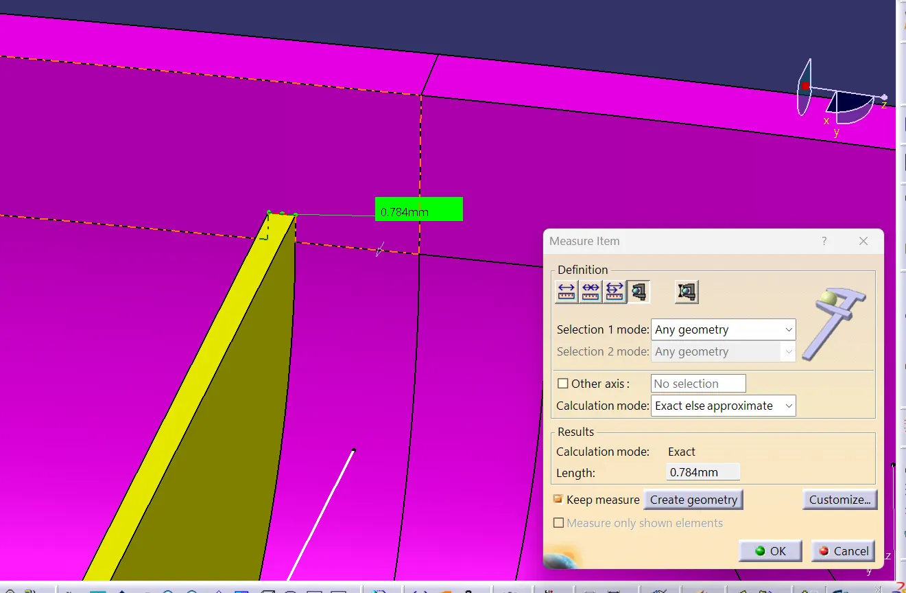
From the above image, we can see that the distance between two edges after applying the draft angle is 0.784mm which satisfies our design conditions.
Now, we'll apply the fillet values at each and every face of our ribs for a value of 0.25 according to our design rules as shown below:
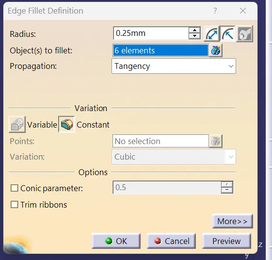
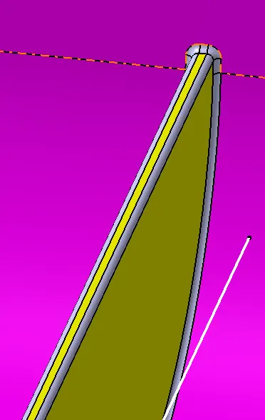
Hence our ribs are made for this component following all the necessary design rules.
RIB'S ANALYSIS VIA INTERSECTION:
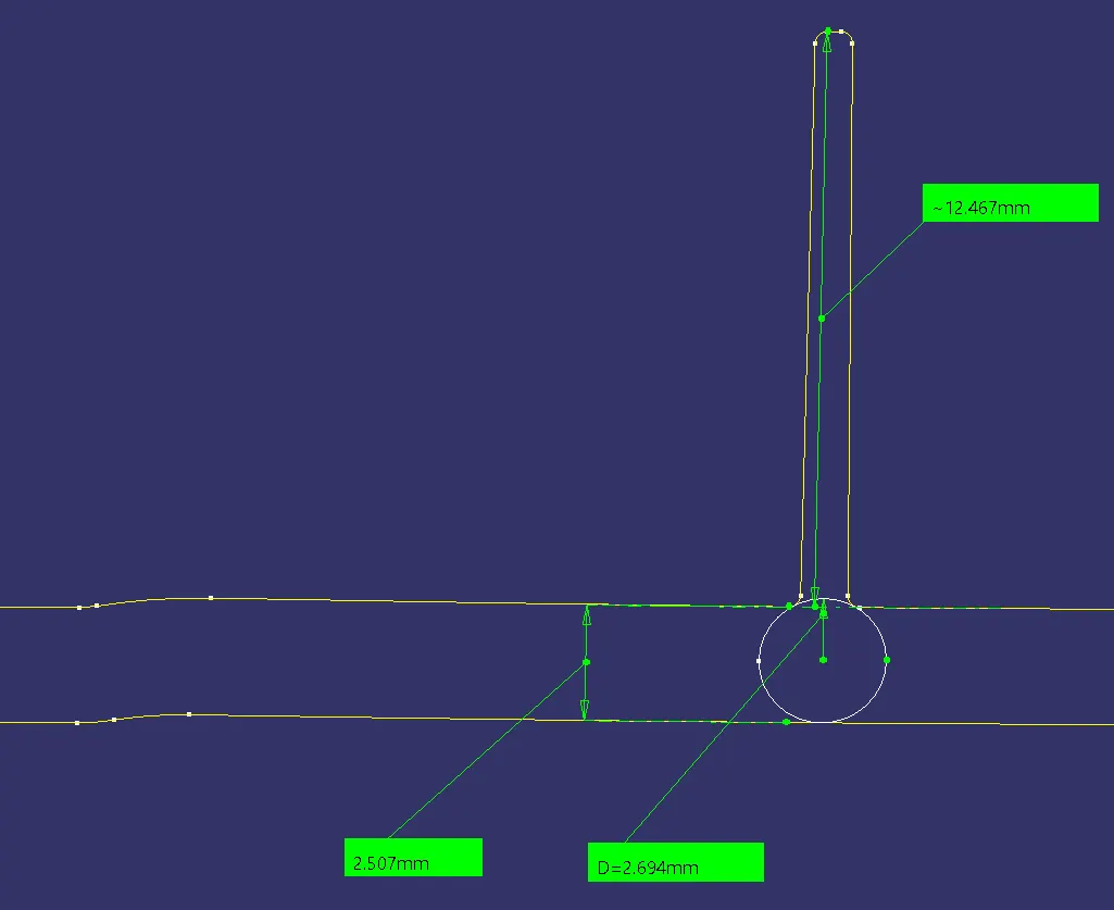
THICKNESS OF THE COMPONENT = 2.5MM
RIB'S HEIGHT=12.5MM
DRAFT ANGLE=0.5 DEGREES
RIB ROOT'S THICKNESS=2.694MM
RIB'S FILLET RADIUS=0.25MM
RIB'S THICKNESS AT THE TOP = 0.784
CREATE SCREW BOSSES FOR THE DOOR HANDLE USING DESIGN RULES:
First, we'll begin by creating the sketch for the Screw Bosses.
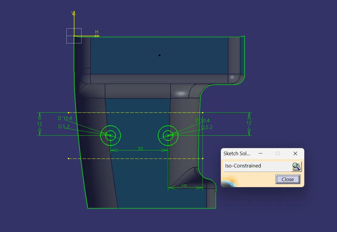
After this, we'll use the Pad Command in the Part Workbench to extrude these two bosses to a certain height.
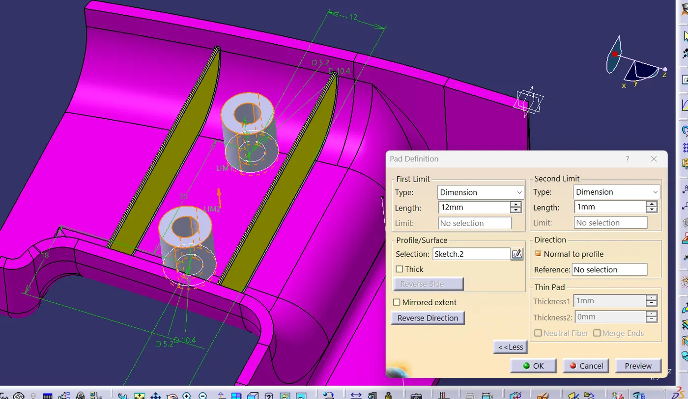
Finally, both our ribs and bosses are ready for the plastic component and using boolean operations we'll add it to the main body.
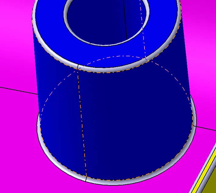
After that, we'll apply a draft angle of 0.5 degrees on both bosses according to the design rules as shown below:
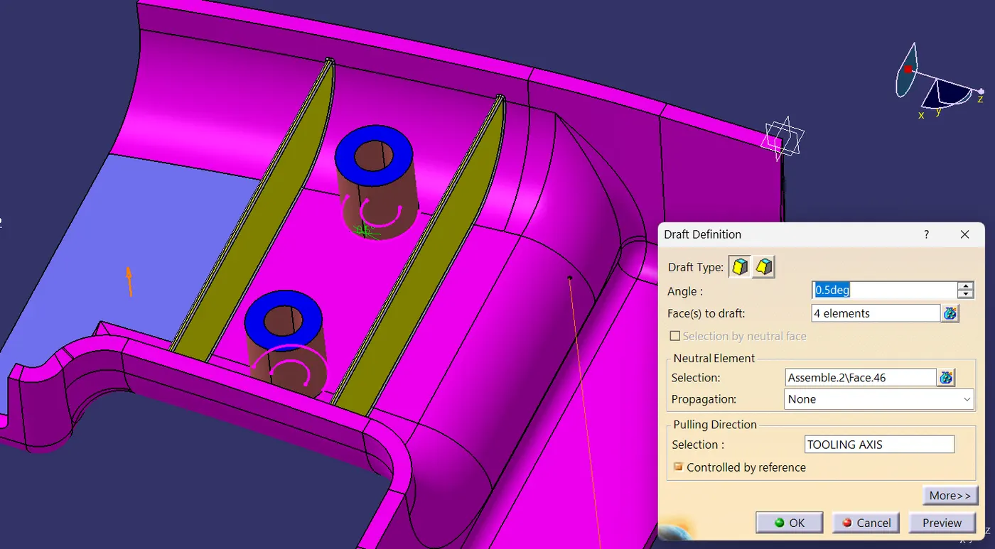
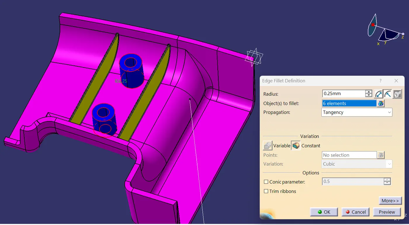
DRAFT ANALYSIS ON THE FINAL BODY:
Finally, we'll perform the Draft Analysis for the Final Part in the Part Workbench:
We'll click on the 'Draft Analysis' under the 'Analysis' Toolbar in the Part Workbench.
Then, we'll click on the Compass Symbol under 'Direction' which stands for 'Use the Compass to define the new current draft direction'.
We'll drag and place the compass on the Main Tooling-Axis.
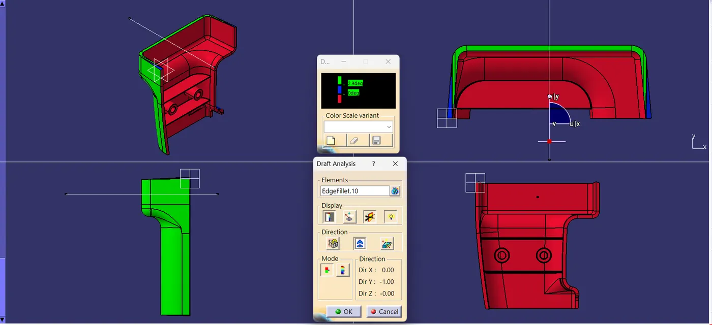
Then, we'll select 'Show or Hide the Color Scale' under 'Display' and define our Draft-Angle as 3-Degrees. After that, we'll click on the surface of the Final Part to show the results as shown below:
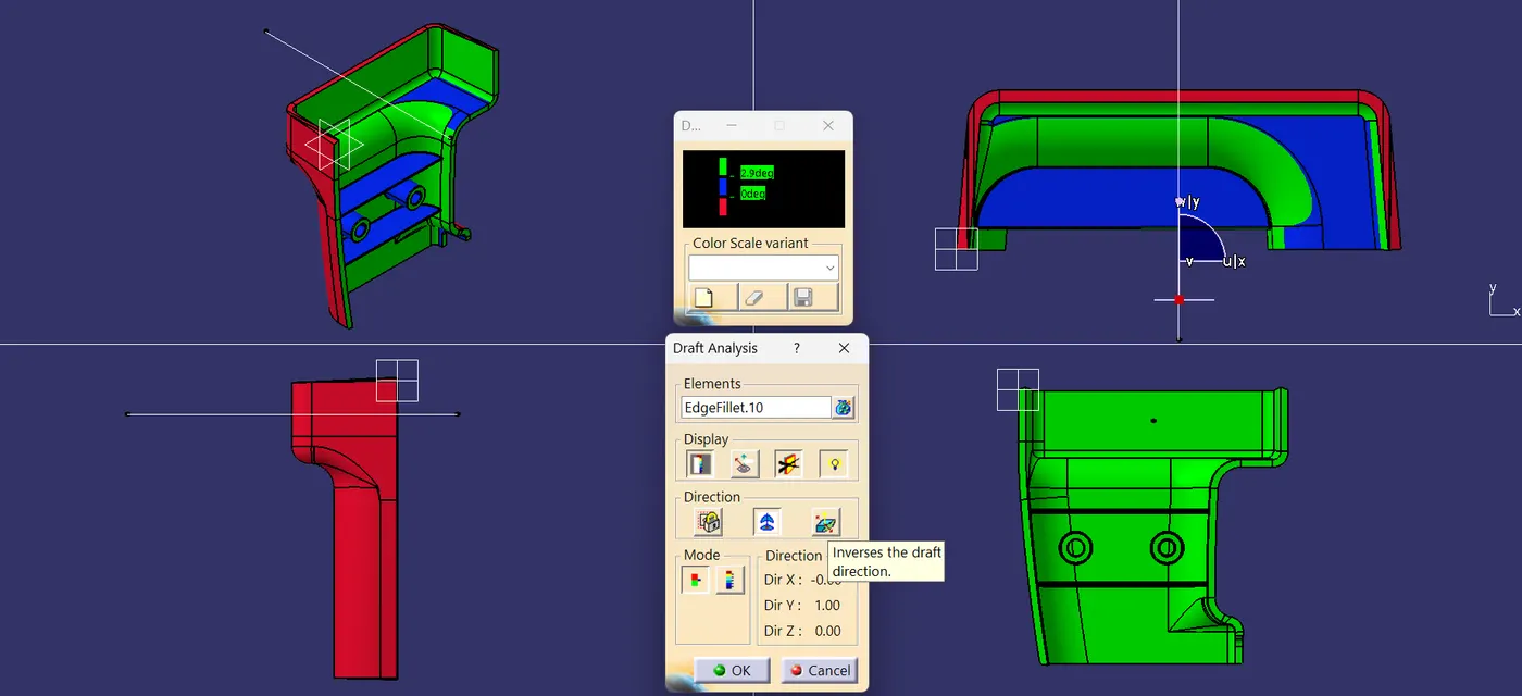
In the Draft-Analysis,
Green Colour stands for regions where the Draft Angle is more than 3 degrees,
Blue Colour stands for regions where the Draft-Angle is between 0-3 degrees, &
Red Colour stands for regions where the Draft Angle is lower than 0 degrees
OUTER DIRECTION
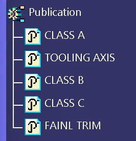
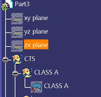
TREE STRUCTURE:
1. CLASS A SURFACE:
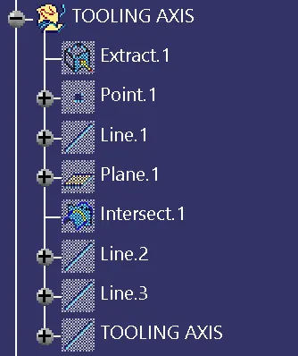
2. MAIN TOOLING AXIS:
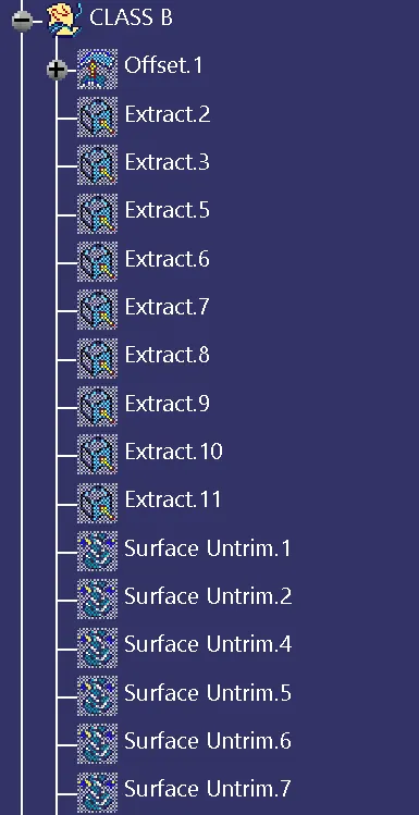
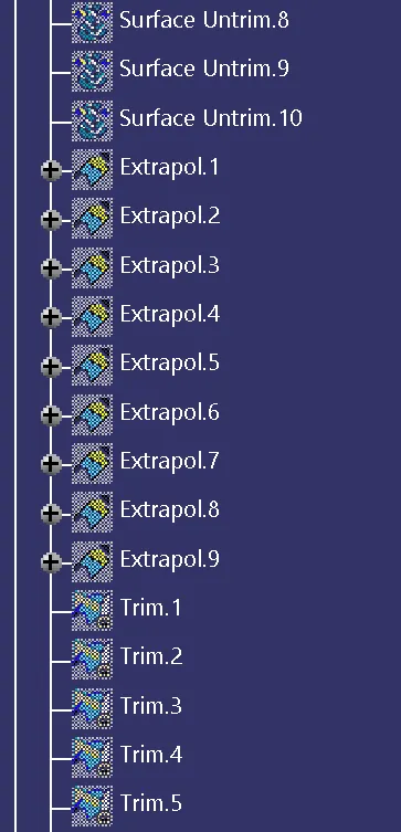
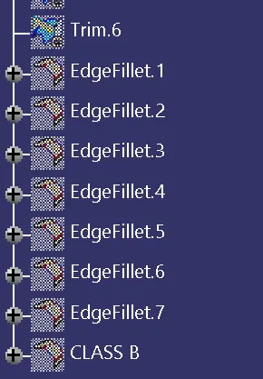
3. CLASS B SURFACE:
4. CLASS C SURFACE:
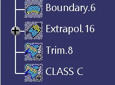
CLASS A&C JOIN.
FAINL TRIM.
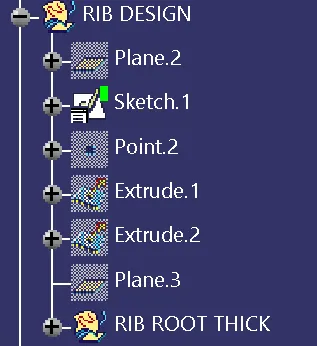
RIB DESIGN.
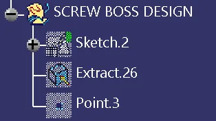
SCREW BOSS DESIGN
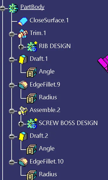
PART BODY.
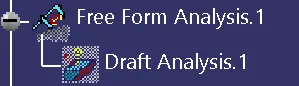
DRAFT AMALYSIS.
PIBLICATION