Week 1 Stress Concentration on a Plate with hole
AIM :
To design a Structural steel Plate with single & Multiple hole, determine maximum Stress concentration developed & Total Deformation on both designs.
OBJECTIVES :
To design a Plate with single hole as per given dimensions by using ANSYS Spaceclaim.
To design a Plate with Multiple hole as per given dimensions by using ANSYS Spaceclaim.
Providing Boundary condition as fixed support to the left end on the both design.
Providing Boundary condition as External Force to the Right end on the both design.
Comparing Stress and Strain Variation on both designs.
INTRODUCTION :
If any component have same cross sectional area throughout the component, by results simple stress will be distribute as long as.
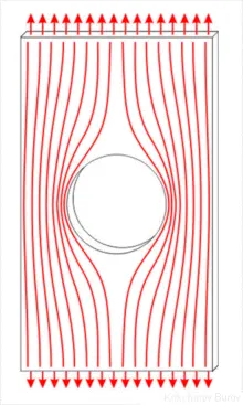
A Stress concentration is also called a stress raiser or stress riser, it happens at where cross section of the component has lesser is significantly to surrounding region. Whenever a machine component changes the shape of its cross section, the simple stress distribution no longer holds good, because neighbourhood of the area have some discontinuity in the same component due to that cause some interruption to the flow of stress. This irregularity in the stress distribution caused by abrupt changes of form is called stress concentration. It occurs for all kinds of stresses in the presence of fillets, notches, grooves, holes, keyways, splines, surface roughness or scratches etc.
PROCEDURE FOR ATTAINING THE OBJECTIVES :
I) CAD MODEL :
By Using ANSYS Spaceclaim, we design a model for Structural Analysis.
Case 1 :
Open a Space Claim, we have to design a model with single hole based on given dimensions which are sort out below,
Length of the component = 300 mm
Height of the component = 120 mm
Thickness of the component = 30 mm
Diameter of the hole = 60 mm
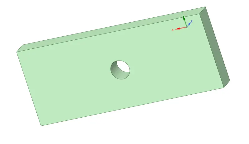
After creating the Design with single hole, it's shown as above image.
Case 2 :
Simialrly, we have to design a another model, but this time we have to make a addition hole as per given dimensions which are sorted out below,
Diameter of smaller hole = 30 mm
Distance between at bigger & smaller hole mid point is 90 mm.
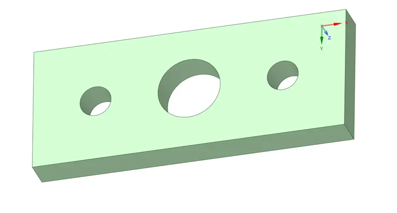
After creating the Design with multiple holes, it's shown as above image.
II) Mechanical Model:
First of all, open the Mechanical Model, make sure keep material as Structural Steel for both model and then going to discritization the model.
i) Discritization :
Basically, To divide the entire model into infinitesimal control volume, that frame work is called Meshing. This process is called Discritization. This FEM is widely used for solving partial differential equation in different physical field such as Structural problem, Heat transfer problem, Fluid flow problem, Electro magnetic Analysis & Acoustics Analysis.
Case 1 :
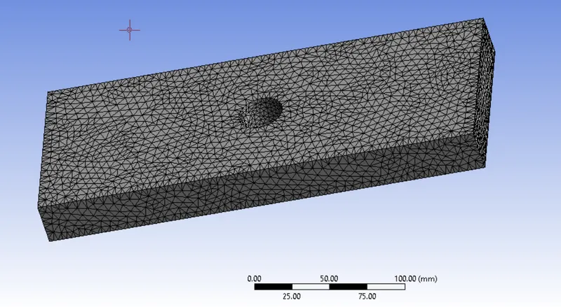
Element Size = 3 mm
Element Type = Volumetric Meshing with Tetrahedrons or Tetrahedral by using Patch Conforming Algorithms
No of Nodes = 33651
No of Elements = 18985
We keep "Use Global Settings" for Element Order, so Ansys generated second order elements, each tetra elements have 10 nodes itself. By results, it take more time for solving as compared to First order elements & increasing storage space also. But, results has more accurate as compared to first order discritization.
After done the meshing on the model, it has looks as shown in below image.
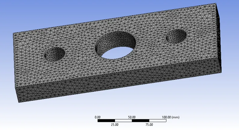
Case 2 :
Element Size = 3 mm
Element Type = Volumetric Meshing with Tetrahedrons or Tetrahedral by using Patch Conforming Algorithms
No of Nodes = 38316
No of Elements = 21461
We keep "Use Global Setting" for Element Order, so Ansys generated second order elements, each tetra elements have 10 nodes itself. By results, it take more time for solving as compared to First order elements & increasing storage space also. But, results has more accurate as compared to first order discritization.
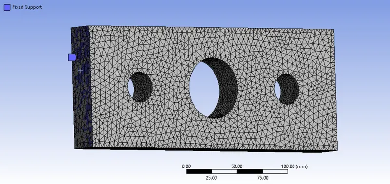
After done the meshing on the model, it has looks as shown in below image.
Boundary Conditions :
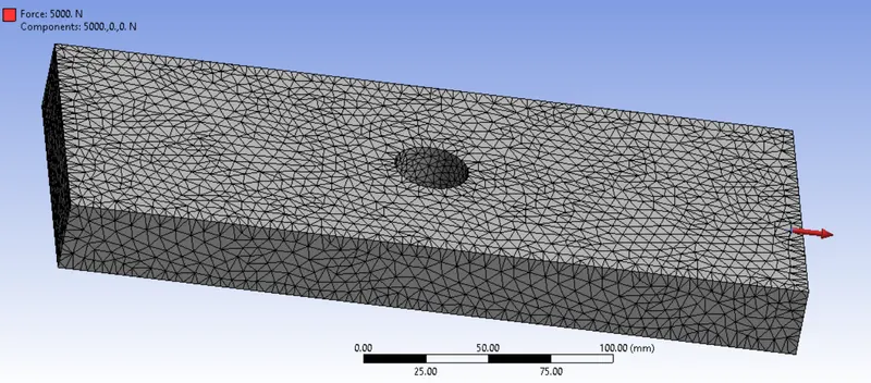
Case 1 :
Applied Force :
Apply a Force on a right end with 5000 N tensile load acting on it.
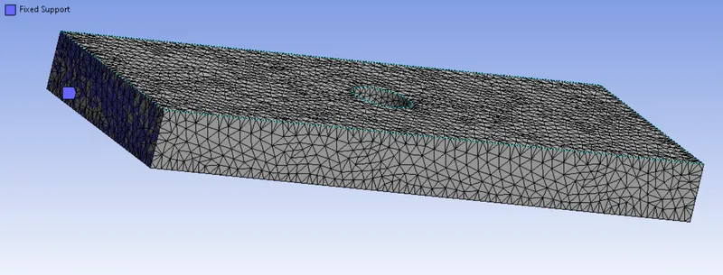
Fixed Support :
Fix the left end as a fixed support. While performing a simulation, it shouldn't tends to move.
Case 2 :
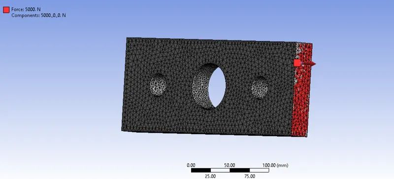
Applied Force :
Similarly, Apply a Force on a right end with 5000 N tensile load acting on it.
Fixed Support :
Fix the left end as a fixed support. While performing a simulation, it shouldn't tends to move.
RESULTS :
Contour for Deformations :
Case 1 :
Case 2 :
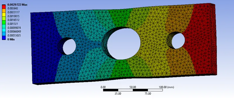
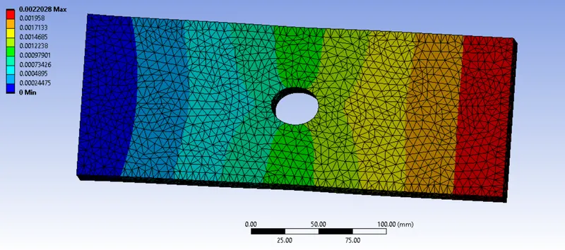
As we can see from the deformation contour plots, the deformation for multiple holes component has more deform occurs as compared to Single hole component in both lateral & Longitudinal directional.
Maximum deformation for single hole model is 0.00220 mm and for multiple hole model is 0.002972 mm.
Mass of material quantity is lesser in case 2, by results resistance of deformation also be lesser as compared to case 1.
For component, it should resist the deformation when we apply permissible load. In this two case, case 1 is better than as case 2 based on deformation of a component.
Contour Plot for Stress :
Case 1 :
Case 2 :
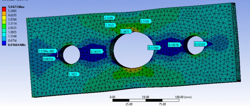
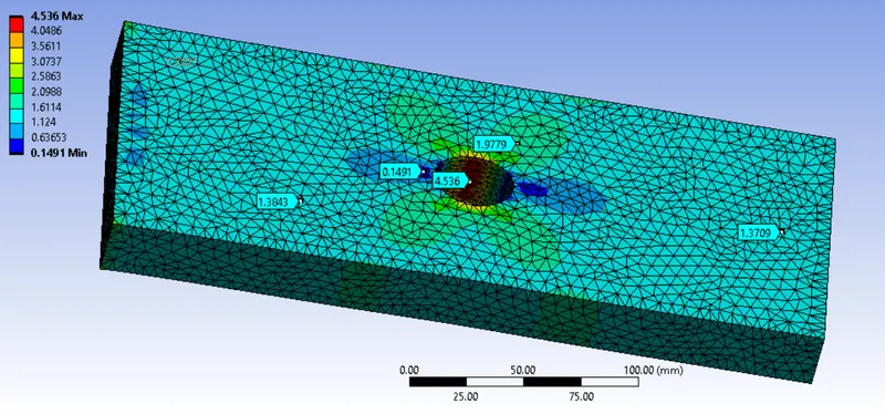
More stress is developed at multiple holes component, because while deformating a component, a cross sectional area might be decreased. Due to decreasing the cross section of the component at anywhere with the same magnitude of applied force, by result stresses will increased at the place of less cross sectional area.
Due to presents of multiple holes at middle of the components in case 2, more resistance has created at top & bottom portion of the model as compared to case 1. If we take case 1, stress concentration acting over of the hole at top & bottom portion is less as compared to case 2..
In case 1, maximum stress is 4.536 Mpa at where top & bottom tip of the hole and Minimum stress is 0.1491 Mpa at where left & right tip of the hole.
In case 2, maximum stress is 5.9473 Mpa at where top & bottom tip of the hole and Minimum stress is 0.01664 Mpa at where left & right tip of the hole.
CONCLUSION :
Analysis stand point :
Basically, product engineers are preferring a component have to less internal stress. Case 1 have less stress developed and also less stress concentration on it due to curved surface.
So we perferred Case 1 as analysis stand point of view.
Manufacturing stand point :
Generally, holes are made for material reduction techniques. If we made a sheet plate without any hole, by results material cost will increased. Inorder to reduce the cost of the material, we made hole at where optimum location, also make sure we have to consider stress concentration of a component.
In case 2, material cost has been decreased while manufacturing a component with multiple holes. But, life of the product & strength of the product has decreased due to large deformations & high stress concentration on top & bottom of the hole.
Inorder to manufacturing an good strength component, go with single hole model. It little more higher material cost as compared to case 2 model, but we get a good strength component, low deformations & good product life cycle.
As a manufacturing point of view, I perfer Case 1 model.