Stress Concentration on a Plate with hole
AIM
1) Create a plate of thickness 300 mm length and 120 mm width and 30 mm thickness.Also the plate will be having a circlular hole of dimension 30 mm at the centre.
2) In the first case we need to create an extra pair of holes of dimensions 30 mm diameter, at 90 mm part from the center of the first hole.
OBJECTIVE
In the both cases we fix one face of the plate at one end and we apply a 500 N force on the other side of the plate.Then we do a static structural analysis on each of these plates and we extract the total maximum deformation and maximum stress devoloped in each of these plates.And we need to decide which plate is to be selected from analysis and manufacturing point of view.
PROCEDURE
First we need to design the plate for both the cases.First set the static analysis in the workbench by drag and drop the static analysis into the program schematic area. Then in the geometry area, as we click there this will directs to open the SpaceClaim.In the spaceclaim with the use of rectangle tool we can draw the rectangle of given dimensions and with the use of circle option we can draw the circular hole and using the Pull option we can add thickness to the plate .
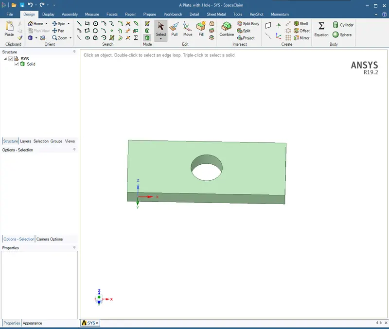
Plate with Single Hole
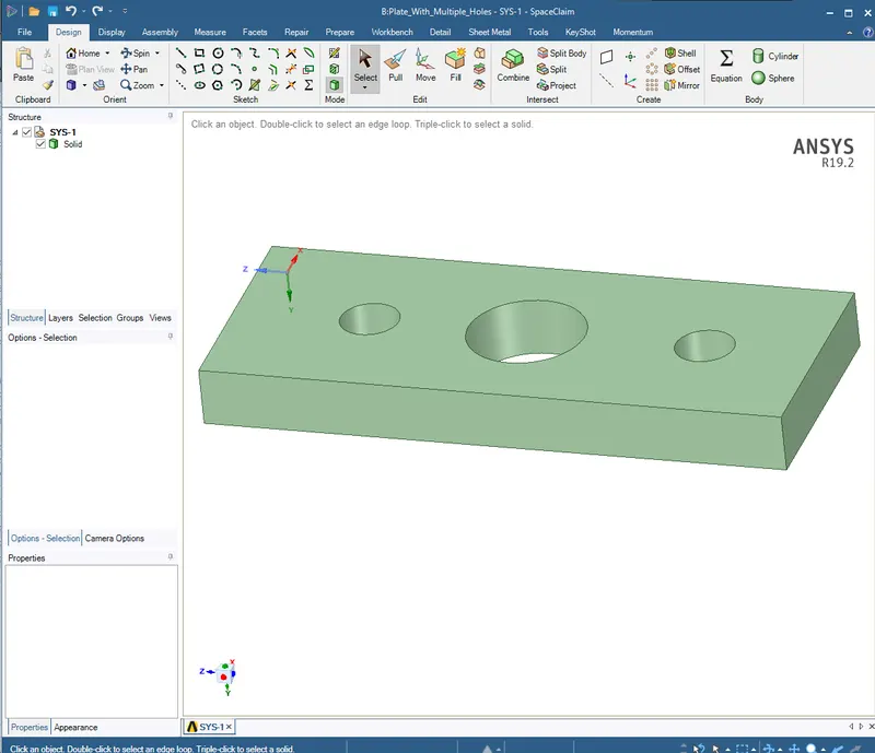
Plate with Multiple Holes
Then we need to Open the ANSYS Mechanical Modeller , we need to set up the analysis.For that first we need to discretize the model by meshing it.We need to mesh the model with the tetrahedral mesh as this is a 3D model.For that in the mesh we need to insert a method and select the geomerty in it and set the method as tetrahedrons.Then generate Mesh.
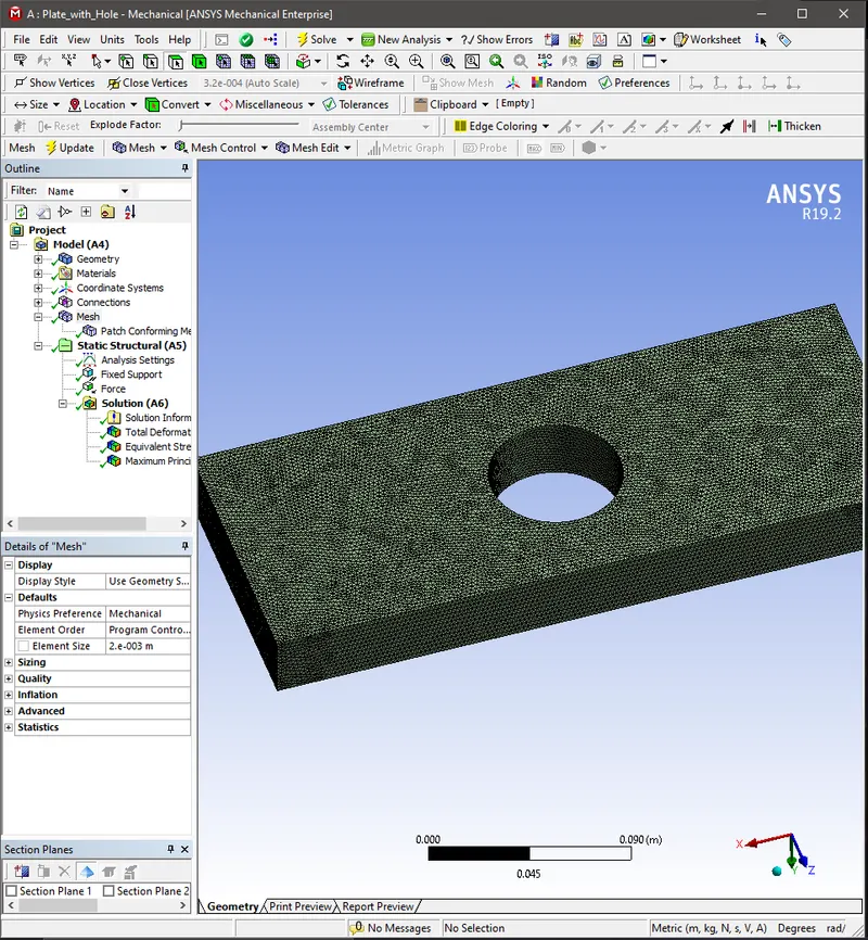
Tetrahedral Meshed Hole with Single Hole
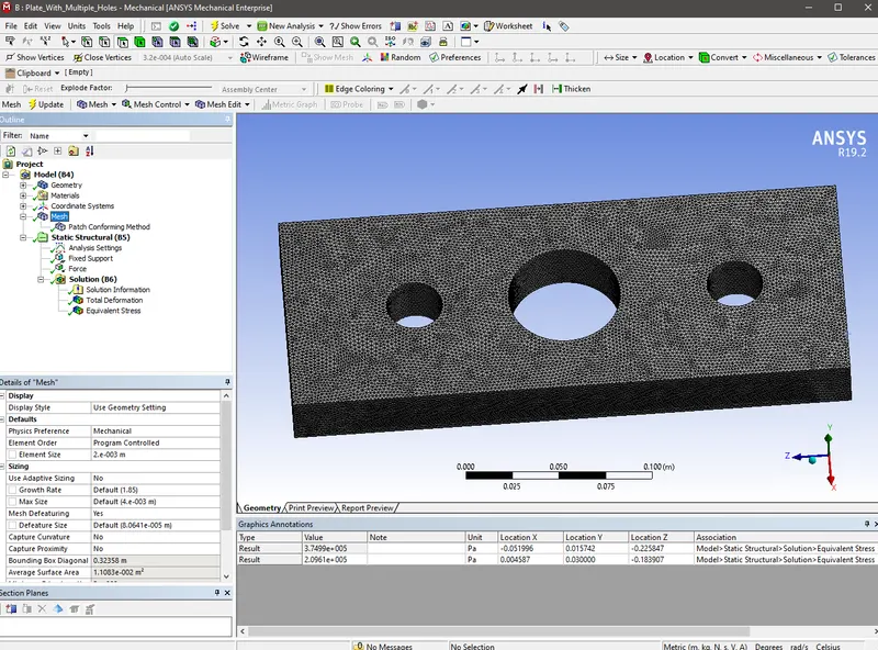
Tetrahedral Meshed Hole with Multiple Holes
Then in the Static structural area we need to add fix support and select one face of the plate thickness and on the other side we need to add force of 500N in Components mode as this will let us to apply the force in the right direction.
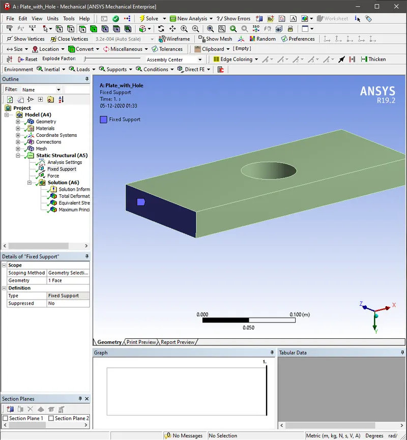
Fixed Support Created
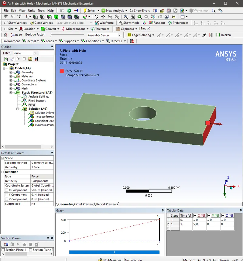
Force Appllied
Then in Solution Information we need to add total deformation and Von Mises Stress in it as we need to find out the maximum deformation and maximum stress devoloped in each of these cases.And then Pressing F5 or Select solve.
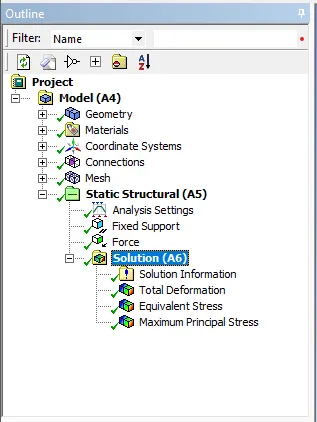
Solutions requested
RESULTS
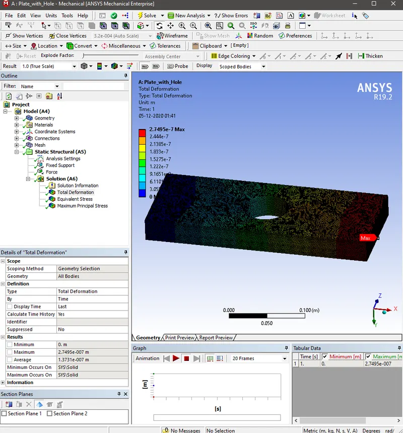
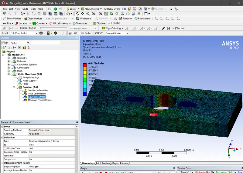
Equivalent stress devoloped in the plate with Single Hole
Total Deformation devoloped in the plate with Single Hole
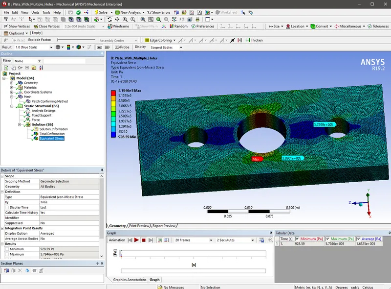
Equivalent stress devoloped in the plate with Multiple Holes
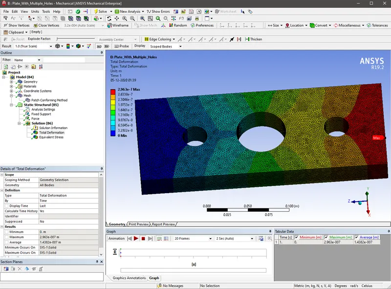
Total Deformation devoloped in the plate with Multiple Holes
We can see that the maximum stress devoloped in the plate with single hole is about 6.047e^5 Pa while in case of plate with Multiple Holes , maximum stress of 5.7946 e^5 Pa .These maximum Stress occurs at the hole region as the stress concentration happens at these geometrical features like holes.As the cross sectional reduced due to the hole, the stress will increased.When the forced increased the cup and cone fracture will occurs and the tearing of the plate will happens,
Similarly Total Deformation happens in the first case is 2.7495e^-7 and in the second case it is 2.963e^-7.So in the first case the deformation happens is less compared to the other plate.
Since the deformation in case of first plate is less than the second plate, in an analysis point of view I would select the first plate eventhough the stress devoloped in second plate is small.For small stress itself the deformation happens is more.So failure will happens earlier than the first plate.
But in case of the manufacturing point of view, the easiness of manufacturing , which is manufacturability is considered.So plate with one hole is easy to manufacture .So first plate will be selected as manufacturing point of view.We need to program for another set of code for tool movement for making the other pair of holes.If this movement can be avoided we can make the plate in cost efficiently.
CONCLUSION
The process of setting up the deck for static structural analysis in the ANSYS Workbench is learned and we post process the results of the simulation also.