Week 1 Stress Concentration on a Plate with hole
Geometry
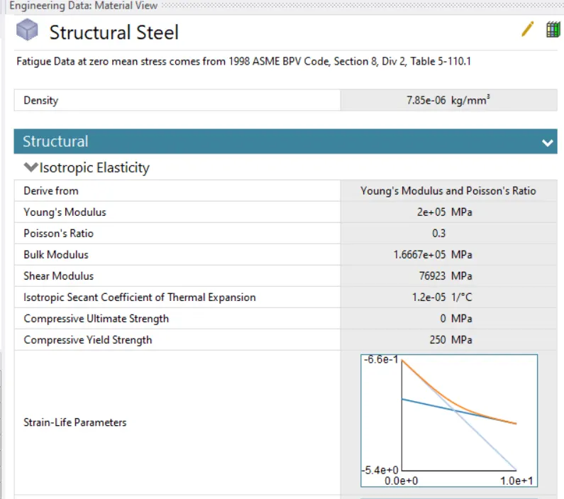
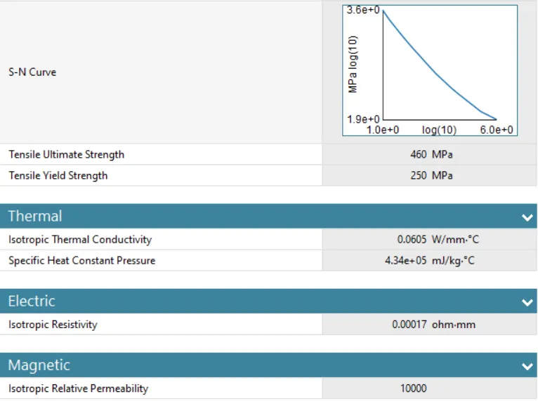
For the given challenge, the plate with a single hole is taken as Case 1 while the plate with multiple holes is taken as Case 2. The material was selected from Engineering Data Sources. The material used for both the cases of this challenge is Structural Steel. The details and specifications of this material are given below.
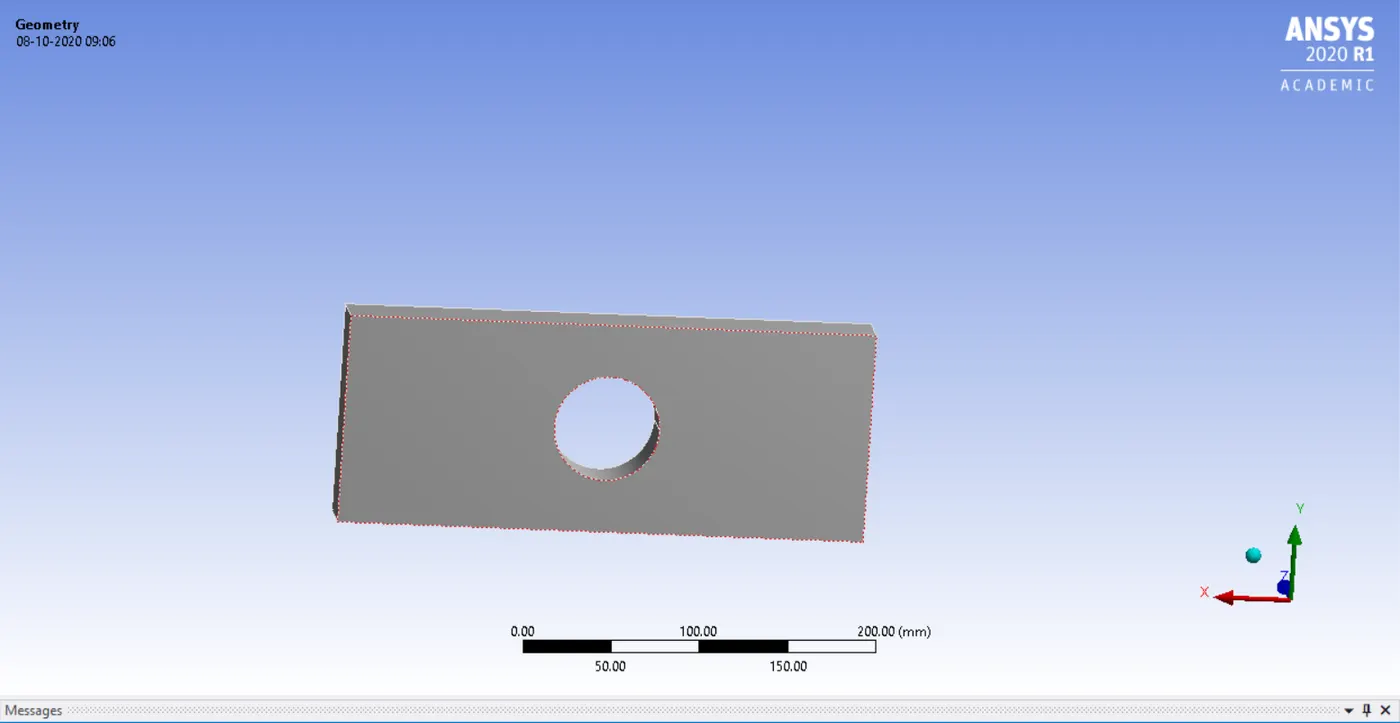
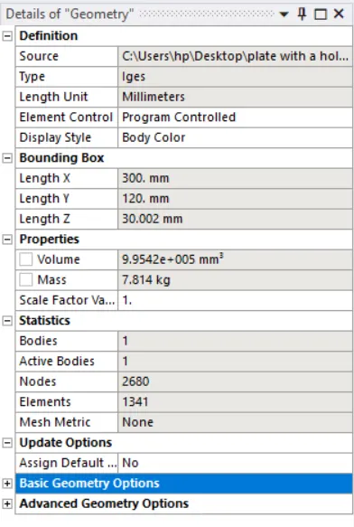
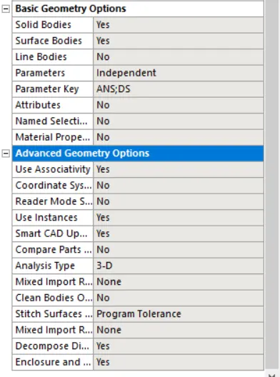
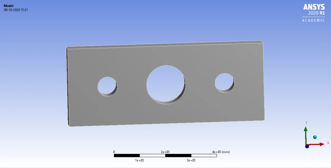
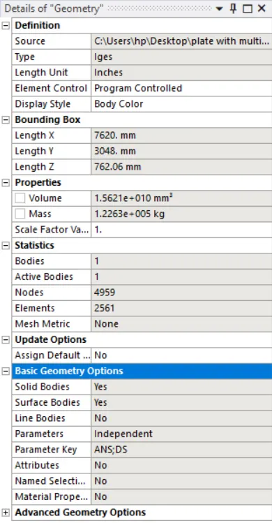
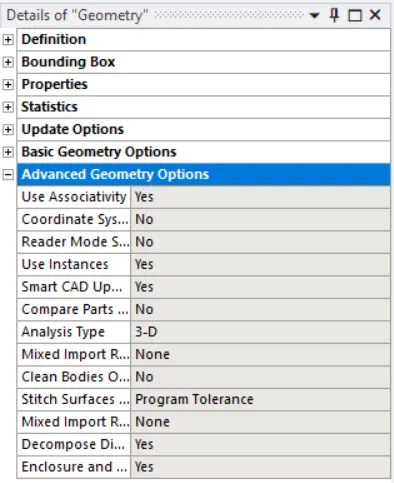
After the selection of the material from the engineering data sources, the required geometry was made in Space Claim. The final geometry along with its details used for the challenge is shown below.
Case 1
Case 2
Mesh
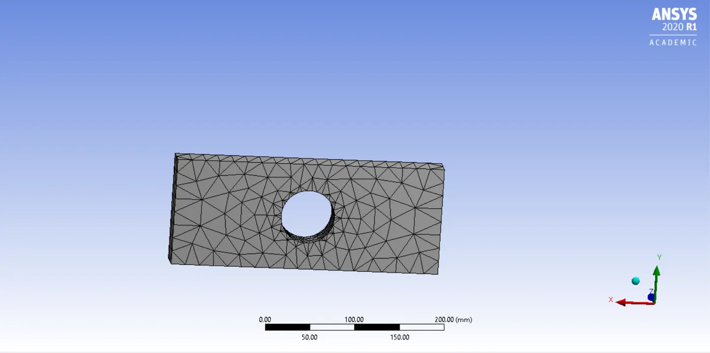
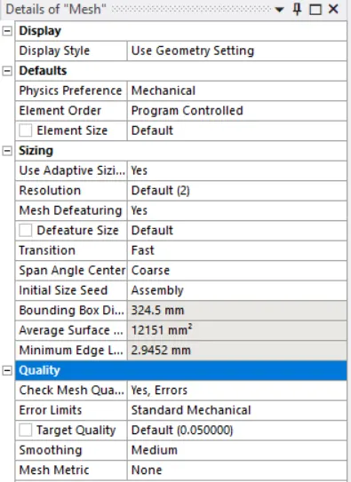
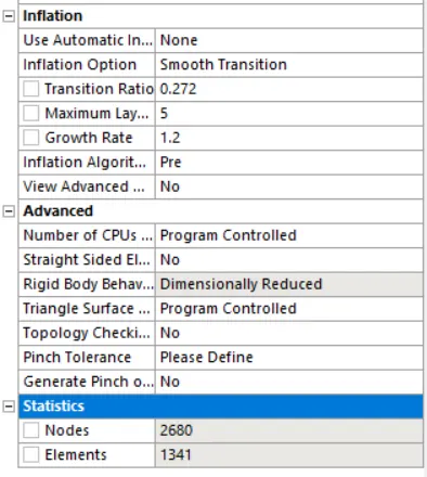
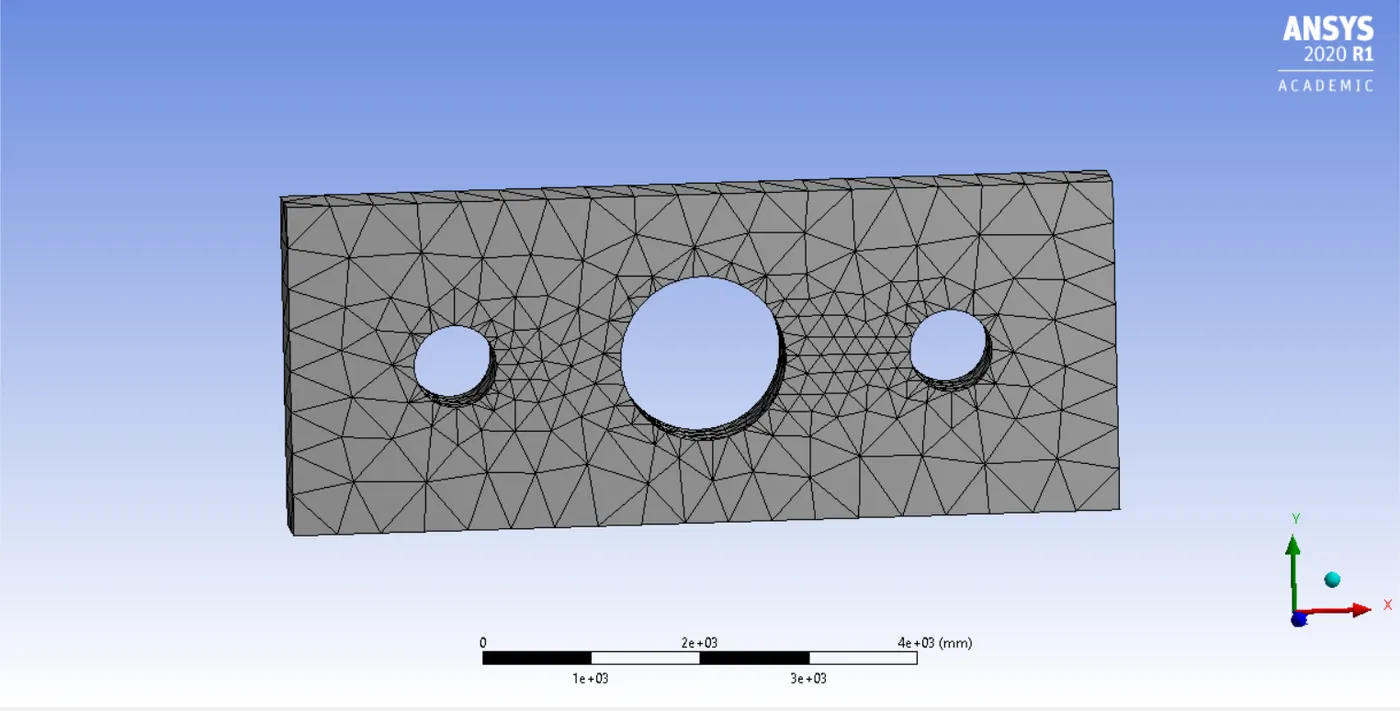
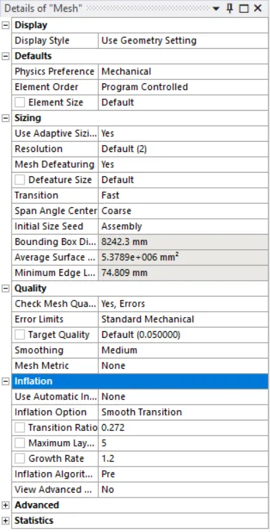
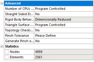
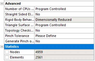
Once the geometry is updated, the mechanical GUI is opened for editing the model and conducting the required analysis. After checking the geometry and the material that is being used for the geometry, the mesh was specified. The mesh used in both the cases is default tetrahedron mesh.
The details of this are as mentioned below -
Case 1
Case 2
Fixed Support
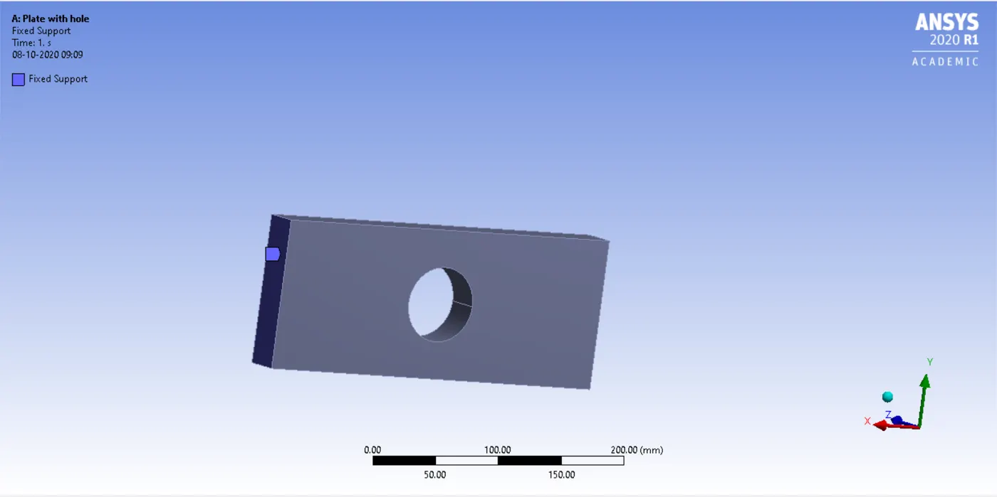
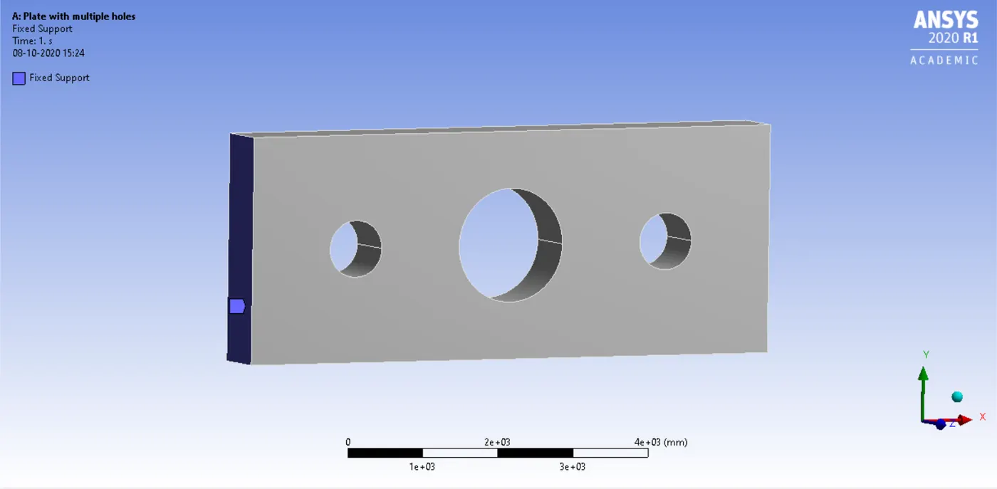
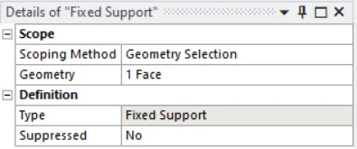
The meshing of the geometry is followed by the specification of fixed support and force. The fixed support for Case 1 and Case 2 is applied on the left side of the geometry as shown in the figures below -
Case 1
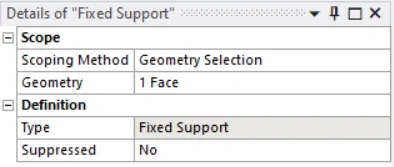
Case 2
Force Applied
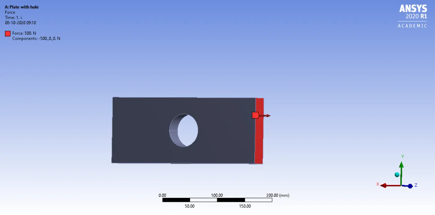
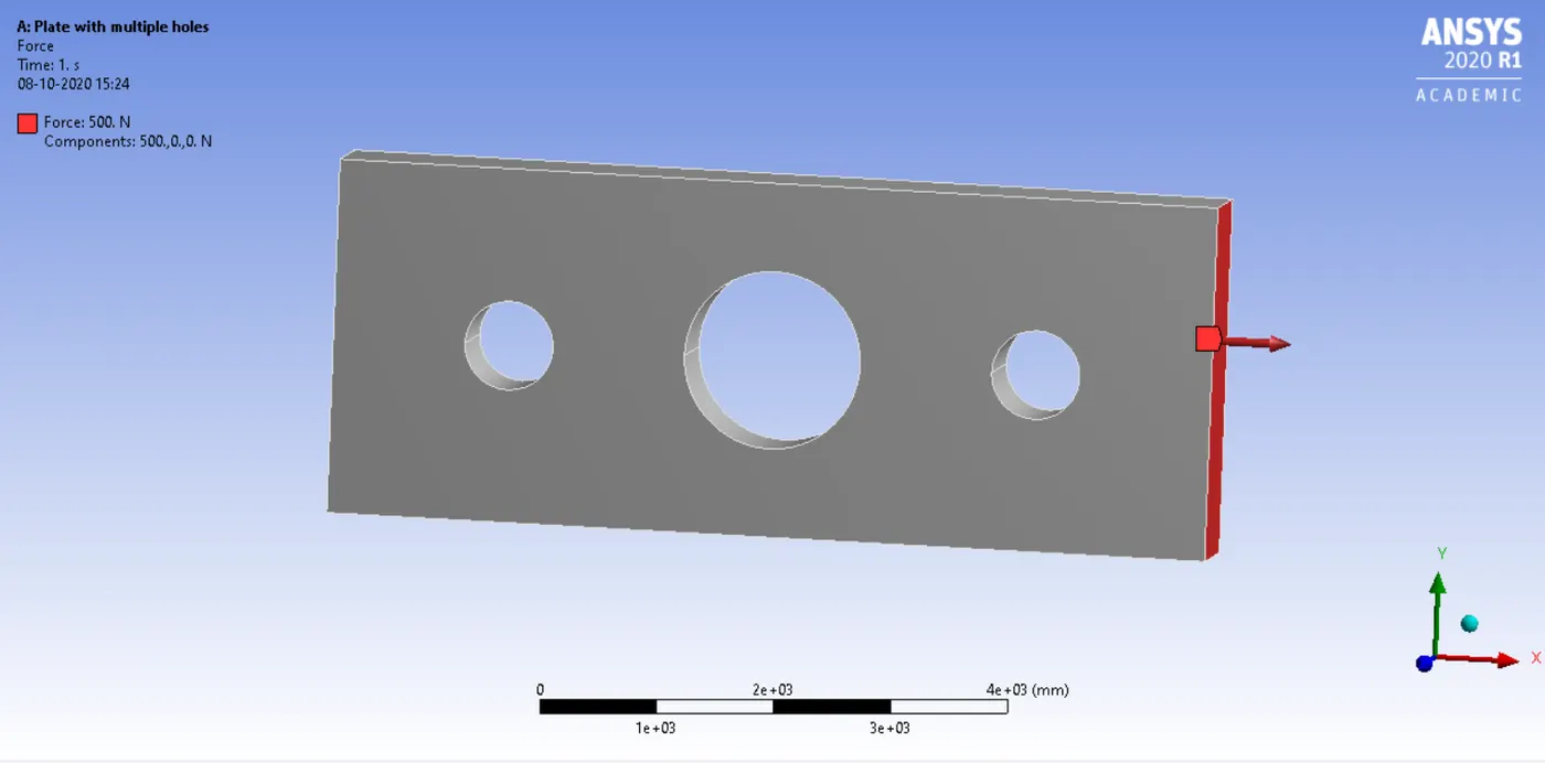
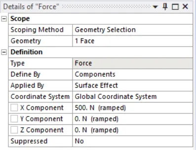
The force on both Case 1 as well as Case 2, is of 500N and in the opposite or positive x-axis direction. The application of force along with its details is mentioned in the figures below -
Case 1
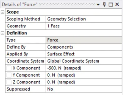
Case 2
Total Deformation and Maximum Principal Stress.
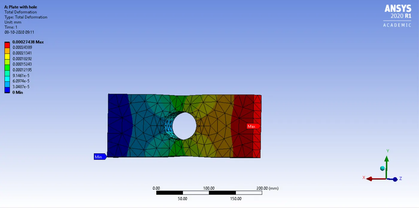
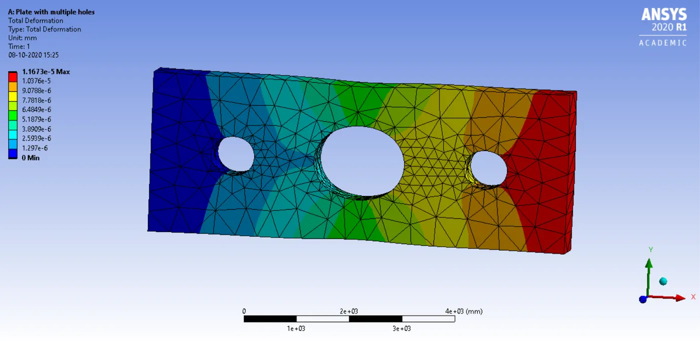
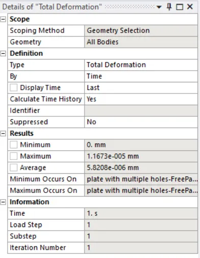
After the boundary conditions are set, the solver is run to find out the total deformation and the maximum principal stress for both the geometry. The total deformation for both the cases along with the details are shown below -
Case 1
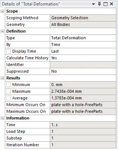
Case 2
Comparison of the total deformation
The values of the total deformation encountered in both cases have been mentioned in the table given below.
| Boundaries | Case 1 - total deformation | Case 2 - total deformation |
| Maximum value | 2.7348e-004 mm | 1.1673e-005 mm |
| Minimum value | 0 | 0 |
From the aforementioned table, the total deformation is less the case of Case 2 as compared to Case 1. The presence of more holes will lead to a higher value of deformation.
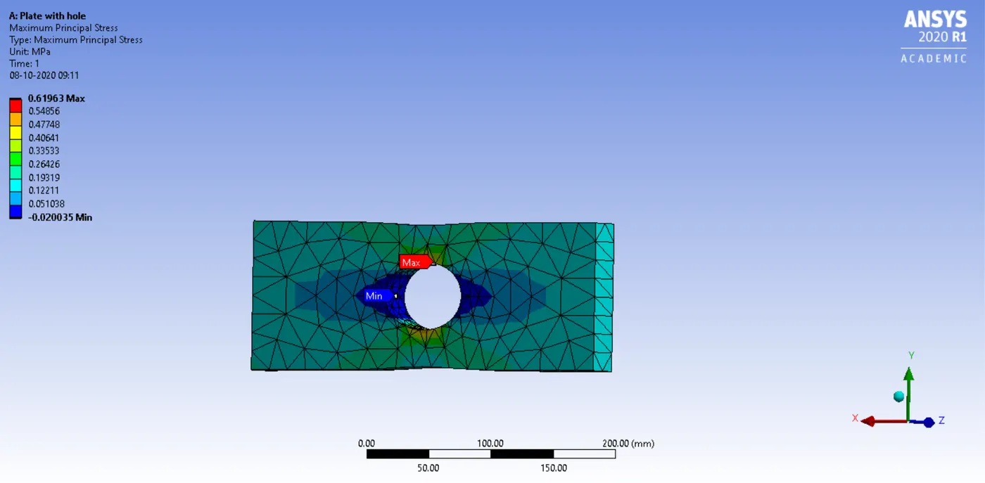
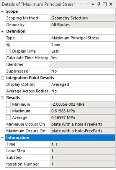
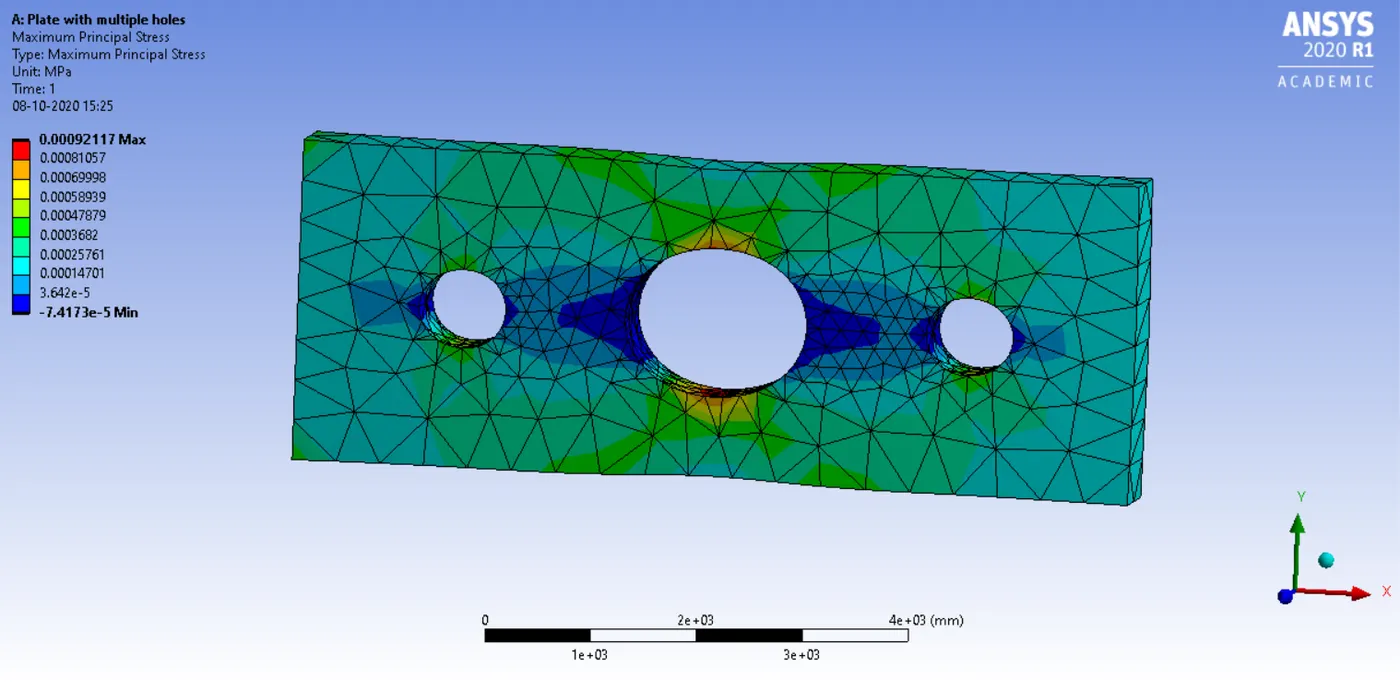
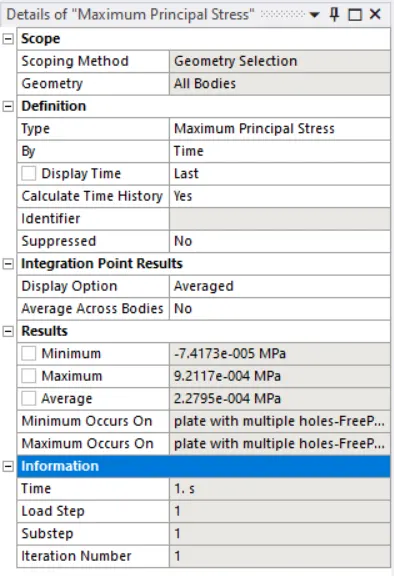
The maximum principal stresses for Case 1 and Case 2 are mentioned below -
Case 1
Case 2
Comparison of Maximum Principal Stress.
The table given below shows the maximum and the minimum value of the maximum stress that was developed in both the geometries.
| Boundaries | Case 1 - Maximum stress | Case 2 - Maximum Stress |
| Maximum Value | 0.61963MPa | 9.2117e-004MPa |
| Minimum Value | -2.0035e-002MPa | -7.413e-005MPa |
The value of the maximum stress encountered in Case 2 is less compared to the stress encountered in Case 1.
From the analysis standpoint, the design in Case 2 would be preferred. This is because the amount of total deformation taking place in Case 2 along with the maximum stress encountered, is less. Using a design that has lower chances of getting deformed and more resistant to the stress when force is applied to it than using a design that gets deformed easily and has less resistance to stress.
From the manufacturing standpoint, the design in Case 1 would be easier to manufacture as it has a single hole and would take less time to manufacture as compared to Case 2. Hence, it would be preferred. But if the component were to have less weight, then Case 2 would be preferred because portions of the materials have been removed which would result in a reduction of the weight.