Week 1 Stress Concentration on a Plate with hole
1. Case Study overview
1.1 Objective
Designing a plate with a single hole (Case 1) and three holes (Case 2) , simulating the two scenarios, and comparing the results of its maximum deformation and Von-Mises stress are the goals of this assignment. Additionally, it is necessary to identify which of the two circumstances will favor the analysis and which scenario will favor the manufacturing standpoint.
1.2 Dimensions
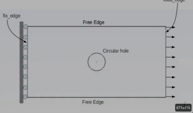
Plate dimensions Case 1:
Length=300mm
Height=120mm
Thickness=30mm
Circular Hole at the center:
Diameter=60mm
 <!--[endif]-->
Figure <!-- [if supportFields]> SEQ Figure \* ARABIC <![endif]-->1<!-- [if supportFields]><![endif]-->
Plate dimensions Case 2:
Length=300mm
Height=120mm
Thickness=30mm
Circular Hole at the center:
Diameter=60mm
Smaller holes 90mm away from center:
Diameter=30mm
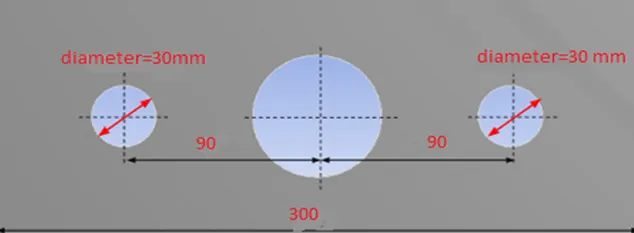
Figure <!-- [if supportFields]> SEQ Figure \* ARABIC <![endif]-->2<!-- [if supportFields]><![endif]-->
1.3 Boundary conditions:
Part type = Plate with holes
Material = Structural Steel
Tensile load = 500 N (pulling on one of the shorter side of the plate).
1.4 3D Modelling
3D Model prepared using Space Claim in ANSYS Workbench itself.
Case 1:
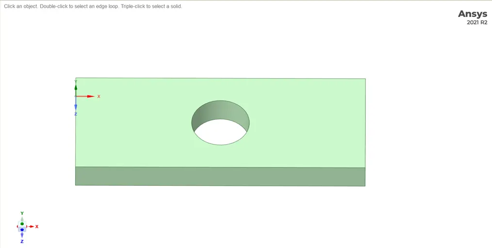
Figure <!-- [if supportFields]> SEQ Figure \* ARABIC <![endif]-->3<!-- [if supportFields]><![endif]-->
Case 2:
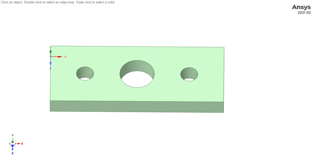
Figure <!-- [if supportFields]> SEQ Figure \* ARABIC <![endif]-->4<!-- [if supportFields]><![endif]-->
1.5 Material Properties
The basic material properties for structural steel mentioned in ANSYS Workbench are:
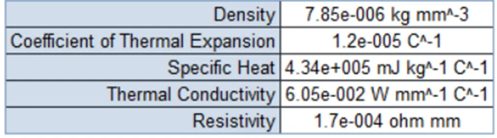
Figure <!-- [if supportFields]> SEQ Figure \* ARABIC <![endif]-->5<!-- [if supportFields]><![endif]-->
1.6 Meshing
A mesh size of 10 mm is chosen and applied
Case 1:
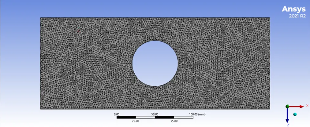
Figure <!-- [if supportFields]> SEQ Figure \* ARABIC <![endif]-->6<!-- [if supportFields]><![endif]-->
Case2:
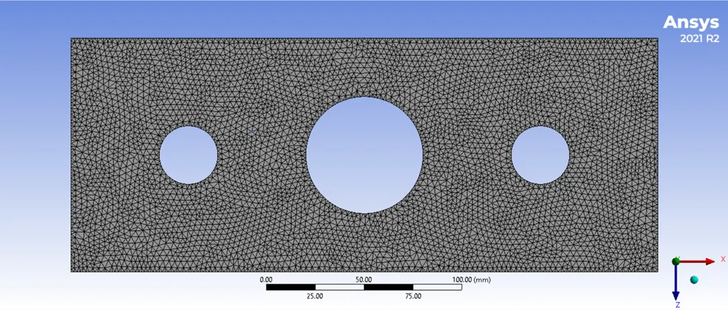
Figure <!-- [if supportFields]> SEQ Figure \* ARABIC <![endif]-->7<!-- [if supportFields]><![endif]-->
1.7 Results
The results of simulation after V-M stress and Max. deformation being chosen as the solutions are shown below.
Max Deformation:
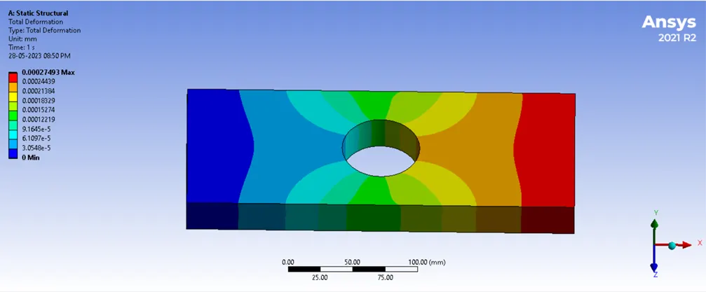
Figure <!-- [if supportFields]> SEQ Figure \* ARABIC <![endif]-->8<!-- [if supportFields]><![endif]--> Simulation result for Case 1
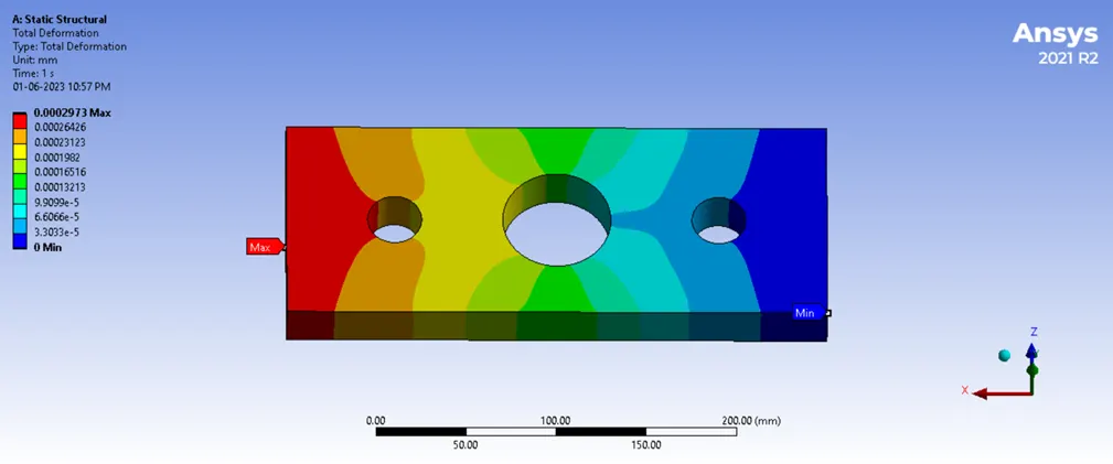
Figure <!-- [if supportFields]> SEQ Figure \* ARABIC <![endif]-->9<!-- [if supportFields]><![endif]--> Simulation result for Case 2
For case-1, it is observed that the maximum deformation of 2.7493E-4 mm has occurred near the face where the load is applied in the model.
For case-2 also, it is observed that the maximum deformation of 2.9730E-4 mm has occurred near the face where the load is applied in the model.
Von-Mises Stress:
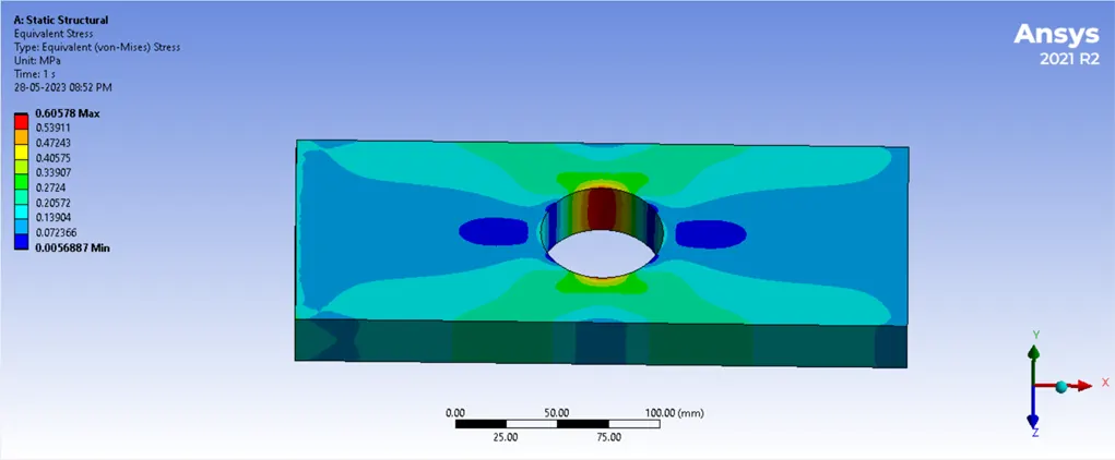
Figure <!-- [if supportFields]> SEQ Figure \* ARABIC <![endif]-->10<!-- [if supportFields]><![endif]--> Simulation result for Case 1
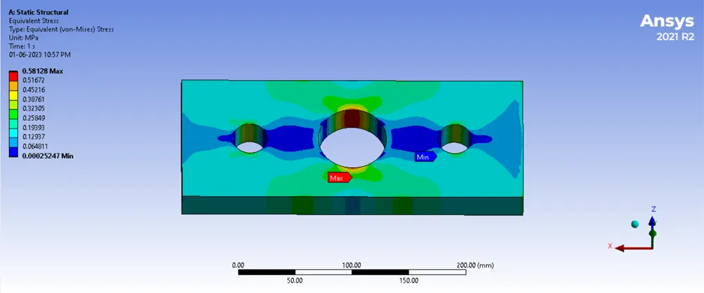
Figure <!-- [if supportFields]> SEQ Figure \* ARABIC <![endif]-->11<!-- [if supportFields]><![endif]--> Simulation result for Case 2
For case-1, it is observed that region having minimum cross-sectional area and material around the hole experiences the maximum stress of 0.60578 MPa. The region having maximum cross-sectional area and material around the hole experiences the minimum stress of 0.0056887 MPa.
For case-2, it is observed that larger hole region having minimum cross-sectional area and material experiences the maximum stress of 0.58128 MPa. The smaller hole region having maximum cross-sectional area and material experiences the minimum stress of 0.00025247 MPa.
2. Problem Statements
2.1 Compare the deformation and maximum stress developed on a structural steel model for the 2 cases
|
|
Total Deformation (mm) |
Von-Mises stress (MPa) |
||
|
|
Max |
Min |
Max |
Min |
|
Case-1 |
2.7493E-4 |
- |
0.60578 |
0.0056887 |
|
Case-2 |
2.9730E-4 |
- |
0.58128 |
0.00025247 |
The maximum deformation has occurred in case-2 i.e., plate with three holes because there is lesser material due to 3-hole condition.
The maximum value of Von-Mises stress is developed in the case-1 i.e., plate with single hole because of abrupt changes in geometry causing sudden deviation of stress flow lines around the hole.
2.2 From an analysis standpoint, which of the design will you select? Explain why?
We can clearly see that Case-2 i.e., plate with 3 holes, has lesser stress values. Hence after analysing that I would definitely select Case-2, although Case-2 being a slightly complex geometry it would consume slightly more computational time than Case-1 (1 sec more) but in the grand scheme of major phenomena like stress concentration, negligibly more computational time won’t have a greater impact.
2.3 From a manufacturing standpoint, which of the design will you select? Explain why?
From a manufacturing standpoint, these factors play a major role in manufacturing any part: ease in manufacturing, material cost, weight, machinability, production time. So keeping in mind all the above factors I would choose Case-1 as it optimizes all these factors when compared to Case-2.
For e.g. I would explain a few factors, it would be really easy to manufacture a plate with one hole than to manufacture a plate with 3 holes, it would also lessen the production time in manufacturing plate with 1 hole.