Week 1 Stress Concentration on a Plate with hole
STRESS CONCENTRATION ON A PLATE WITH HOLE
Case 1:
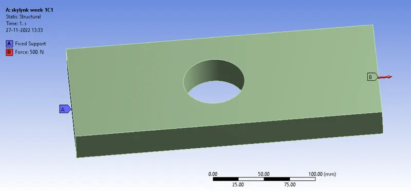
In this case the deformation and stress in a plate (L=300mm, B=120mm, T=30mm) with a hole of 60mm diameter at the geomentric center of the plate is analysed in ANSYS Workbench software by fixing a face and applying 500N tensile force on the opposite side. Refer the image below dor 3D modeland the Boundary conditions applied for it. Model is designed in Spaceclaim
Properties of the material specifies for the model are
Material : Structual steel
Density : 7850 Kgm^-3
Tensile yield Strength : 2.5E+08 Pa
Compressive Yield Strength : 2.5E+08 Pa
Tensile Ultimate Strength : 4.6E+08 Pa
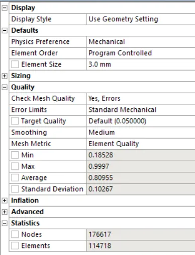
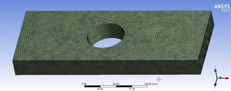
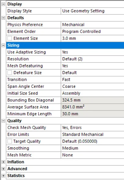
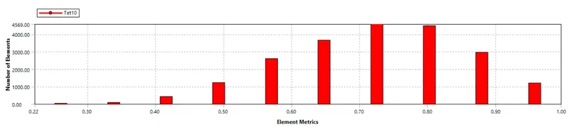
The meshing is done in ANSYS with an element size of 3mm and a Patch confermation method using Tetrohedrons was employed. meshh quality and the mesh metric graph is given below:

refer the image below for Model after meshing:
Case 2:
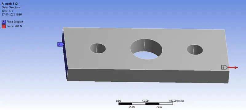
In second case more two holes of 30mm diameter are introduced on the eighter side of the center hole with 90mm distance from center and same one side is fixed and other side with 500N tensile force. Deflection and Stress is observed using ANSYS workbench software. The image below is the 3D model of designed model with boundry conditions.
Material Properties are same as case 1
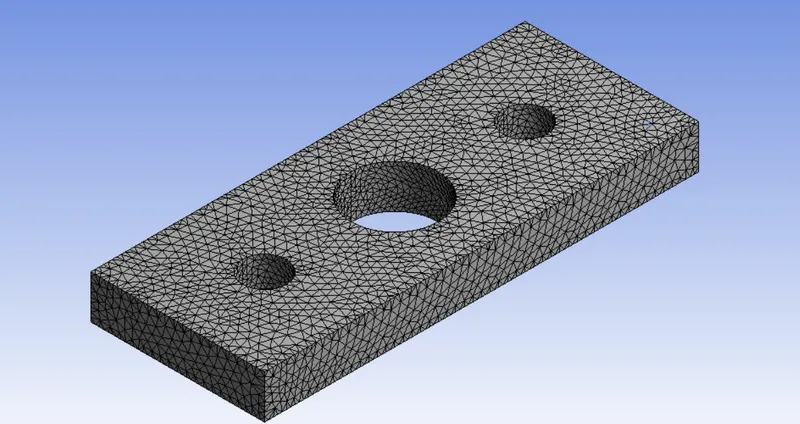
The meshing is done in ANSYS with an element size of 3mm and a Patch confermation method using Tetrohedrons was employed. meshh quality and the mesh metric graph is given below:
The mesded model look like beolw:
RESULTS
For the above cases the Total Deformations and Equivalent stresses are analysed.
comparing the both results
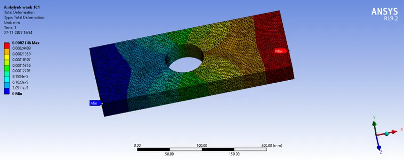
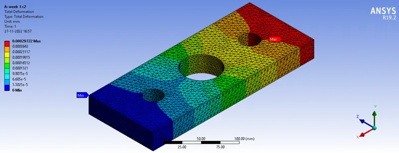
Total deformation:
Time[s] Minimum[mm] maximum[mm] Average[mm]
1) 1 0 2.746e^004 1.3982e^-004
2) 1 0 2.9722e^-004 1.4556e^-004
Images below are total deformation plots of case1 and case2:
case 1:
case2 :
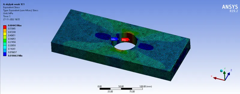
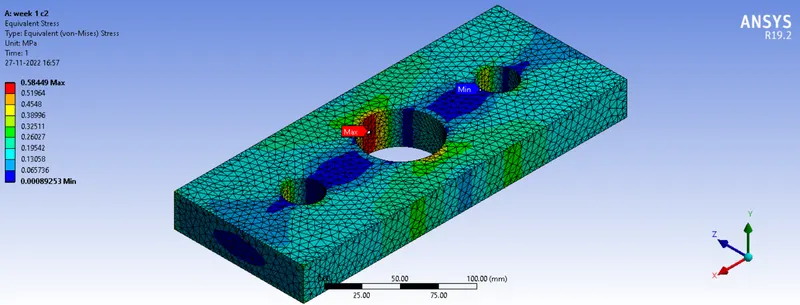
Equivalent Stress:
Time[s] Minimum[MPa] maximum[MPa] Average[MPa]
1) 1 1.0663e^-002 0.60443 0.16141
2) 1 8.9253e^-004 0.58449 0.1695
images below are the Images of Equivalent Stress of each case
Case1:
Case2:
Conclusions:
-> The Total Deformation in the case 2 is more compared to case1. In case2 more material is removed for two more hole which decreses the tensile strength of the model.
-> The Maximum Equivalent Stress is more in case1 compared to case2. in case2 due to the addition of holes the stress is distributed thoughout the model, as their is only 1 hole in the case 1 stress concentration is more hence more Max Equivalent stress in case1
-> From the Analysis Standpoint, i will select case2 because the distribution of stress concentration points are more and has less Max equavelent stress for same amount of tensile force
-> From Manufacturer Standpoint case1 has been selected because less material is drilled and less manufacturing process is required.