Week 1 Stress Concentration on a Plate with hole
- Objectives: -
To compare the deformation and maximum stresses generated in the two give cases and draw conclusions from the results. - Model Details: -
Geometry:
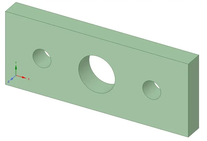
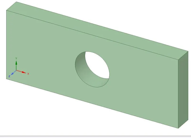
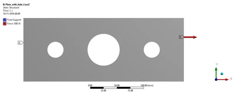
Both the cases have the same plate of 300 mm×120 mm dimensions and 30 mm thickness. In Case-1 there is a central hole of 60 mm diameter, while in Case-2, two more of 30 mm diameter are also placed horizontally, at a distance of 90 mm from centre of central hole on either sides.
Mesh:
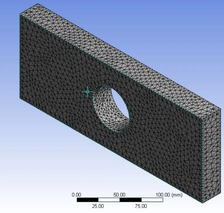
Case-1
Analysis type: - Static (Steady-state)
Element Method: - Tetrahedron
No. of nodes: - 26230
No. of elements: - 14674 (Element size – 3.5 mm)
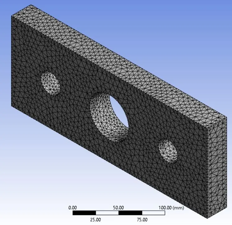
Case-2
Analysis type: - Static (Steady-state)
Element Method: - Tetrahedron
No. of nodes: - 29044
No. of elements: - 16264 (Element size – 3.5 mm)
Material:
For comparison, material is kept same for both cases,
Structural Steel
Young’s Modulus = 200 GPa
Poisson’s Ratio = 0.3
Density = 7850 Kg/m3
- Loads & Constraints: -
Again for comparison purpose, load applied is kept same for both cases. In both cases, along the length, the left face is fixed support and right face is applied with 500N force in tensile manner.
- Results: -
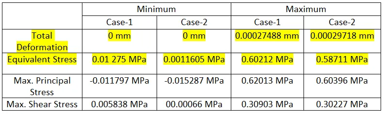
For comparing the effects of holes, we will compare the Total Deformation and Equivalent Stresses in the two cases, which are tabulated as below,
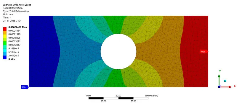
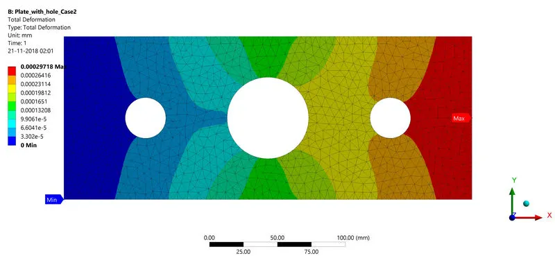
Total Deformation:-
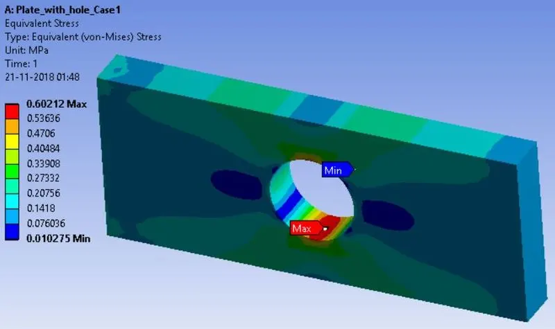
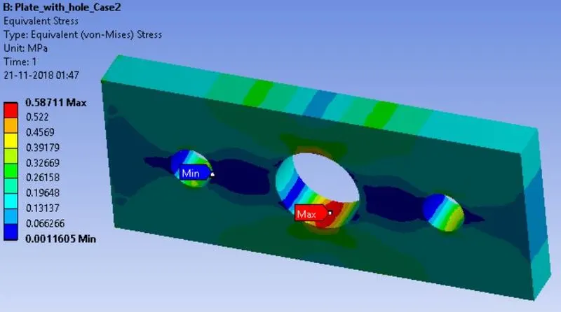
Equivalent Stress:-
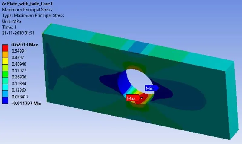
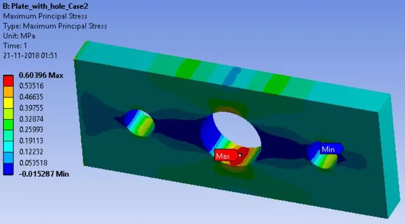
Max. Principal Stress:-
Max. Shear Stress:-
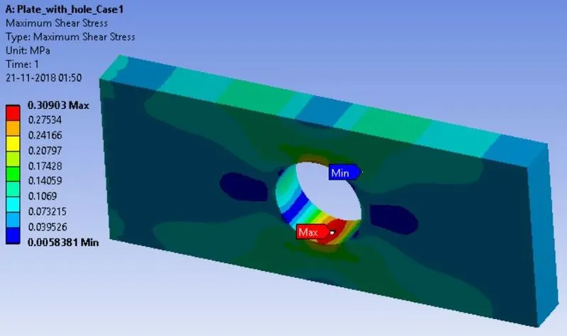
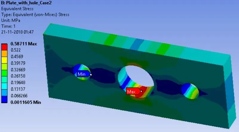
- Conclusion:
It is clear from the results above that, due to introduction of two holes, adjacent to the central hole, there is a reduction in the maximum values of Equivalent Stress, Max. Principal Stress and Max. Shear Stress. So for any material following any Theory of Failure, Case-2 will be safer considering stresses.
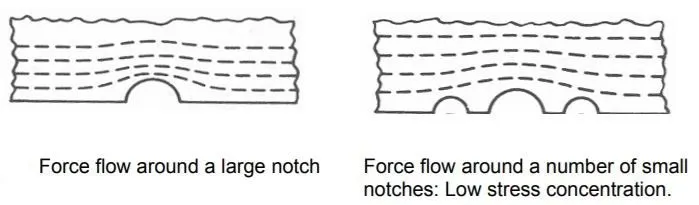
The Total Deformation and Equivalent Stresses of Case-1 and Case-2 are tabulated above. So, for the same material and under same loading, Case-2 will be deformed more compared to Case-1, due to two extra holes. However these holes helps in reducing the maximum stress value due to smoothening of the force flow lines, as illustrated in the Fig. below,
From an analysis stand, I will select Case-2, considering the reduced maximum stress values. In Case-2 increase in Total Deformation is less than a micron, but it shows a decrease of around 0.015 MPa, which will improve the Factor of Safety of the component. Especially in Brittle materials, where discontinuities can cause the initiation of cracks, Case-2 will help in minimising this effect.
But from manufacturing stand, I will select Case-2, considering the machining of extra two holes, which will add to the cost of manufacturing. Manufacturing cost is decided by amount of machining time, number of drills etc.
So in conclusion, if the component is not critical in design, i.e. high FoS has been taken, then 2.5% reduction in stress is not considerable, and from cost analysis, Case-1 should be selected. However if the component is critical part of design, Case-2 should be selected.