Week 1 Spur Gear Challenge
ANALYSIS OF A SPUR GEAR
OBJECTIVE
To perform contact simulation of two spur gears to determine the Equivalent stress, Total deformation, and Stress intensity and to determine if any possible fracture could occur during its operation.
Three cases of the same simulation is carried out with different materials to determine the most suitable material for the application.
PROCEDURE:
Since all three cases will be performed on the same geometry but with different materials, all three required material models can be imported onto the engineering data at the beginning of the simulation. These models can then be duplicated onto another static simulation file.
The required material model data is shown below. If any material is not found on the engineering database then it can be created by specifying its mechanical properties.
The cast iron material data is available in the Granta Design sample materials library (in-built)
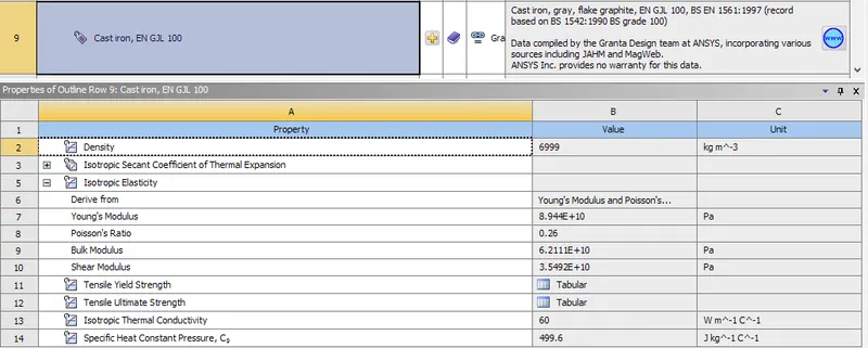
However there is no material data for both cast steel and cast bronze. So we create a new material on a new user-defined library to save the two new materials. These materials can be create using their respective mechanical properties shown below
After the 2 materials are created, all three can be added to the current database.
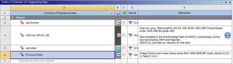
CASE 1: Cast iron
- The solid part (.sldprt) is imported onto the geometry module
Material
- The cast iron material is added to the two geometry components.
Contact
- The contact regions are specified on both geometries.
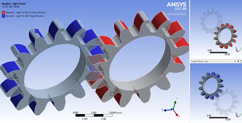
- Then the properties of the contact like friction, formulation method (lagrange) etc are specified.
Revolute joint
- A revolute joint is created on the centre point of both the components using the contact option.
Analysis settings
- Then the type of analysis and other simulation parameters like time step, no of steps etc are defined from the analysis settings.
Mesh
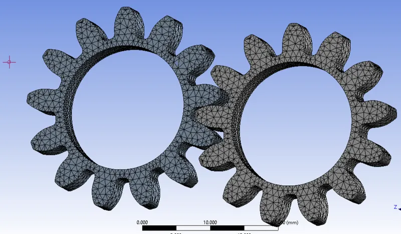
- 3D tetra solid mesh is generated on both the model and a mesh target length of 0.5mm is set to generate a more dense mesh
- The generated mesh is shown below
Joint load
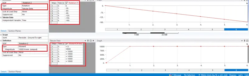
- A joint load is applied on both the revolute joints of both components
- A rotational motion is specified (in deg) on the left joint in the anti clockwise direction and a moment of 10N.mm at each time step
- NOTE: The rotation motion is applied in a tabular group since it varies with each time increment. However a constant moment of 10N will be applied at every time step hence it can be defines as a constant rather than a time dependent function.
Output parameters
- The following results are requested: Equivalent (von-mises) stress, total deformation and stress intensity.
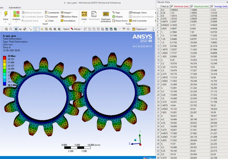
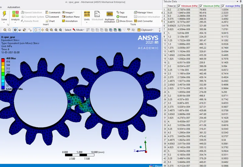
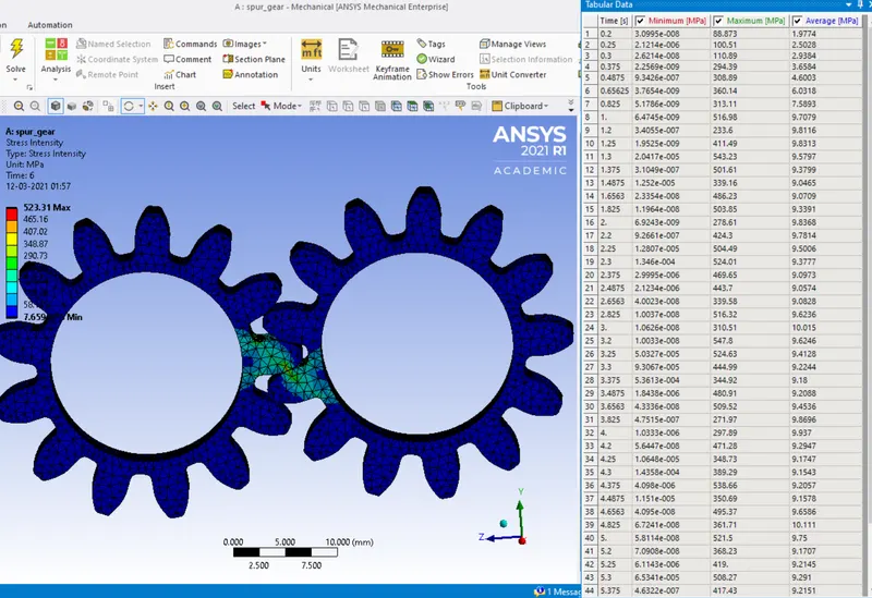
The maximum, minimum and average values extracted for all three variables for a time step from 0.2 - 6 (with increments in the range of 0.05 - 0.5) is show below
Total deformation

Equivalent stress

Stress intensity

CASE 2: Cast steel
The material data and geometry model can be duplicated and shared onto another static analysis project.
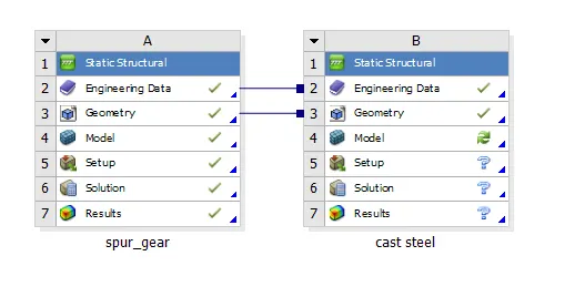
Similar to the previous analysis setup, all necessary modifications are made to the model in the following order
- Material (cast steel)
- Contact
- Revolute joint
- Analysis setting
- Mesh
- Joint load
- Output parameters
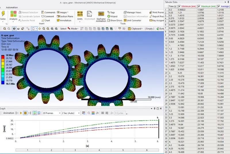
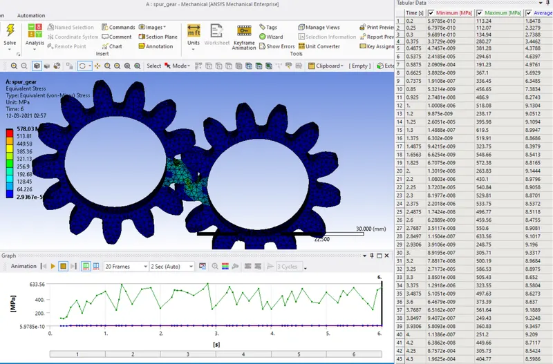
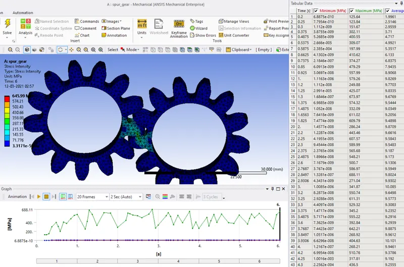
The maximum, minimum and average values extracted for all three variables for a time step from 0.2 - 6 (with increments in the range of 0.05 - 0.5) is show below
Total deformation
Equivalent stress (von-mises)
Stress intensity
CASE 3: Cast Bronze
Similar to the previous analysis setup, all necessary modifications are made to the model in the following order
- Material (cast bronze)
- Contact
- Revolute joint
- Analysis setting
- Mesh
- Joint load
- Output parameters
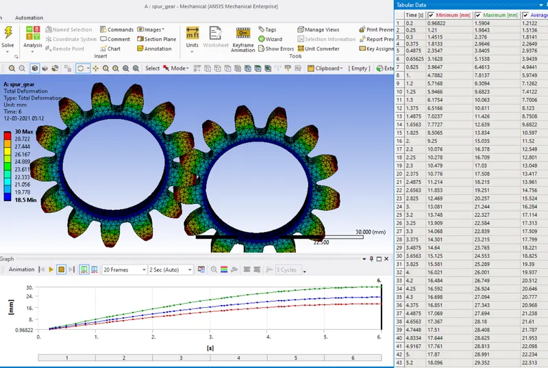
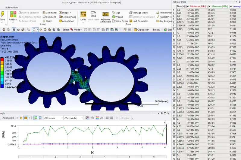
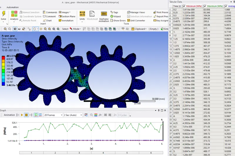
The maximum, minimum and average values extracted for all three variables for a time step from 0.2 - 6 (with increments in the range of 0.05 - 0.5) is show below
Total deformation
Equivalent stress
Stress intensity
CONCLUSION
Hence all the extracted data from all three cases are shown below
| Maximum (of) | Total deformation (mm) | Equivalent stress (MPa) | Stress Intensity (MPa) |
| Cast Iron | 30 (Max) | 468 (Max) | 523.3 (Max) |
| 18.5 (Min) | 6.6e-5 (Min) | 7.6e-5 (Min) | |
| Cast Steel | 30 (Max) | 578 (Max) | 645.9 (Max) |
| 18.5 (Min) | 2.9e-5 (Min) | 3.3e-5 (Min) | |
| Cast Bronze | 30(Max) | 437.2 (Max) | 483.72 (Max) |
| 18.5 (Min) | 3.0e-5 (Min) | 3.4e-5 (Min) |
From the above results, we can conclude that,
- The stress generated, both von-mises stress and the stress intensity, is higher in the case of Cast steel and comparatively less for Cast iron followed by Cast bronze.
- It can also be noted that the deformation is almost the same in all three cases. Hence it is the young's modulus of each material that affects the stress developed in the model.
Hence from the above three materials, modeling the spur gears with a cast bronze would yield a longer life cycle and the possibility of occurrence of fracture is higher in the case of cast steel since the internal stress generated on the teeth feature of the gear during contact is highest compared to the rest.