Spur Gear Challenge
AIM
To setup a static analysis deck in ansys for the spur gear to find out the equivalent stress, maximum deformation and stress intensity in the gear. And also find out the point of fracture in the gear as the gear tooth comes in contact.
CASE SETUP
Open the ansys workbench first and drag the static structural analysis into the program schematic and then in the engineering data add the materials CAst Iron ductile, Cast Stel. But the Cast Bronze is not available in the library so we need to add the material into the library. For that click on the area ask for click to add the material an edit its name to cast Bronze and on the physical properties a add the relevant properties like density , young’s modulus, poison ratio, Ultimate stress, Yield stress etc and edit all the values with the data provided in question.
Then in the geometry we need to add in the stp file of spur gear in contact.
After that the we need to enter the mechanical module of the ansys and we need to setup the deck. In the model first we need to assign the materials to the geometry.
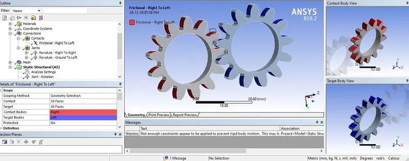
Next step is to check the connections. Right click on it and select rename based on definition. This will find out the contacts automatically .But this can recognize only the contacts at the start of the simulation. We need to define the contacts for the entire simulation. So in contacts we edit the source and target surfaces. In source case we need to select all the tooth faces of one gear and on the target we need to select the faces on the other gear tooth.
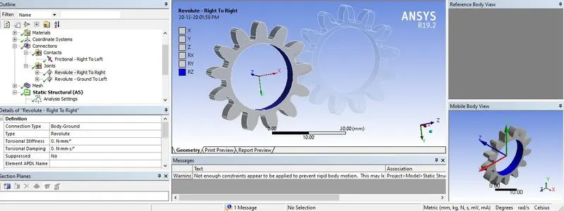
As we have gear joints which is having the rotation along an axis which is same as the revolute joint, we need to create the revolute joints to get the rotation about the axis. So create two joints and set the scope by selecting the inner faces of the gear .If the dof applied is not in the direction of the coordinate system axis , change the axis manually and make it aligned with the dof.
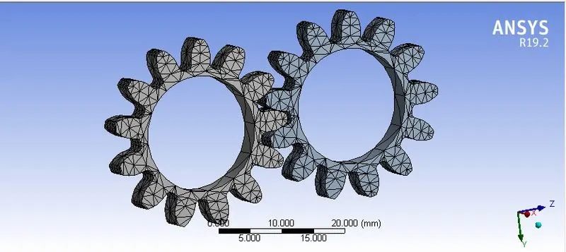
Mesh (1mm)
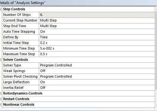
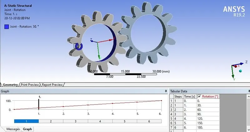
Then what we need to do is to create a joint load on those two joints. On the left gear, we can give the rotation along the free axis by giving rotation in angles in steps. Here we decided to have 6 steps and we divide the 180 degree rotation in 6 steps. Each rotation is about 30 degrees each
Joint-Rotation
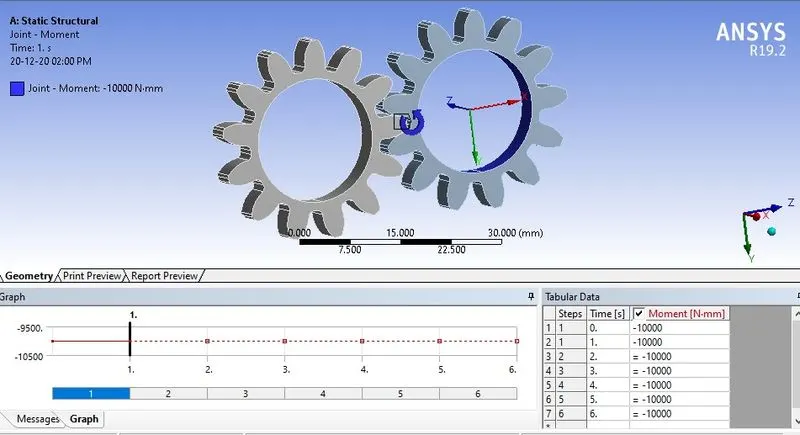
Joint-Moment
Results
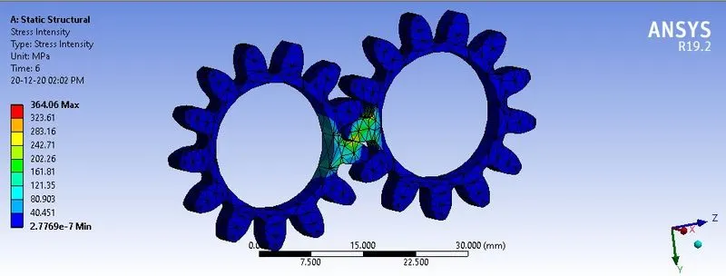
Case 1 Cast Iron
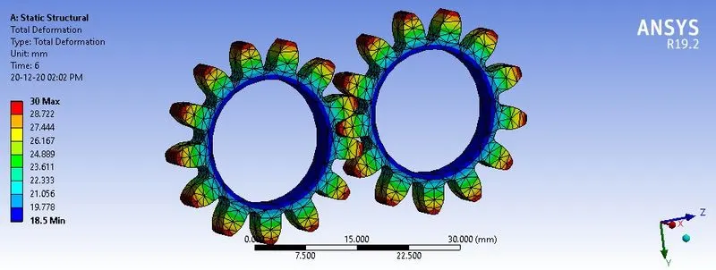
Total Deformation
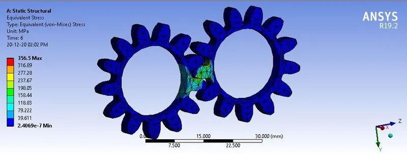
Equivalent stress
Stress Intensity
Case 2 (Cast Steel)
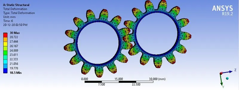
Total Deformation
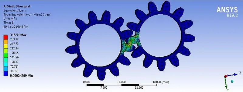
Equivalent stress
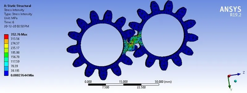
Stress intesity
Case 3 (Bronze, Cast)
Total Deformation
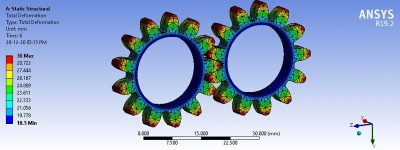
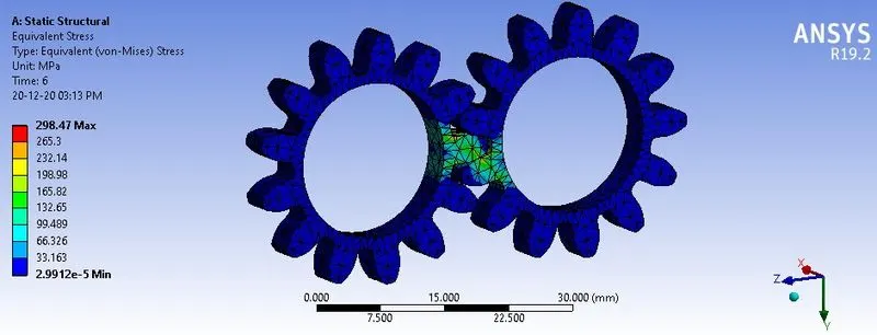
Equivalent stress
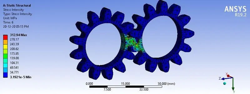
Stress Intesity
| EQUIVALENT STRESS ( Max) ( in MPa ) | MAXIMUM DEFORMATION (Max) ( in mm ) | STRESS INTENSITY ( MPa) | |
| Case 1 | 356.5 | 30 | 364.06 |
| Case 2 | 318.51 | 30 | 352.76 |
| Case 3 | 298.47 | 30 | 312.94 |
Conclusion
We can see that in all cases the deformation happens to the gear is maximum of 0.03 m .But the equivalent stress and stress intensity is slightly on higher side in case 1 which is of material Casrt Iron . Similarly the cast bronze is also a brittle material.Stresss intensity simiply means the stress value which is maximum at a point.So the stress intensity value is also on higher side in cast bronze . So more chances of the gear failue happens to the this case.So we can safely use the cast iron ductile for making the gear.