Week 1 Spur Gear Challenge
Spur Gear
The given module was downloaded as instructed. The geometry of the spur gear is given below. The two gear wheels were renamed as Left and Right.
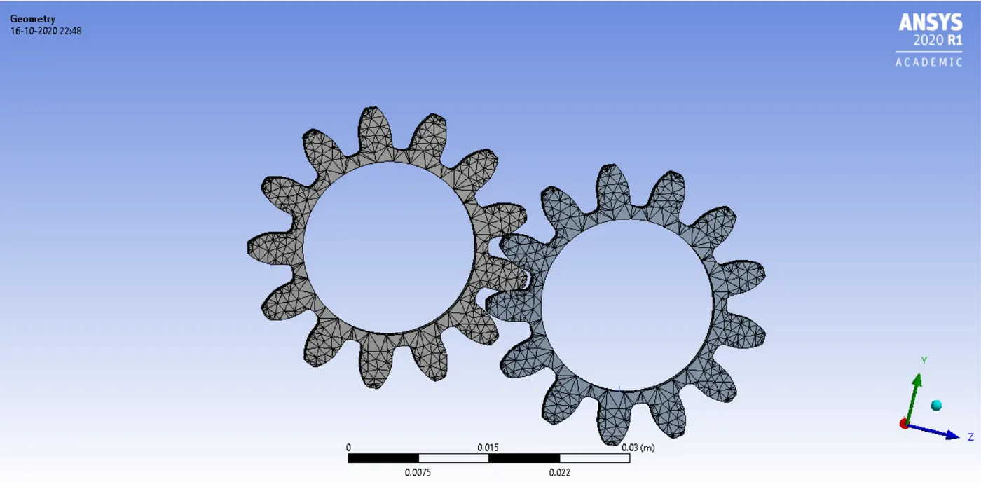
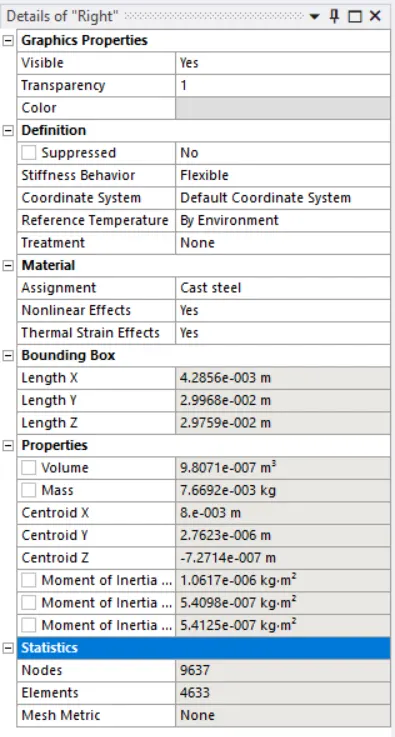
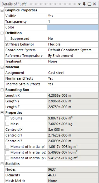
The details of the geometry are mentioned below.
Right
Left
OBJECTIVE 1
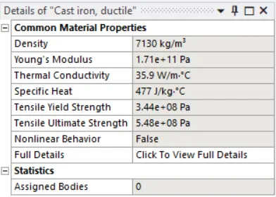
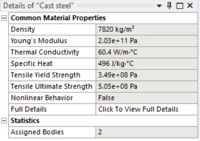
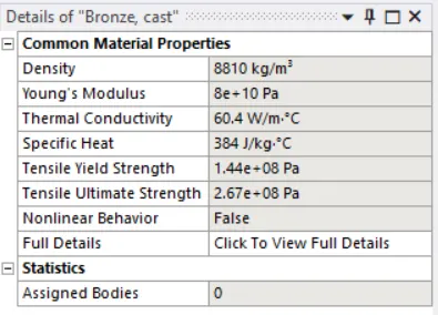
The materials required for this particular assignment was inserted from Granta Samples in the engineering data. The details of the materials used are given below.
Cast Iron (ductile)
Cast Steel
Cast Bronze
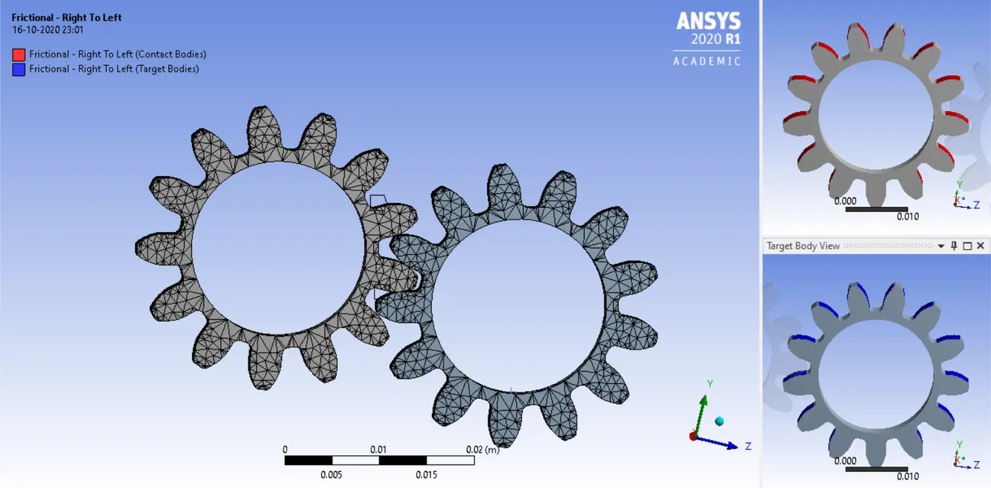
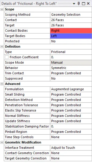
Following the specification of the materials, the connections in the module were specified. The faces were selected and specified as contact and target bodies.
The details of the connections have been mentioned below.
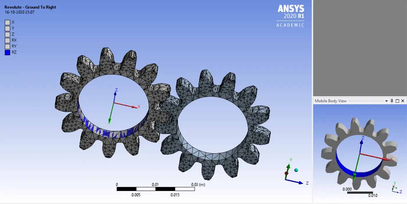
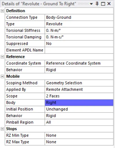
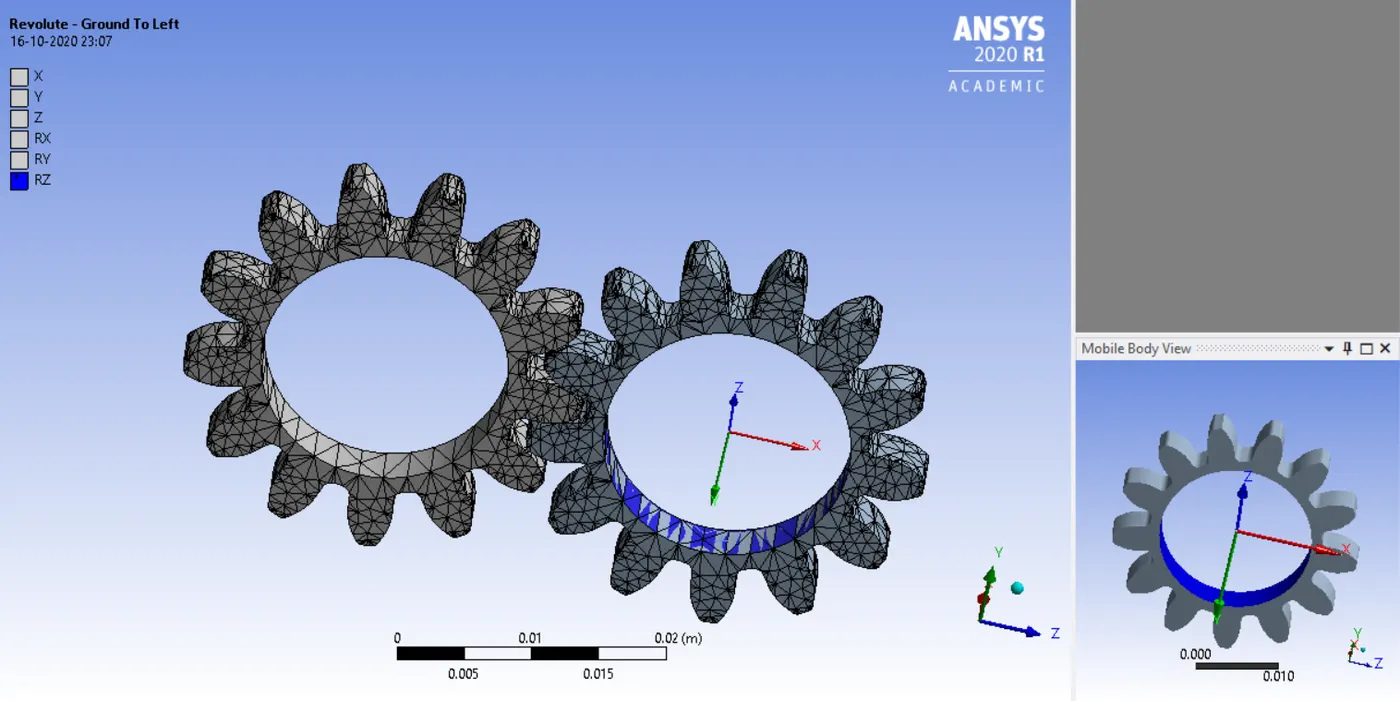
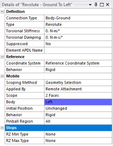
The joints of the gear were also specified.
Details of the joints.
Revolute Joint - Ground to Right
Revolute Joint - Ground to Left
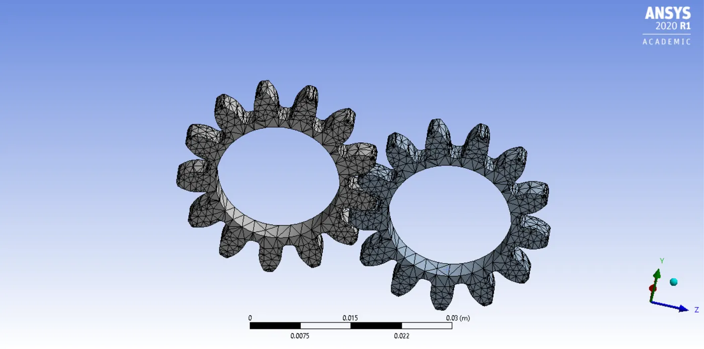
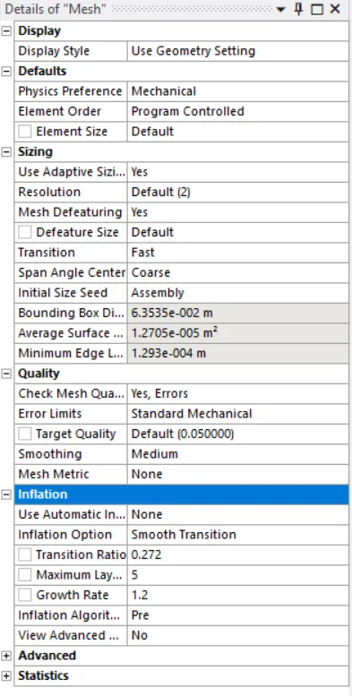
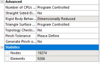
The mesh used in all cases of this assignment were a default mesh. The details of this mesh have been mentioned below.
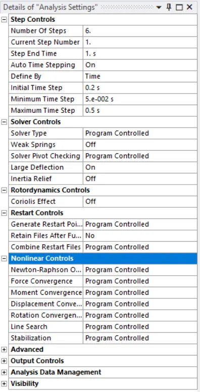
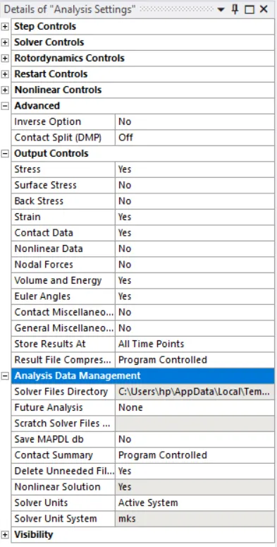
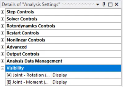
Once the mesh was applied, the analysis settings were changed before applying the joint loads.
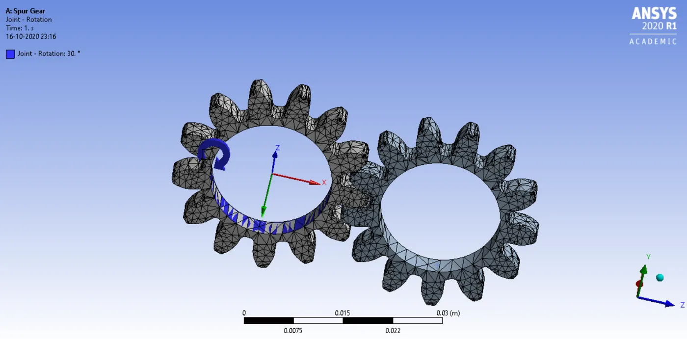
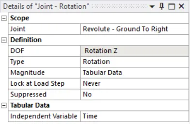
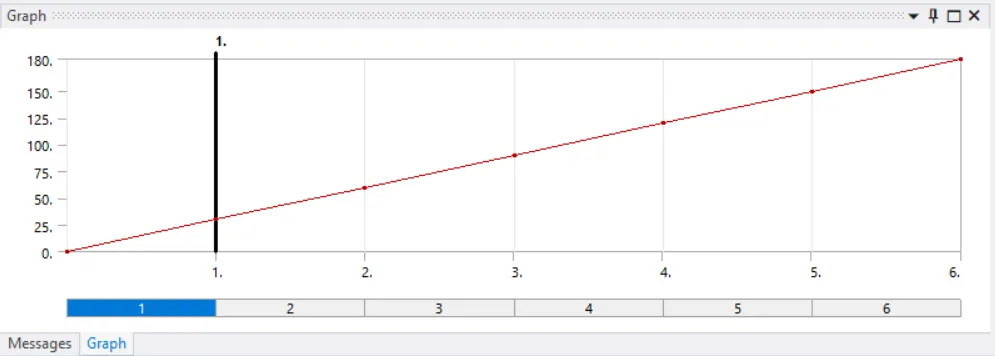
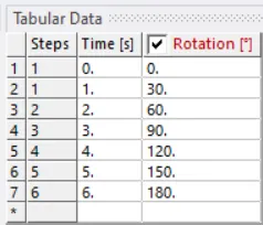
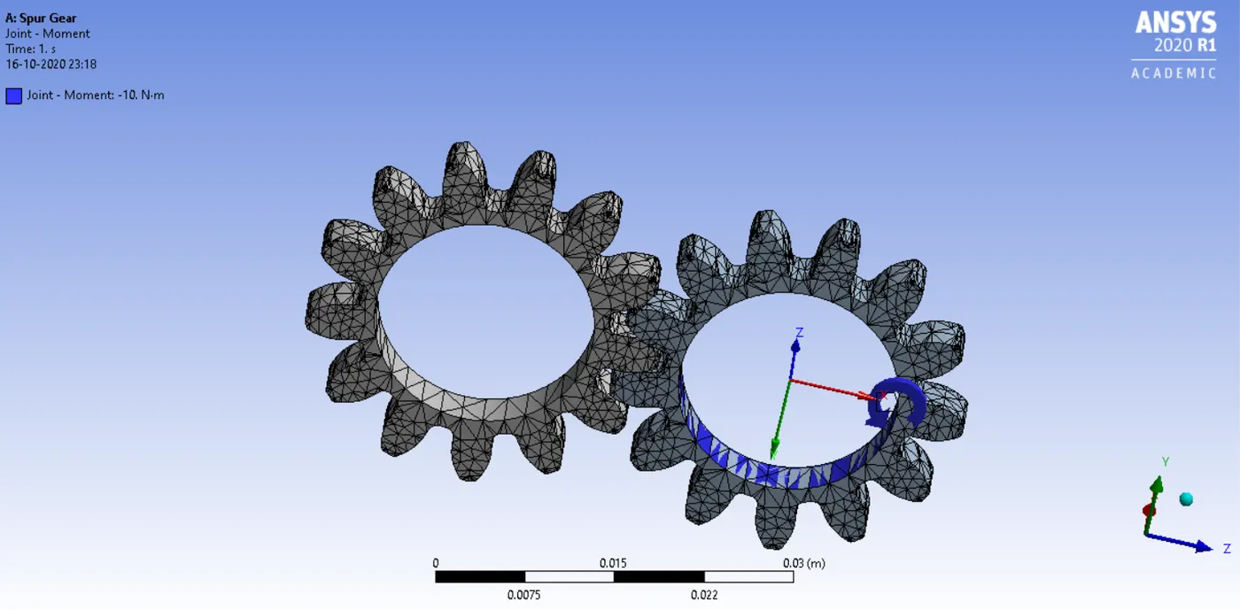
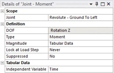
From the static structural, two joint loads were inserted. One was specified as the moment and the other was specified as rotation. The values for both had been specified using tabular data like the one mentioned below.
The details of the joint load.
|
Joint Load |
Type – Rotation |
|
Joint Specified |
Ground to Right |
|
Magnitude |
Tabular Data |
|
Joint Load |
Type – Moment |
|
Joint Specified |
Ground to Left |
|
Magnitude |
Tabular Data |
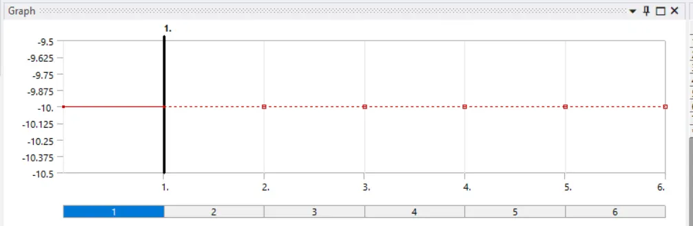
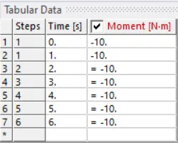
After specifying the joint loads, the simulation was run for the solutions of total deformation, equivalent (von-missus) stress, and stress intensity respectively.
Case 1
For case 1, the material used was Cast Iron (ductile).
For the solution, equivalent stress or von-missus stress, total deformation, stress intensity was inserted.
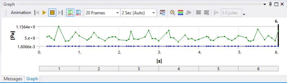
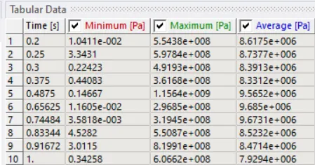
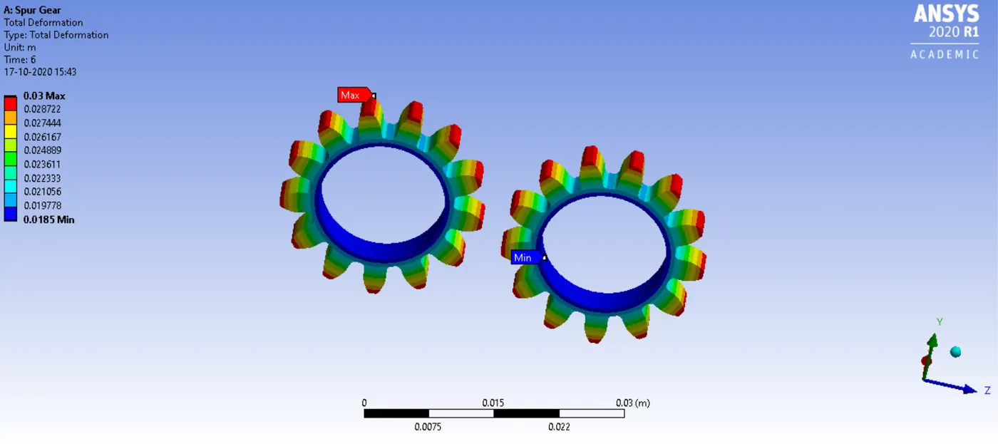
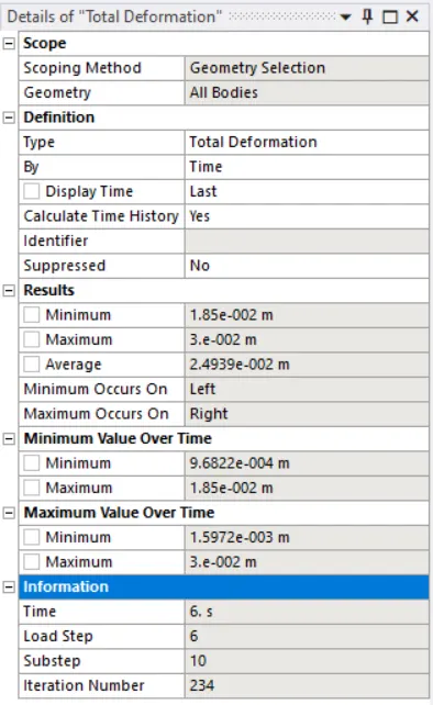
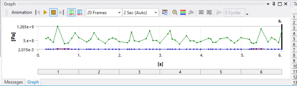
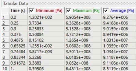
The maximum and minimum values for these boundary conditions have been mentioned below.
|
Boundary Conditions |
Maximum Value |
Minimum Value |
|
Von-missus stress |
5.7259 Pa |
2.015e-003 Pa |
|
Total Deformation |
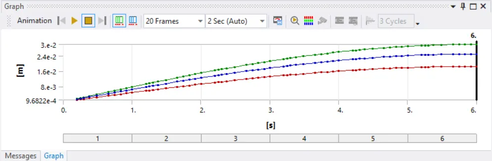
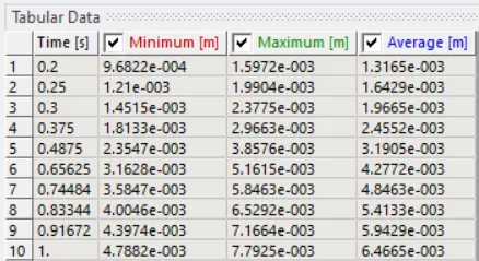
3e-002 m |
1.5972e-003 m |
|
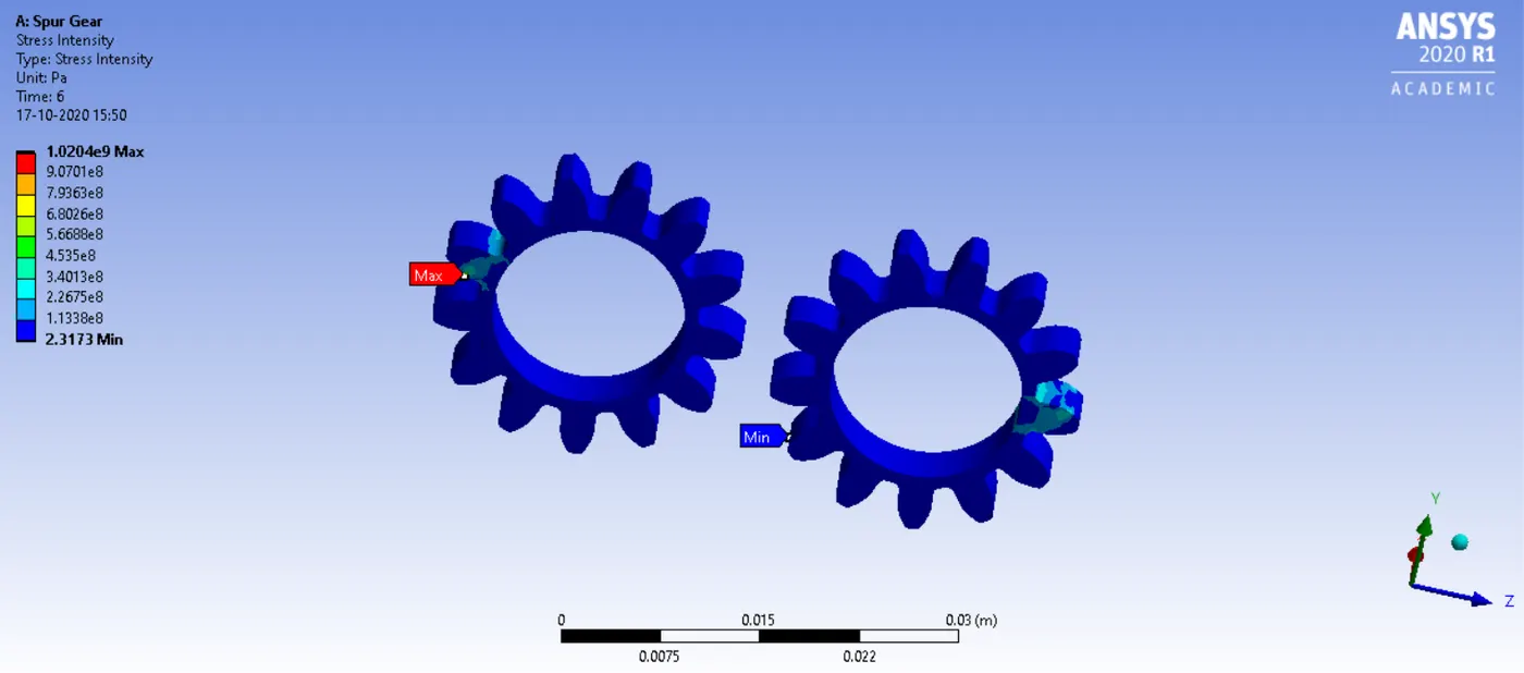
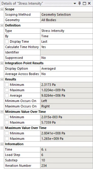
Stress Intensity |
74.004 |
2.208e-6 |
Equivalent (Von-Missus) stress
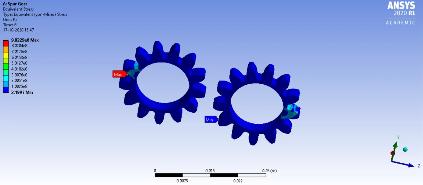
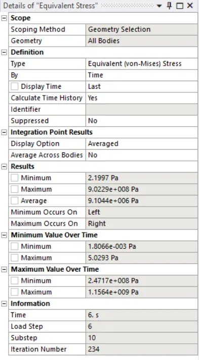
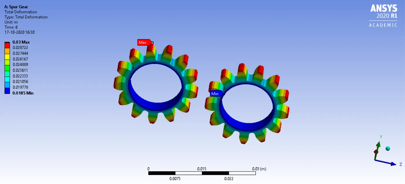
Total Deformation
Stress Intensity
Case 2
For case 2, the material used was Cast Steel of ductile nature.
For the solution, equivalent stress or von-missus stress, total deformation, stress intensity was inserted.
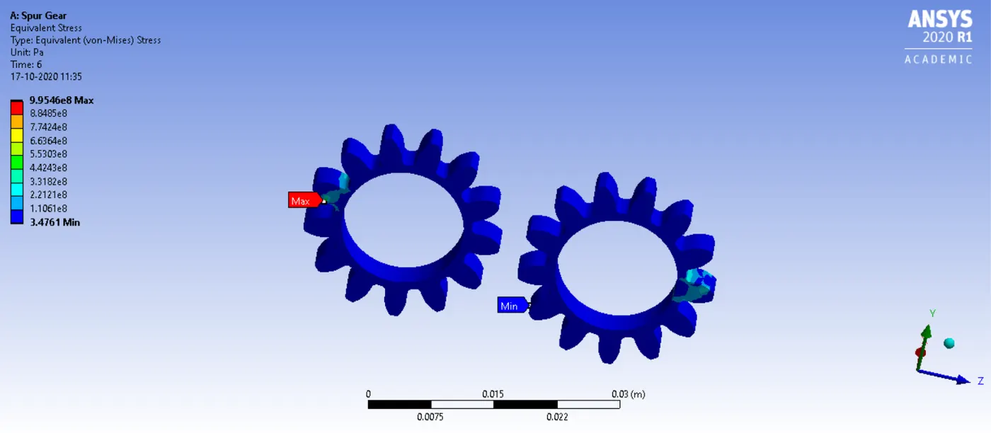
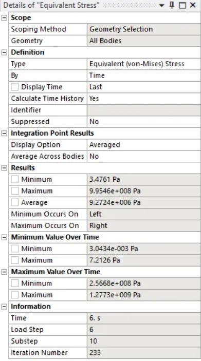
The maximum and minimum values for these boundary conditions have been mentioned below.
|
Boundary Conditions |
Maximum Value |
Minimum Value |
|
Von-Missus Stress |
9.9546e8 Pa |
3.4761 Pa |
|
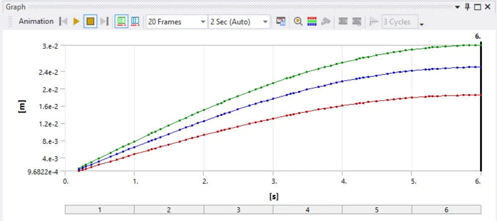
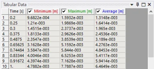
Total Deformation |
0.3 m |
0.085 m |
|
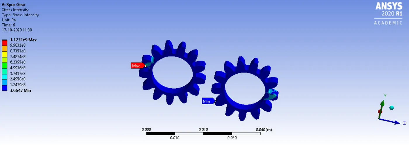
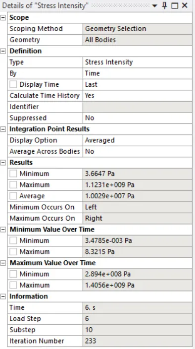
Stress Intensity |
1.1231e9 Pa |
3.6647 Pa |
Equivalent (Von - Missus Stress)
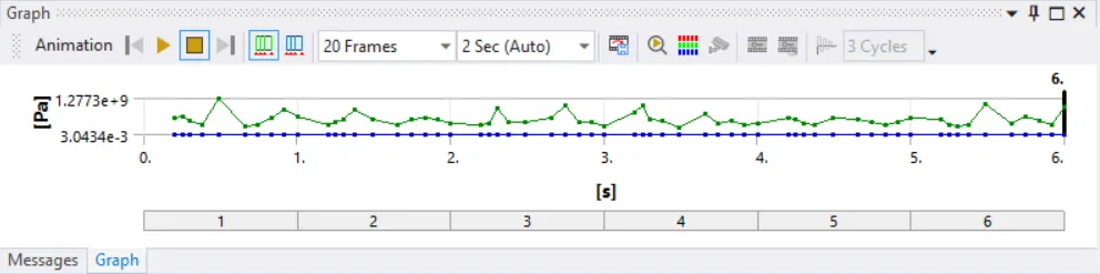
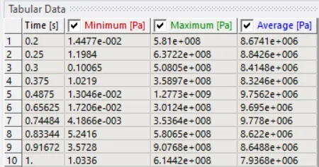
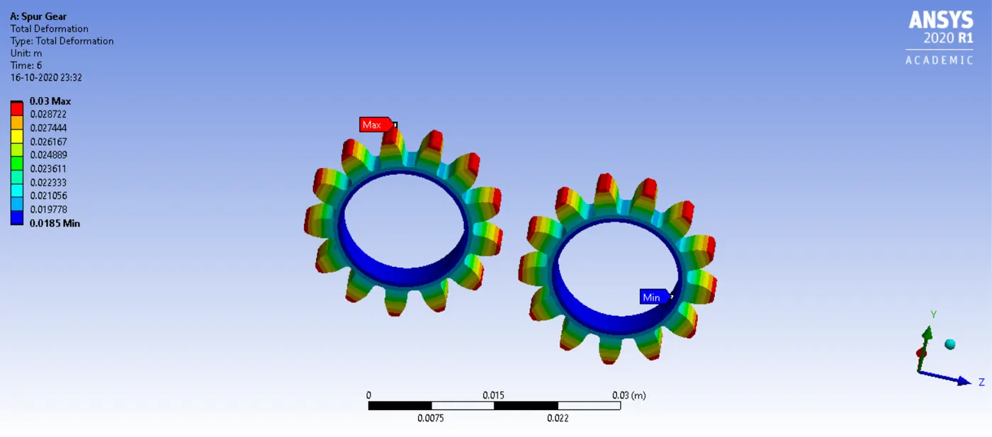
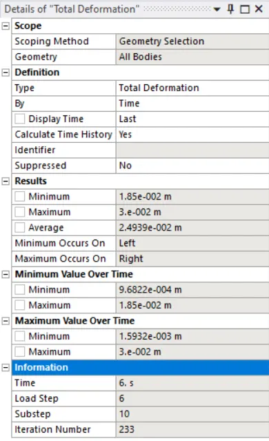
Total Deformation
Stress Intensity
Case 3
For the third case, the material used was cast bronze.
For the solution, equivalent stress or von-missus stress, total deformation, stress intensity were inserted.
The maximum and minimum values for these boundary conditions have been mentioned below.
|
Boundary Conditions |
Maximum Value |
Minimum Value |
|
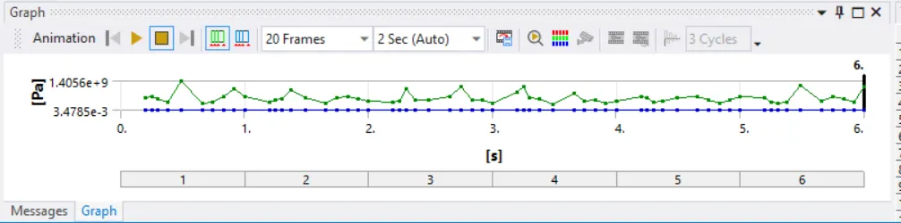
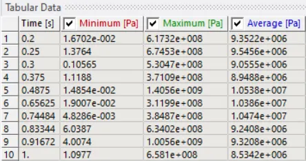
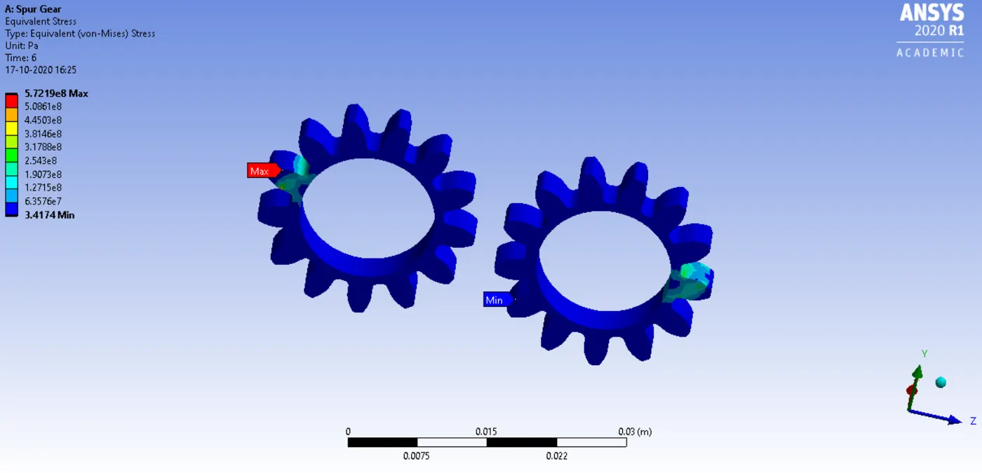
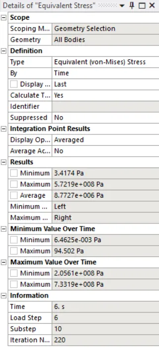
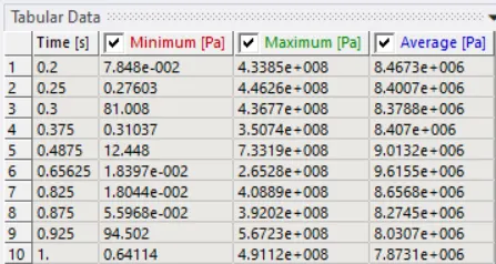
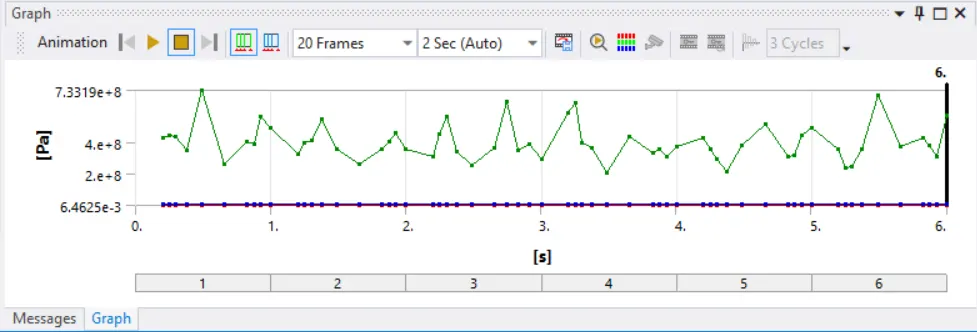
Von-missus stress |
5.7219e8 Pa |
3.4174 Pa |
|
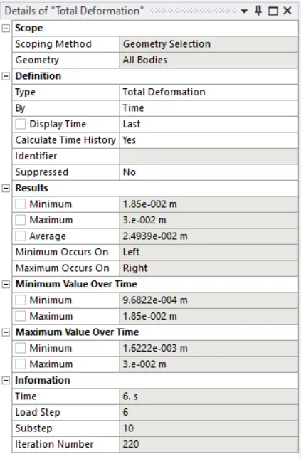
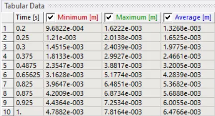
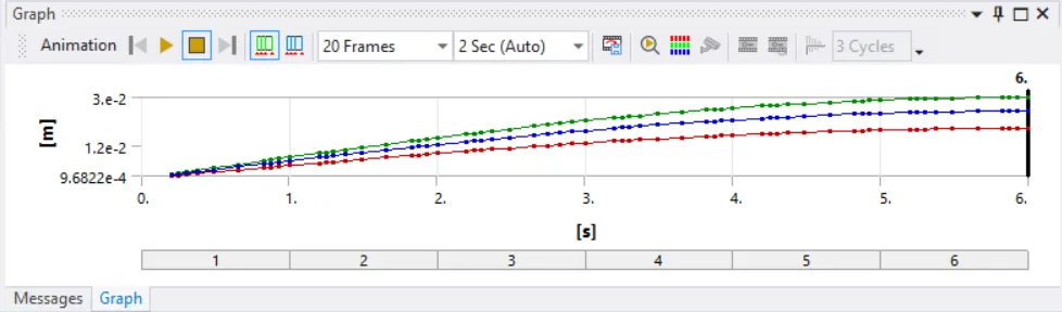
Total Deformation |
0.03 m |
0.185 m |
|
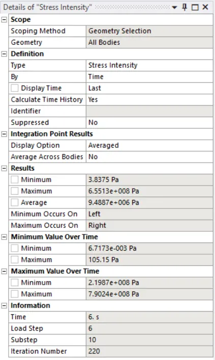
Stress Intensity |
6.5513e8 Pa |
3.8375 Pa |
Equivalent (Von-Missus) Stress
Total Deformation
Stress Intensity
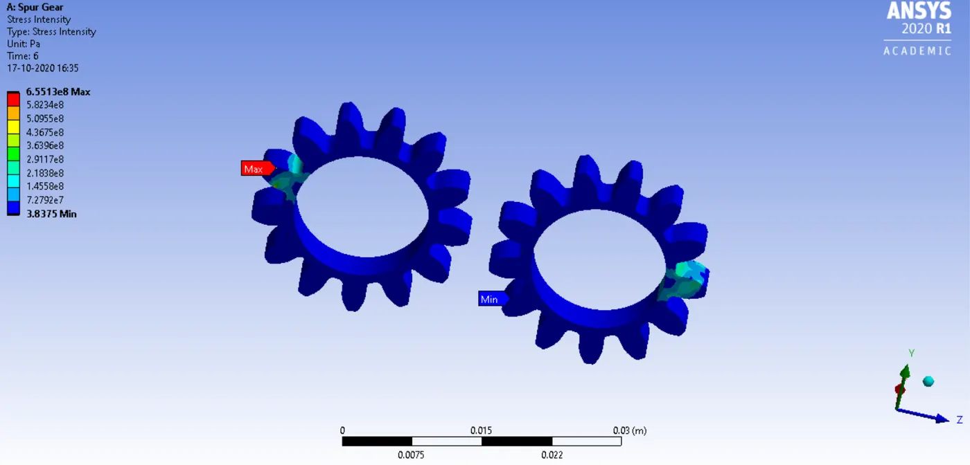
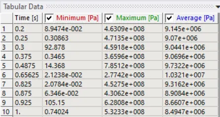
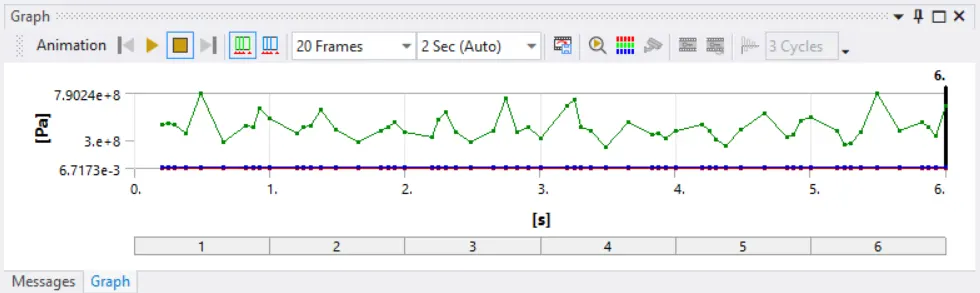
For all three cases, the point of fracture would be at the site where the intensity of stress is maximum thereby resulting in maximum deformation.
OBJECTIVE 2
Based on the above analysis, a comparison between the three cases was made. According to this comparison, it was found out that if the spur gear was made was Cast Bronze, then it would be the most suitable. The reason for this is that in the case of this material and the equivalent stress or von-missus stress and the stress intensity is comparatively less as compared to all the other materials used although the maximum and minimum values for total deformation do not differ much.
The videos of the total deformation, equivalent stress or von-missus stress, and the stress intensity have been attached below.