Week 1 Spur Gear Challenge
AIM: - CARRY OUT A DETAILED STATIC ANALYSIS OF THE GIVEN SPUR GEAR MODEL TO FIND OUT EQUIVALENT STRESS, TOTAL DEFORMATION, AND STRESS INTENSITY FOR THREE DIFFERENT MATERIALS.
Objective: - Compare the results of all the cases and conclude which material must be recommended.
Spur Gears are the most basic gears, with the gear tooth being parallel to the axis of the gear. These gears are used in low to medium-range load applications. The spur gears create a lot of noise during the mating process, as a result, despite these gears being free from axial thrusts, the helical gears (gear tooth inclined to the gear axis) are predominantly used.
Stress Intensity: -
Stress intensity is a concept that is used to determine the stress concentration (or the state of stress) near the tip of a crack or notch.
The Stress Intensity Factor (K) is very useful in providing the failure criteria for the brittle materials.
The Stress Intensity Factor depends upon the size of the crack, location of the crack, the geometry of the component, and the applied load and its distribution.
Mathematically, the Stress Intensity Factor is written as:
K = σ .f(a/W)
Where
f(a/W) = geometry dependent function of the crack length (a) and width of specimen (W).
σ = Applied Stress.
The unit of the stress intensity factor is Stress.(Length)1/2.
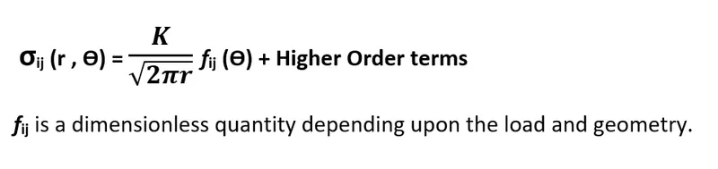
The stress distribution, predicted through the elastic theory, near the crack tip (in the polar coordinate system) is:
STEPS:
Start a new Static Structural project.
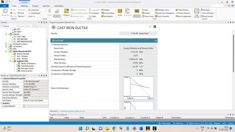
Go to Engineering Data, select the CAST IRON DUCTILE material, and click on the ADD to add the material to the project.
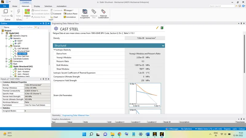
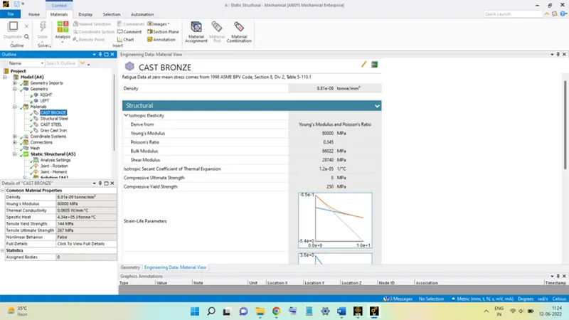
The other two materials, if not present in the Engineering Data Sources, must be manually added to the project. The properties of the two materials are added from the data supplied in the problem.
The materials' properties are mentioned in the figure below:
CAST IRON DUCTILE:
CAST STEEL:
CAST BRONZE:
Rename the two gears as LEFT and RIGHT to the respective gears:
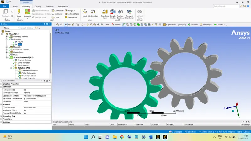
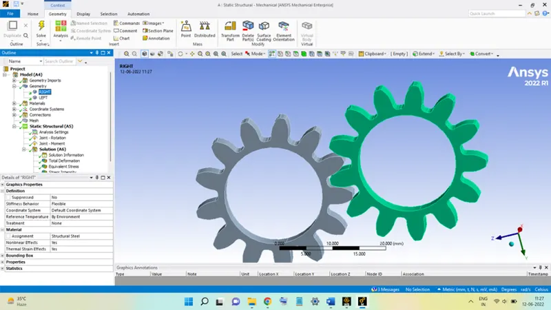
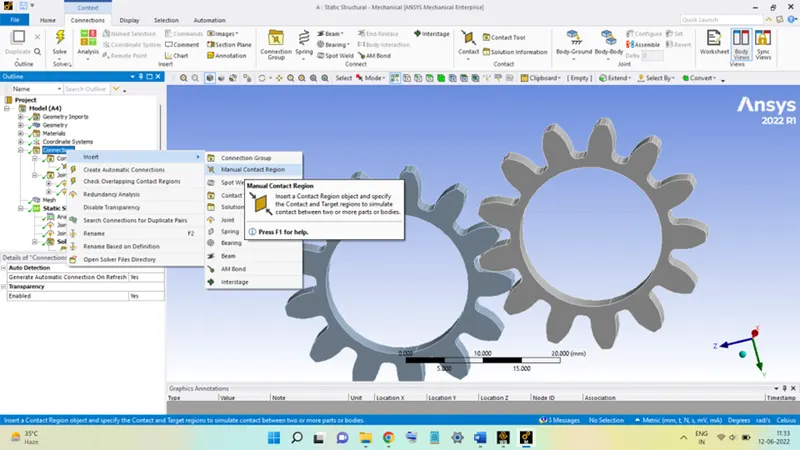
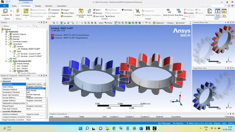
The next step is to determine the type of contact between the gear teeth of the two mating gears. This is done by right-clicking on Connections, then going to Insert, and then selecting the option Manual Contact Regions.
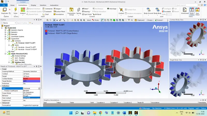
Select all 26 gear faces of the RIGHT gear, which is taken as the Contact Body, and then the 26 gear faces of the LEFT gear acting as the Target Body.
Then select Frictional in the Type option.
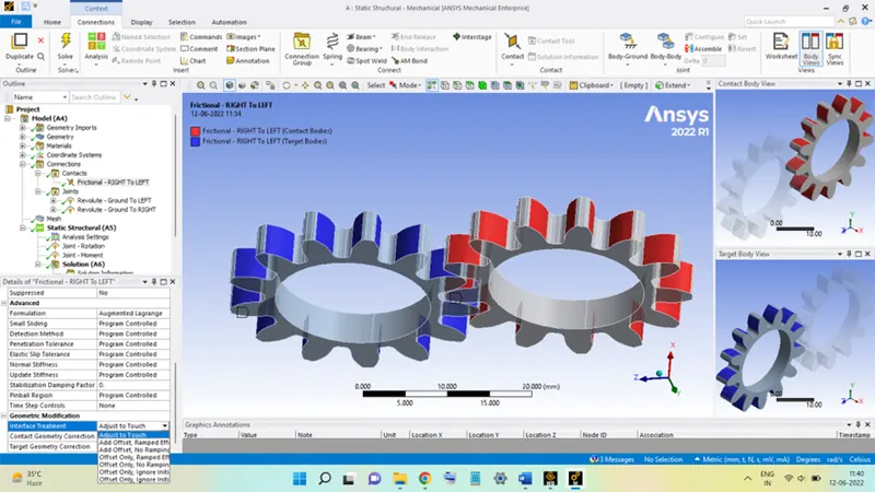
Next, go to Formulation and choose Augmented Lagrange, after this go to the Interface Treatment option and select Adjust to touch option.
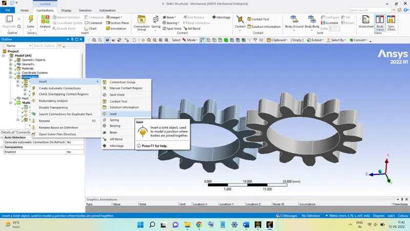
The next step is to determine the type of joint present in the model. The gears are having a revolute joint with the ground.
To add this to the model, right-click on the Connections, go to Insert, and choose the option Joint.
Now, define the Connection type as Body-Ground.
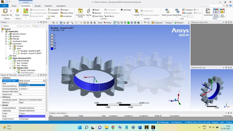
And select the inner faces of the gear and hit Apply.
Perform the same for the other gear also.
The next step is to generate the mesh, this is done by clicking on Mesh and then setting the Element Size equal to 0.75 mm. further, in the Sizing section, select NO in the Use Adaptive Sizing. Then, in the Quality section, select Low in the Smoothing option. Then right-click and click on Generate Mesh to start the meshing operation.
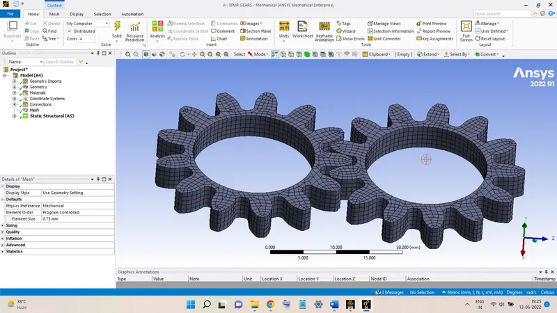
After this, the next step is to click on Analysis Settings. Now, in the Step Controls section, enter the value of the Number of Steps as 6. Now near the bottom of the GUI the 6 timesteps will be generated, select all timesteps, to apply settings on them.
Turn the Auto Time Stepping option ON.
Select Time in the Define By option.
Turn the Carry Over Time Step option OFF.
Set the Initial Time Step as 0.2 sec.
The minimum Time Step as 0.05 sec and the Maximum Time Step as 0.5 sec.
In the Solver Controls section, turn the Large Deflection option ON.
The next step is to supply the Joint Load to the model. This is done by right-clicking on Analysis Settings, then going to Insert and selecting the option Joint Load.
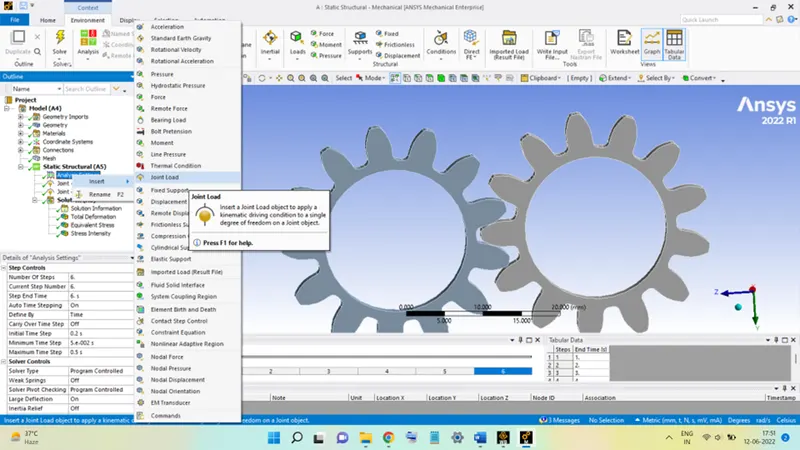
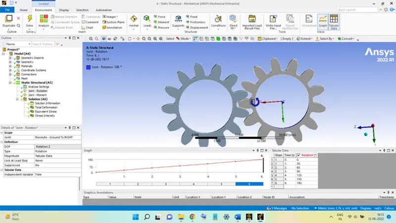
After that, select the joint Ground to RIGHT, then in the Definition section choose Rotation under the Type option. Next, in the Magnitude option select Tabular Data.
In the table, shown in the bottom region, enter the value of rotation occurring in each time step, as shown in the figure below:
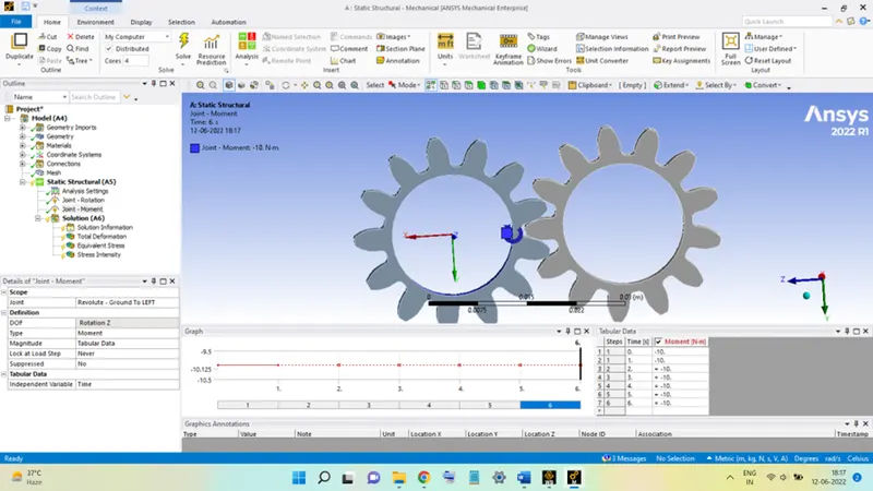
In the same way, select the second joint, but for this one, the Type is set to Moment and the rest remains the same. In the table enter the magnitude of the moment equal to -10 N-m for all the time steps.
Now the last step is to add the necessary results needed for the comparison. This is done by right-clicking on Solution, then going to Insert, and then to Deformation and selecting the Total option. Similarly, in the Stress option, select the Equivalent to add Equivalent Stress and then select Intensity to add Stress Intensity into the solution.
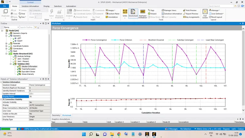
With this the model is ready for the analysis, click on the Solve button to begin the solution process. The solver will then start the analysis and after some time the results will be obtained. The Force Convergence graph during the execution of the analysis is shown below:
After successful completion of analysis for the Cast Iron Ductile, the material assignment is changed and the analysis is re-run for the new material until results for all materials are obtained.
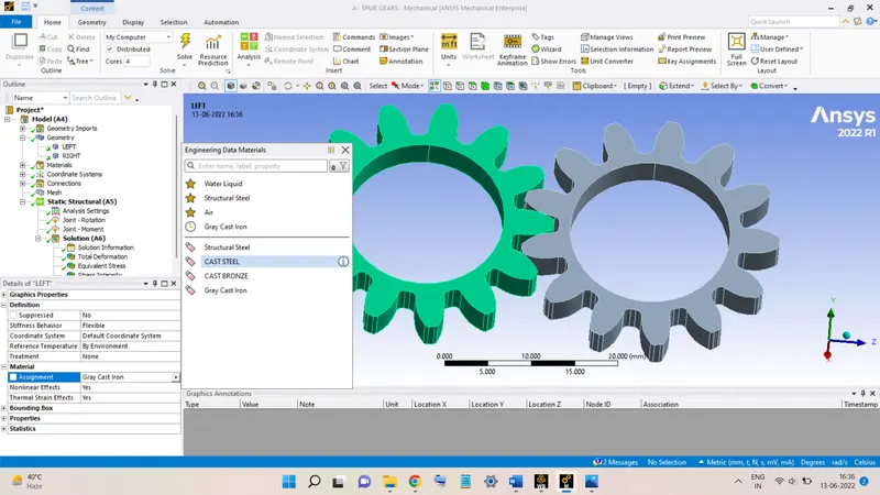
Material assignment can be changed by clicking on Geometry and selecting the LEFT gear and then in the Materials section go to Assignment and change the material from CAST IRON DUCTILE to CAST STEEL. Similarly, do the same for the RIGHT gear and the rest of things remain the same and the analysis is performed. The same thing is done to change the material to CAST BRONZE.
RESULTS
1. CAST IRON DUCTILE:
a) Equivalent Stress:
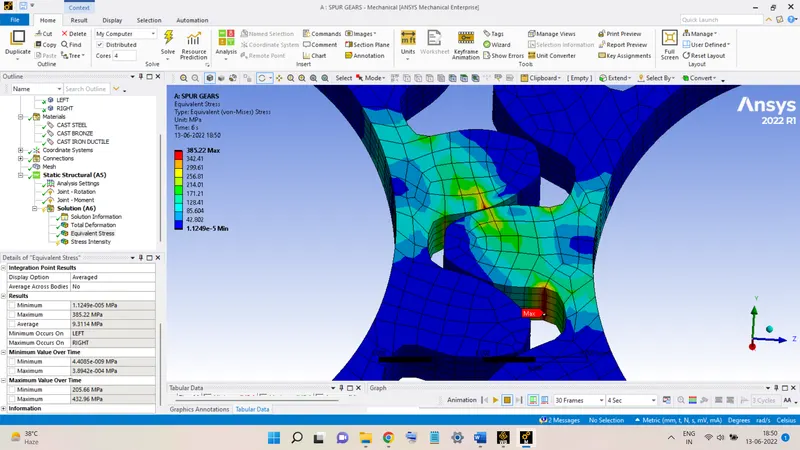
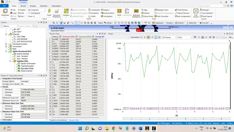
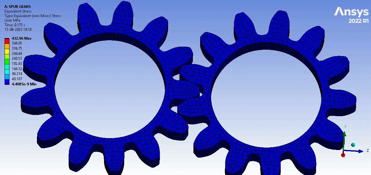
From the figures shown above, it is seen that the maximum stress is induced near the root of the gear tooth.
The maximum value of the stress is equal to 432.96 MPa.
Stress Intensity:
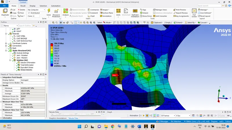
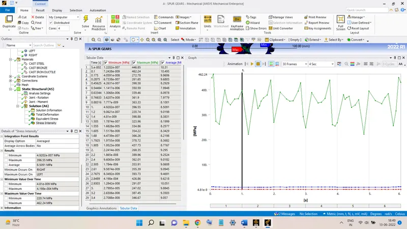
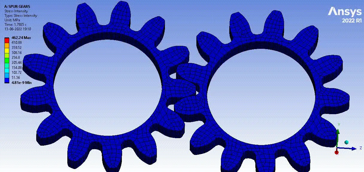
The above figures show the maximum stress intensity regions in the following spur gear model, which is the same area experiencing the maximum stress.
The maximum stress intensity value is 462.24 MPa near the root of the gear tooth.
Thus, it can be said that the root of the gear tooth is most prone to fracture.
Total Deformation:
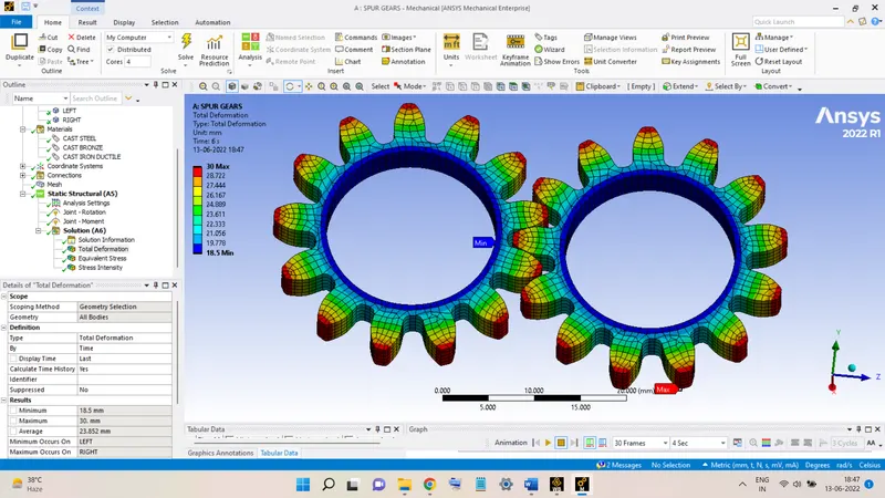
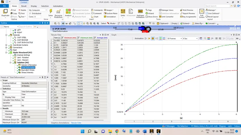
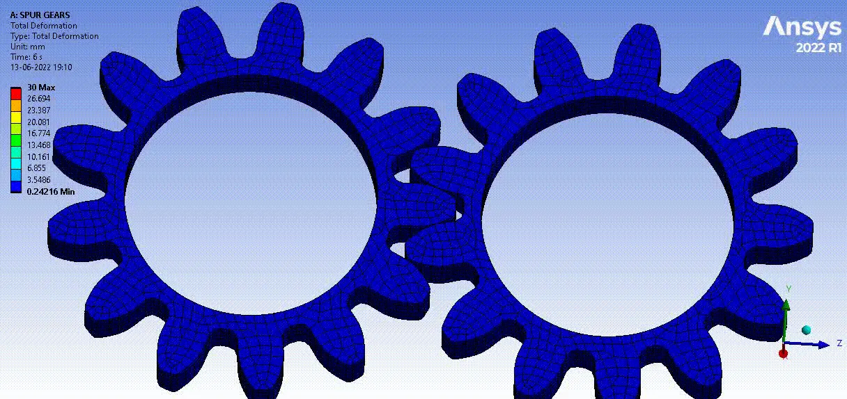
The above figures show the total deformation occurring in the given model, the maximum value being equal to 30 mm.
2. CAST STEEL:
Equivalent Stress:
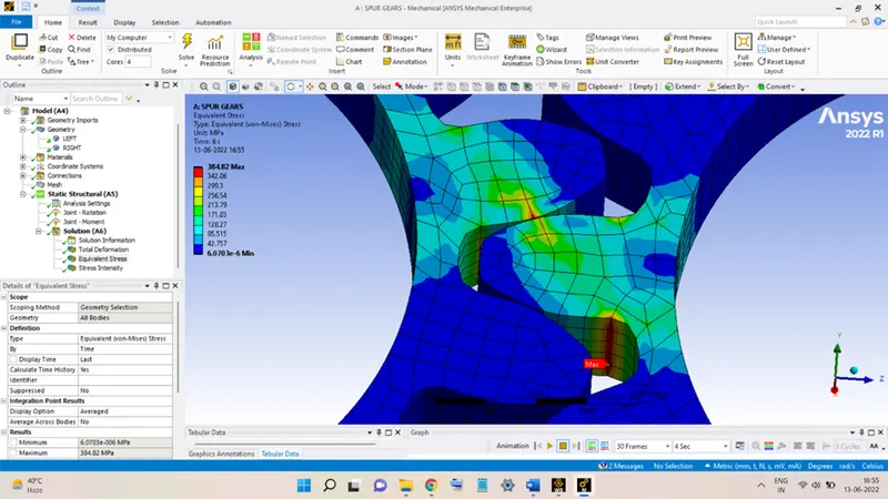
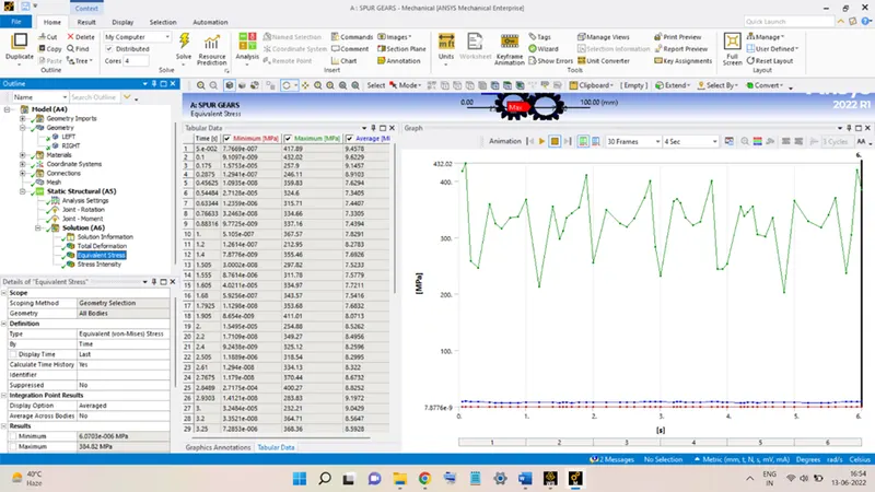
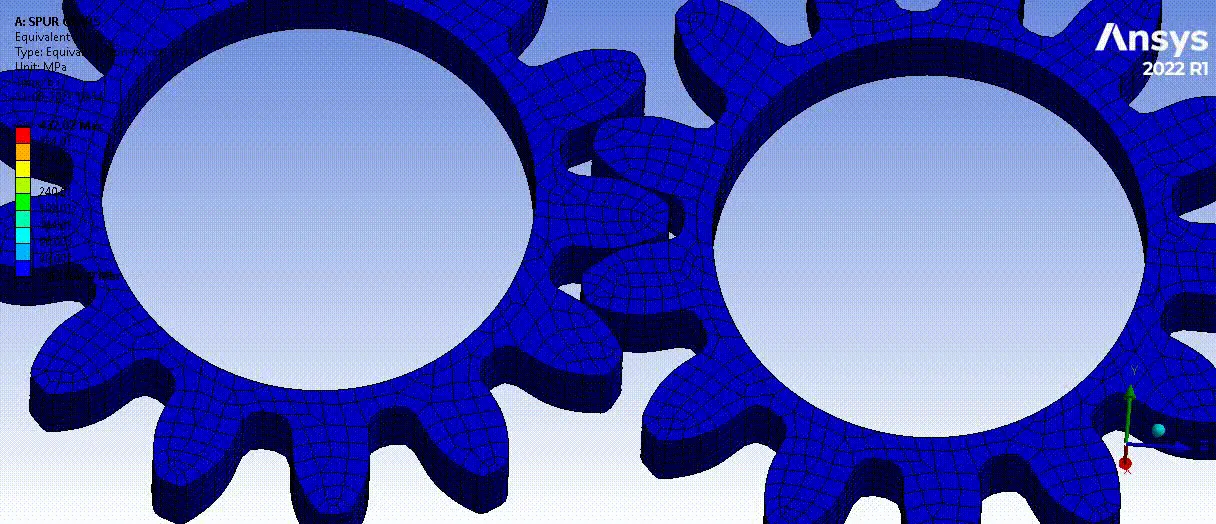
The maximum value of the stress is equal to 432.02 MPa.
Stress Intensity:
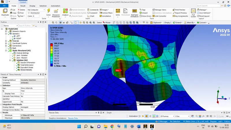
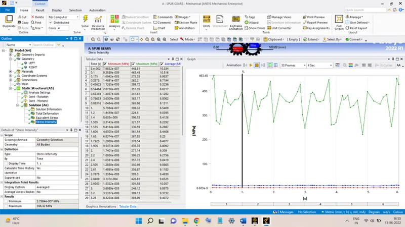
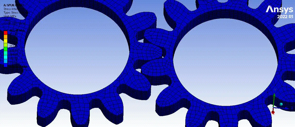
The maximum stress intensity value is 463.48 MPa near the root of the gear tooth.
Total Deformation:
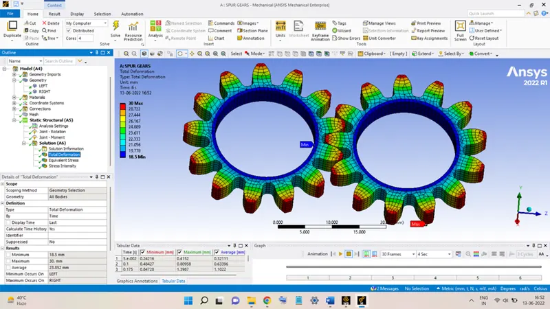
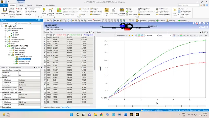
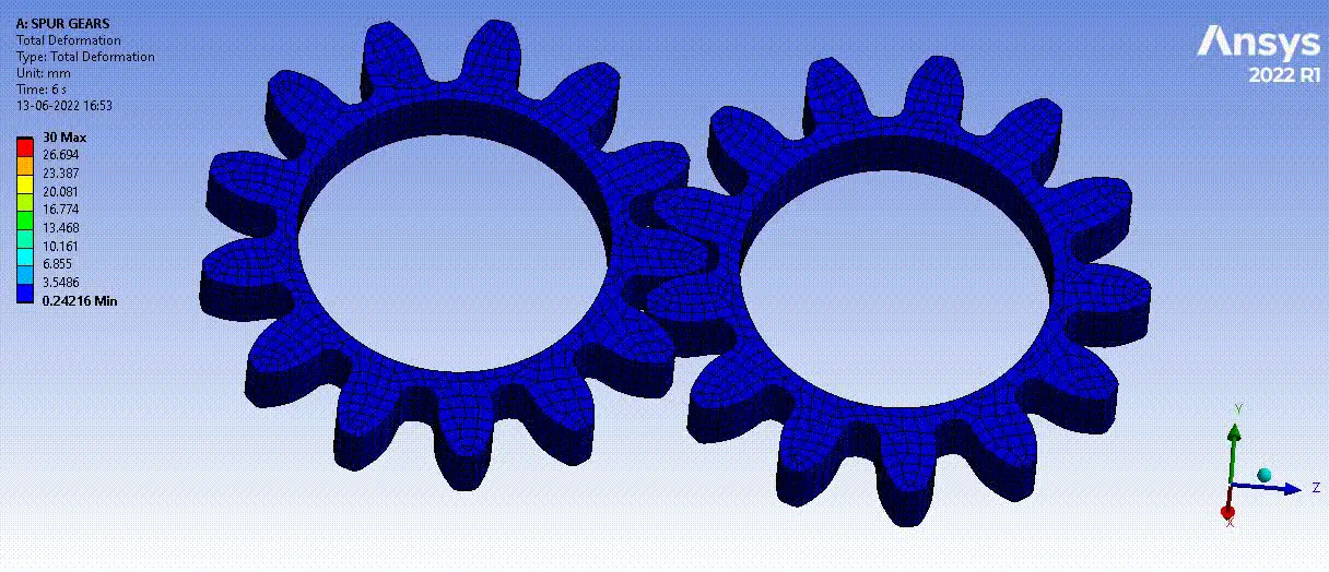
The above figures show the total deformation occurring in the given model, the maximum value being equal to 30 mm.
CAST BRONZE:
Equivalent Stress:
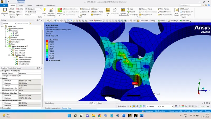
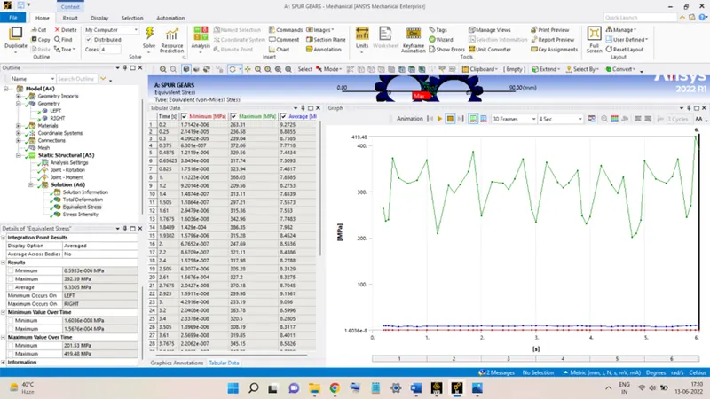
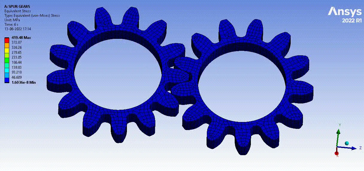
The maximum value of the stress is equal to 419.48 MPa.
Stress Intensity:
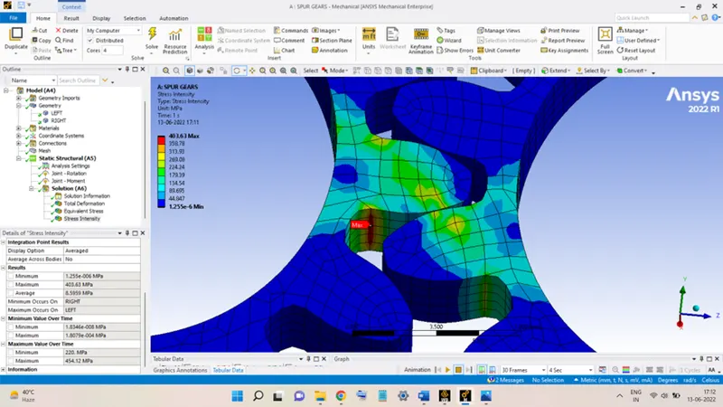
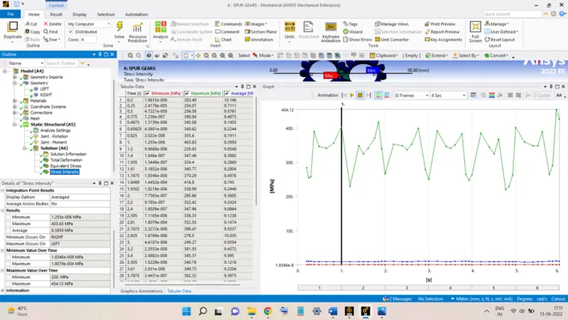
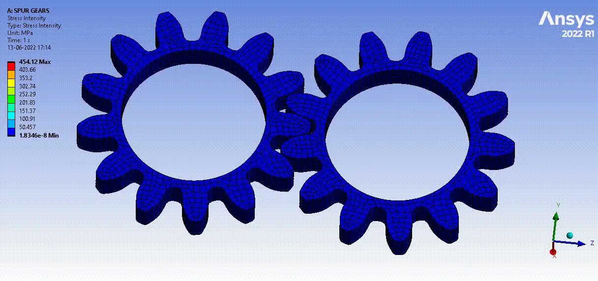
The maximum value of the stress intensity is equal to 454.12 MPa.
Total Deformation:
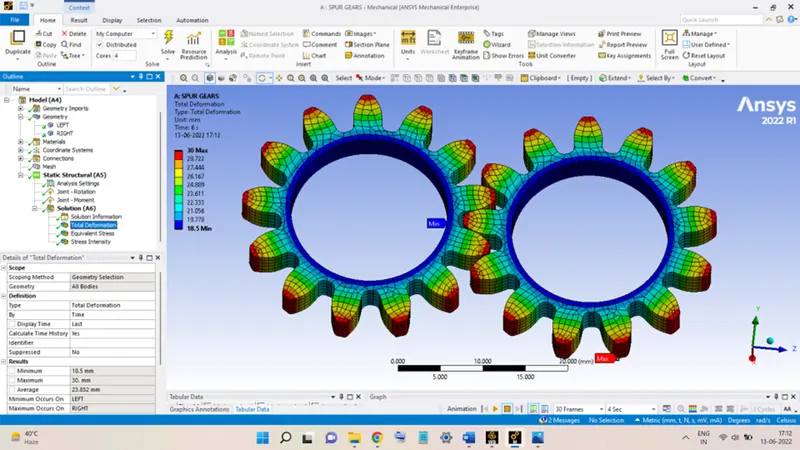
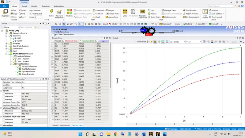
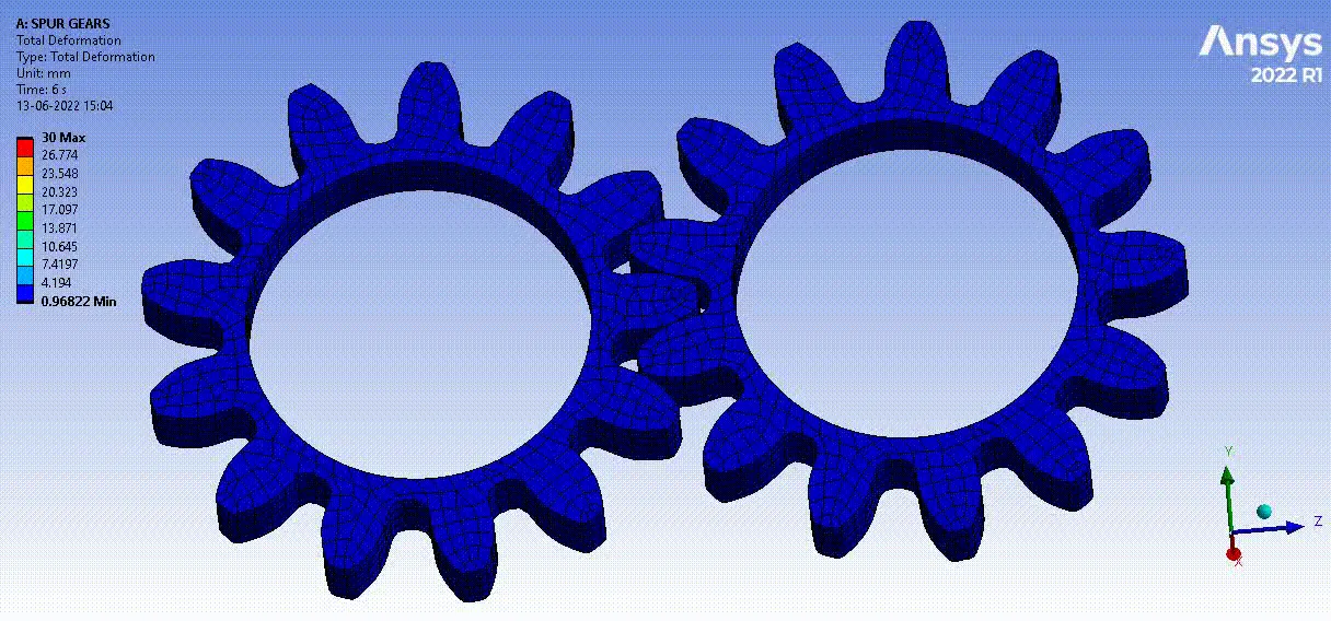
The above figures show the total deformation occurring in the given model, the maximum value being equal to 30 mm.
Comparison:
|
|
MAX. EQUIVALENT STRESS (MPa) |
MAX. STRESS INTENSITY FACTOR (MPa) |
TOTAL DEFORMATION (mm) |
|
GRAY CAST IRON |
432.96 |
462.24 |
30 |
|
CAST STEEL |
432.02 |
463.48 |
30 |
|
CAST BRONZE |
419.48 |
454.12 |
30 |
From the above table, it can be seen that:
The maximum value of the equivalent stress induced in gears for Cast Iron and Cast Steel is almost the same and both have stress higher than that induced for the Cast Bronze material.
Cast Bronze has the least stress value and Cast Steel have the maximum stress intensity factor value among the three.
In all cases, the maximum stress intensity actor was found at the root of the gear tooth. So, the spur gear is prone to fracture in that area.
Out of the three materials, the highest stress intensity factor value is obtained for the Cast Steel spur gear. Hence, it can be said that the Cast Steel spur gears are most likely to fracture at the root of the gear tooth out of the given materials.
On comparing the above results, it can be said that the most suitable material for the spur gear, according to the results of the Static Analysis performed for the three different materials, is CAST BRONZE.