Week 1 Spur Gear Challenge
Objective: -
1.Perform static structural analysis on spur gears and find out the Equivalent stress, Total deformation and Stress intensity using
i. Cast Steel
ii. Cast Bronze
iii. Cast Iron
2.Which material will we choose for manufacturing of spur gears based on these results.
3.Find out the location for possible fracture.
Procedure:
• Open the Ansys workbench and drag and drop the static structural analysis system in the project schematic Rename the project as "spur gear analysis".
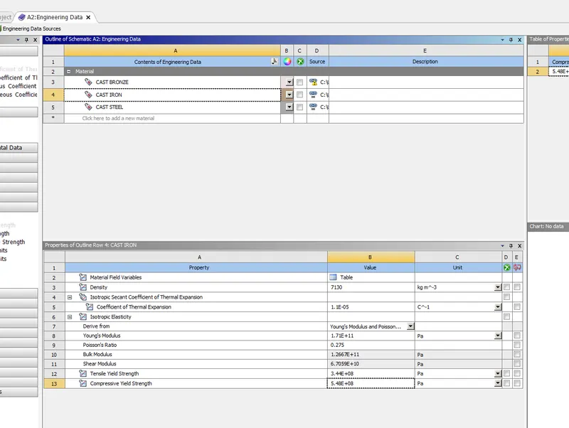
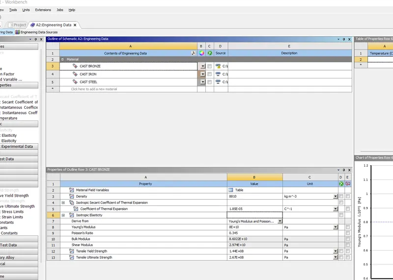
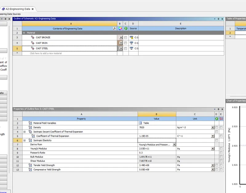
• Double click on engineering data to add the material or we can click right mouse botton and choose edit option from the drop down menu.Simply click in "contents of engineering data" to add material and choose the properties of the material from the toolbox. Then, We have to manually feed the data of the properties.
CAST IRON
CAST BRONZE
CAST STEEL
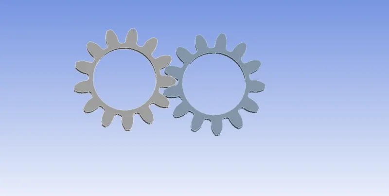
• We have to import the "spur gear" model by clicking the right mouse button and choose the import geometry option.
• Double click on the model component to open ansys mechanical.
. Select the particular geometry and select the required material from the material assignment option.
CONNECTIONS -
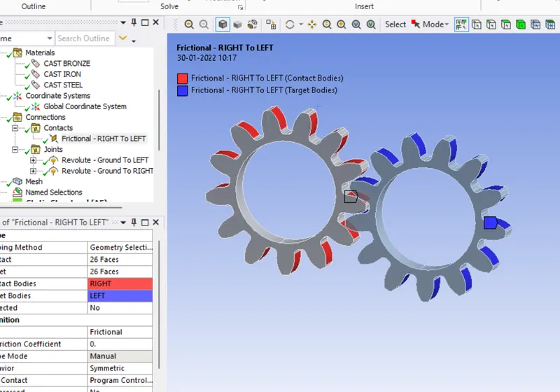
• Go to connections>scope>contacts and select those 26 faces of left spur gear that will be in contact with right spur gear. Select the target faces of the right spur gear. Put contact type as frictional, behaviour as symmetric.
• Formulation is used to define the behaviour of contacts that we specify. Augmented lagrange increases the stiffness and thus reduces the penetration and chattering of the model.
MESHING -
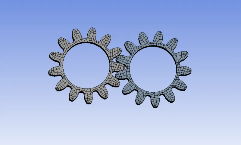
. We used element size as 1mm to get more accurate results. Use adaptive sizing as 'no', and smoothing as low. Smoothing helps to improve the element quality by moving the location of nodes with respect to the surrounding nodes. The low option controls the number of smoothing iterations.
ANALYSIS SETTINGS -
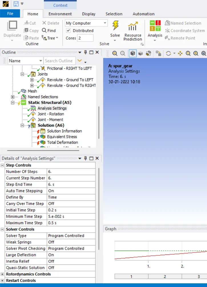
• In a static analysis where it is time-independent, the analysis takes place as steps in which the steps are incremented linearly. • Auto time-stepping helps in optimizing the load steps for reducing the solution time. The load increment range in a simulation for auto time stepping depends on the values inputted by the user. The solution, as usual, will start from the 'initial' increment value. The automatic stepping will vary between the values given by the user in the maximum and minimum options.
• initial time step-0.2
minimum time step-5E-2
• maximum time step-0.5
Enabling large deflection by ON will help the solver to consider the large strain happening, such as metal forming in a simulation and deflection.
JOINTS -
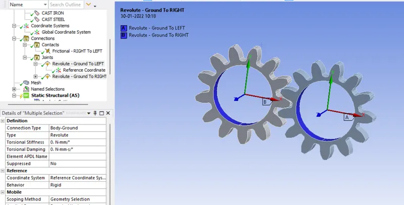
• A Revolute joint between the ground to the left and right spur gears. Provide rotation to the right spur gear and moment to the left spur gear.We can feed the data for rotation in a tabular manner.Put the interval of 30 degrees for rotation. • Insert the value for momemt as -10000 N-mm. The negative sign indicates the clockwise rotation of the gear.
SOLUTION
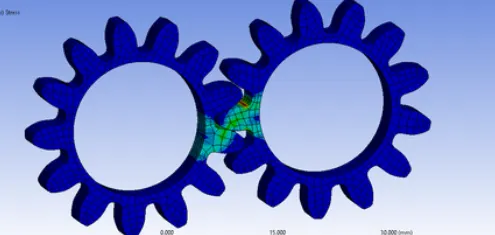
VAN STRESS FOR CAST STEEL
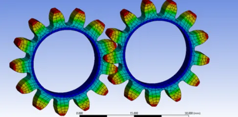
TOTAL DEFORMATION FOR CAST STEEL
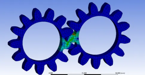
STRESS INTENSITY FOR CAST STEEL
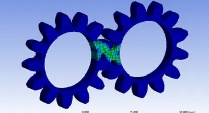
VAN STRESS FOR CAST BRONZE
TOTAL DEFROMATION FOR CAST BRONZE
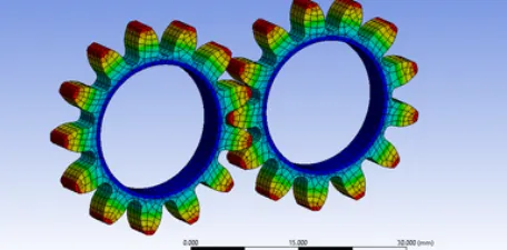
VAN STRESS FOR CAST IRON
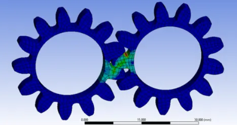
TOTAL DEFORMATION FOR CAST IRON
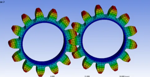
CONCLUSION: -
• The above analysis suggests that the maximum stress will develope in cast steel(387.67), then in cast iron(381.4) and minimum in cast bronze (361.4).
. The total deformation remains same for all the three cases.
• Cast Steel will also experience high stress intensity then Bronze and iron.
Calculating the factor of safety for all the three materials we will get the highest FOS for cast iron i.e 1.43. So, we will choose Cast iron as manufacturing material for the Spur gear.