Week 1:- Introduction to BiW and Fixtures Challenge
1) What is BIW and its parts?
BIW
- BIW is abbreviated as Body In White.
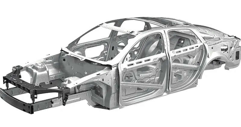
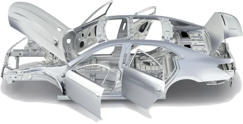
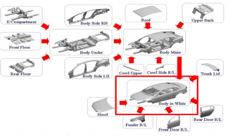
- In the Automotive Industry BIW (Body in White) is the common terminology used to mention the car sheet metal welded structure (body shell).
- Automotive car shell made before painting is called Body in White.
- BIW refers to the welded sheet metal components which forms the vehicle structures to which the other components like Engine, Chasis, Exterior and Interior trims will be assembled or married.
- In today's situation, automotive BIW is made of steel (various steel grade material -DP, DD, HDP etc.) as well as made of aluminium alloy (e.g. AUDI A8) with thickness ranging from 0.7- 2.0 mm.
- Sub-assemblies like Under body, Body side Left Hand Side/ Right Hand Side, Front End, Roof etc. gets welded together by various metal joining process e.g. resistance spot welding, Laser welding, MIG welding to make welded metal shell (Without Door, Trunk-lid / Tailgate) , Fender, Bonnet Center) called Body in White.
- BIW encloses protects the passengers and carges. The BIW design needs to be stiff to support the mass and securely keep them all integrated.
- Further, it needs to resist & absorb energy during the event of vehicle crash.
- BIW design also needs to be light weight structure so that there can be a possibility of reduced fuel consumption and increased Performance.
- BIW constitutes about 27 % of a car’s weight.
MAJOR INFLUENCING FACTORS OF BIW DESIGN
- Number of Parts.
- Materials
- Internal structural reinforcements.
PRINCIPLES CONSIDERED IN BIW DESIGNS:
- Effective load paths in the BIW architecture with minimum number of components in the design.
- Material distribution in the BIW considering the bending and torsion stiffness of the BIW
- Internal Reinforcements location which could lead to efficient performance increase.
- Material Optimization method on a full vehicle crash analysis.
TYPES OF BODY STRUCTURES:
1). MONOCODE BODY STRUCTURE:
- The term monocoque means the chassis integrates with the complete body as one part. It is a French term that means 'single shell' or 'single hull. ' Monocoque construction is significant for reducing the vehicle's overall weight by integrating the chassis and the body into a single unit.
- A Monocoque is a shell around the car made by using both chasis as the frame in a single construction.
- Wheels are directly mounted to the BIW with the help of suspension system.
- This is the most commonly used chasis body structure.
2). BODY-ON-FRAME BODY STRUCTURE
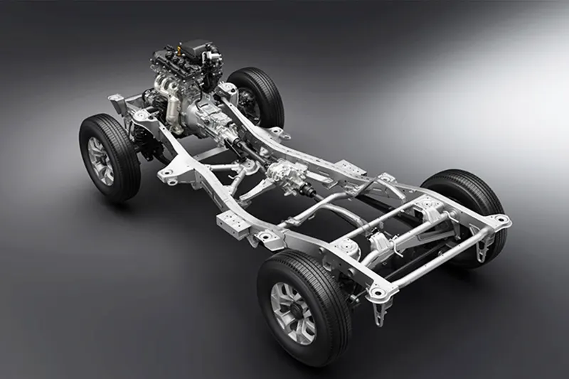
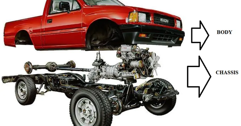
- Body-on-frame is a common motor vehicle construction method, whereby a separate body or coach is mounted on a strong and relatively rigid vehicle frame or chassis that carries the powertrain (the engine and drivetrain) and to which the wheels and their suspension, brakes, and steering are mounted.
- Body-on-Frame constructions is now used mainly for heavy trucks, pickups and predominantly large SUVs.
PARTS OF BIW
BODY SIDE PANELS
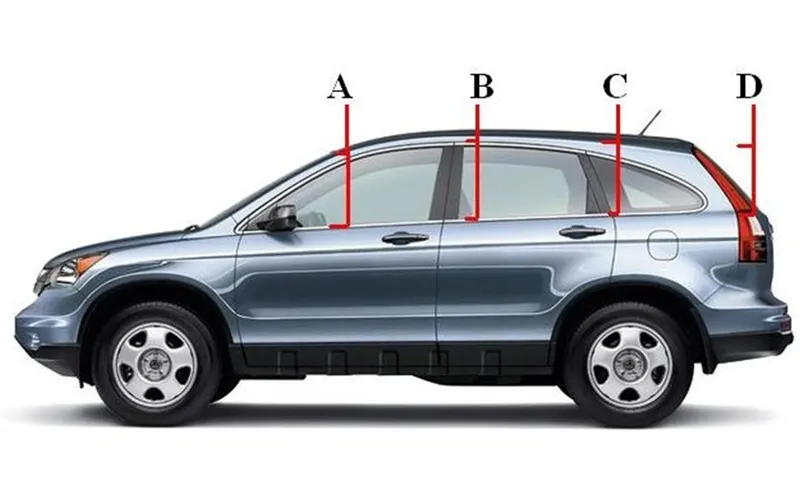
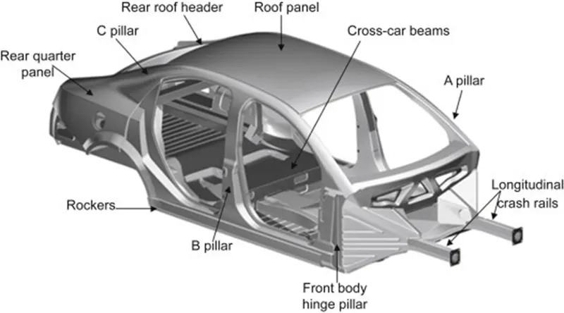
- A-PILLAR: Front most support to the roof.
- B-Pillar: Second Support to the roof. It plays a key role providing strength to a mid-section to a vehicle.
- C- Pillar: C is a rear most support to the roof. In case of two row seating systems, it will be the third one. C-Pillar is often the most heavily leveraged pillar from a styling perspective.
- D- Pillar: D is the Fourth support usually rear side of the quarter panel. D pillar is really the end of the line in many ways this pillar is designed for the necessity to house the rear door in a wagon or SUV.
- Ring panel: A structure panel connecting the rear and front portion.
- Quarter Panel: Rear most panel of a body side structure.
- Drip rails/ Gutters: An exposed channel applied to the roof over the side windows to direct water away from the windows.
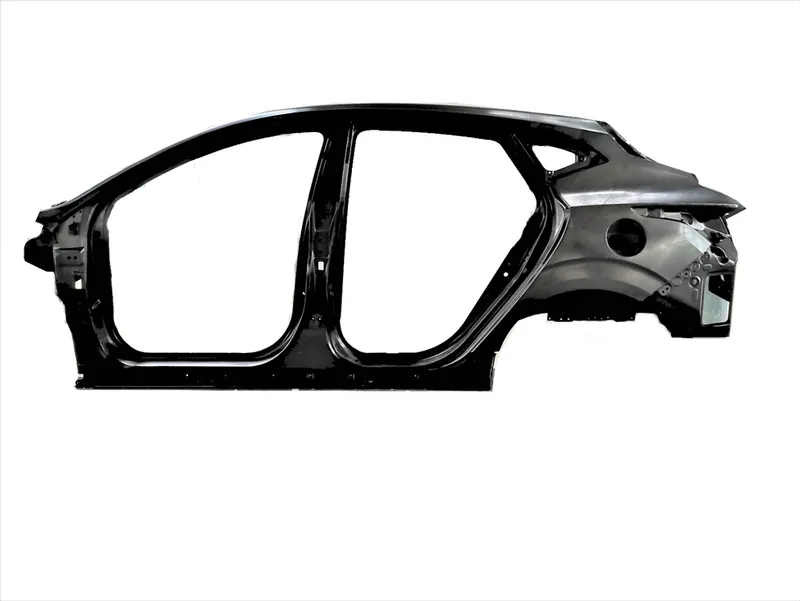
BODY SIDE OUTER:
- The outside panels proved the shape of the car body whereas the inner panels reinforce the sheel of the body.
- The various curved shapes are given to outer panels to provide the strength to panels.
- It includes A,B, C and D- Pillars, quarter panel, sill areas, etc.
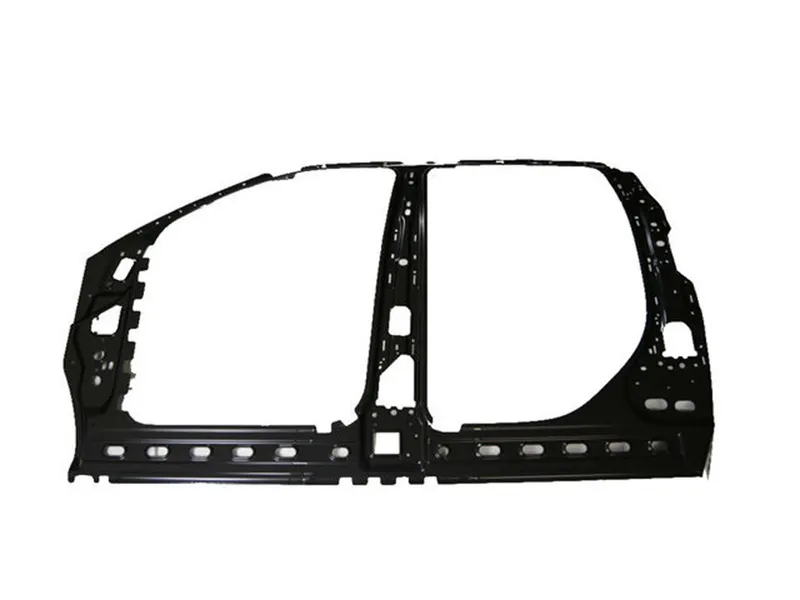
BODY SIDE INNER
- The inner panel provides mounting loactions for various trim panels and connecting assemblies.
- These two panels are welded together to pillars and rails so as to form the skeleton of the car body.
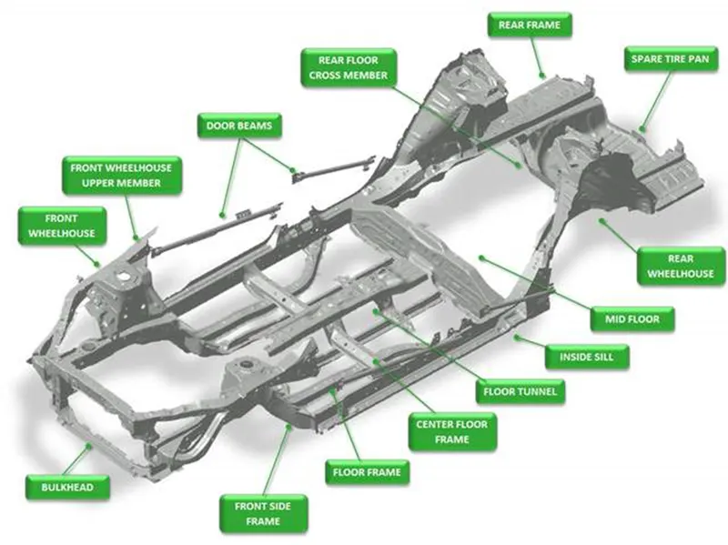
UNDERBODY:
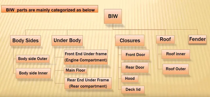
Underbody is the part of a moving vehicle that is underneath the main body of the vehicle. Underbody is further categorized into Front End Under Frame (Engine Compartment), Main Floor and Rear End Under Frame (Rear Compartment).
1). FRONT END UNDER FRAME (ENGINE COMPARTMENT)
It is an engine compartment area where all possible mounts for engine and other components get fixed.
- Plenum Panel: A chamber or a panel located between throttle body and runners of the intake manifold which is used to distribute the intake charge evenly and enhance engine breathing.
- FRT Wheel House (Fender): It is an encasement around the front wheel.
- Wing Panel: It is the outer most side panel in the front.
- Cowl: Cowl is the portion of the body bounded by the front fenders, the base of the windshield and the rear edge of the hood.
- Upper Tie Bar: It is the upper panel in front connecting the two sides such as Right side and Left side of front structure.
- Lower Tie Bar: It is the lower panel in front connecting the two sides such as Right side and Left side of front structure.
2). MAIN FLOOR
- Dash Panel: It provides partition between engine and the drive or passenger cabin inside car.
- FRT Floor: Front Floor provides a base for seats mounting and provides partition between transmission/propeller shaft/ground and the cabin.
- Riser: connects Front floor to Rear floor by providing a level difference.
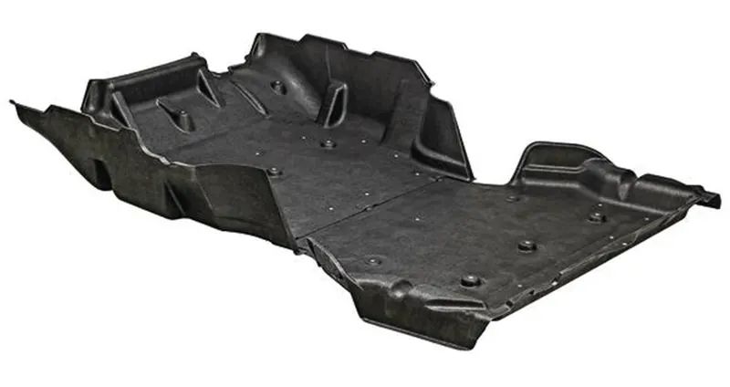
3) REAR END UNDER FRAME (REAR COMPARTMENT)
It is an area where spare wheel or stephney will be placed as well as other components and will have boot space.
CLOSURES
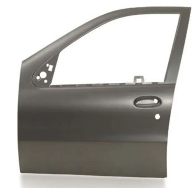
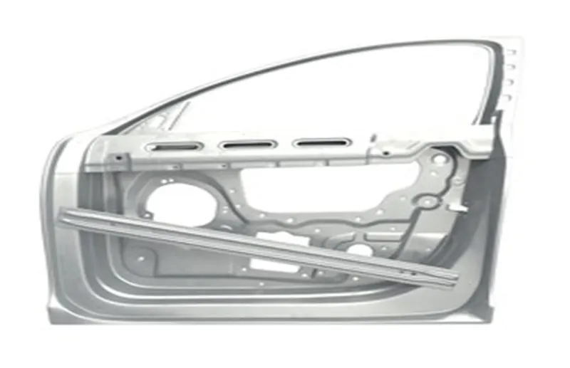
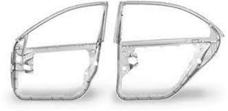
- Front and Rear Door
- There are side closures of cars to protect the passengers.
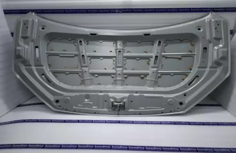
HOOD
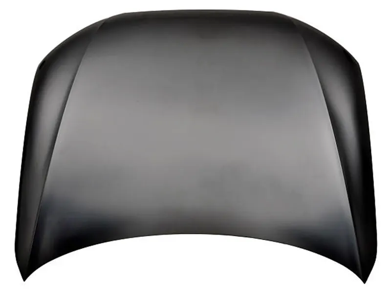
- Inner and Outer Panel
It covers the Engine compartment.
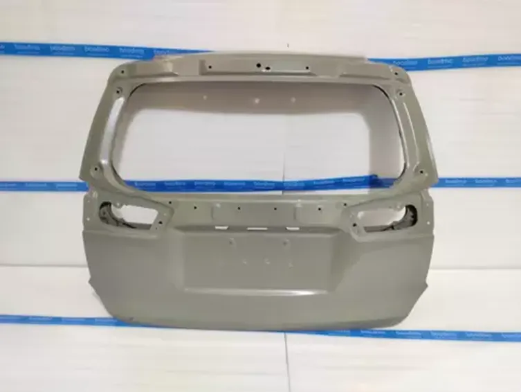
Decklid/ Backdoor/Tailgate:
It covers the boot space or rear compartment of the car.

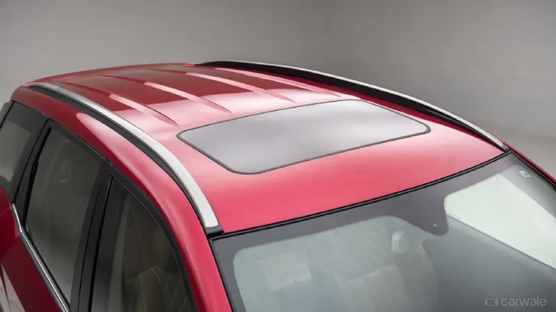
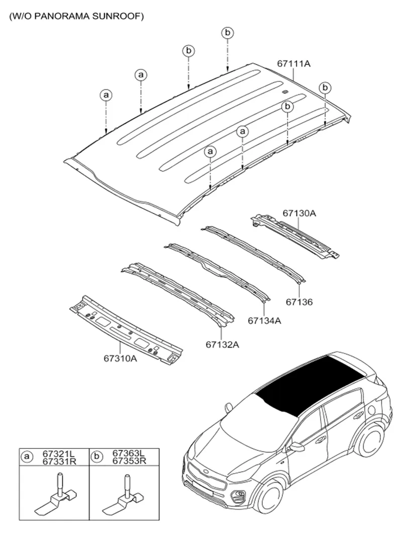
ROOF
INNER AND OUTER PANEL:
It covers the top of the car to protect from different weather conditions.
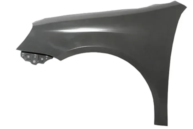
FENDER:
It covers the top of the front wheels.

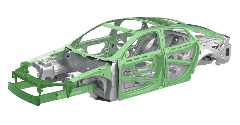
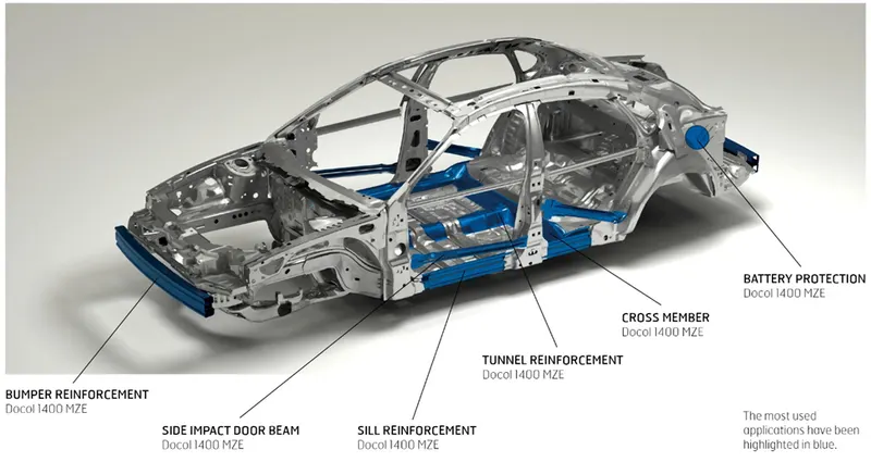
REINFORCEMENTS
- BIW reinforcements mount are evaluated through CAE studies for various crash sceneries such as high- speed frontal crashes, side impact, pole impact and rollover.
- The CAE studies performed using generic vehicle model, quantify the potential weight- savings in a vehicle by either replacing the existing reinforcements using a lighter system or by incorporating additional reinforcements in the BIW by down- gauging the existing BIW.
2) What do you understand by BIW Nomenclature?
BIW NOMENCLATURE
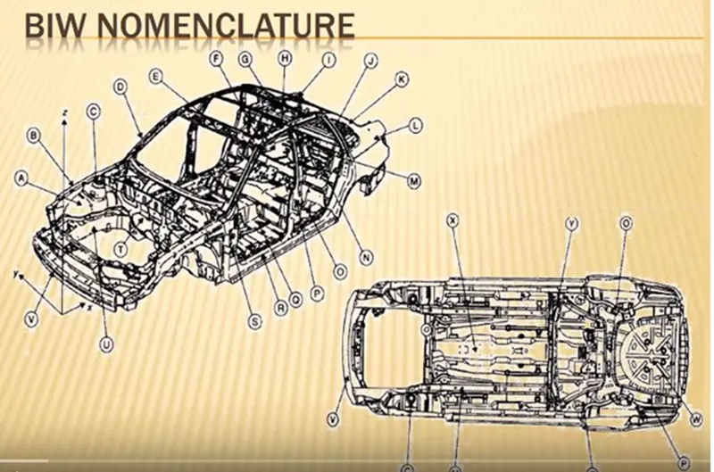
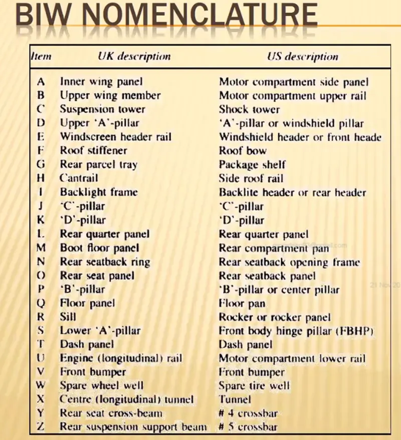
- Some BIW Nomenclature from UK and UK regions are mentioned above.
- Basically BIW Nomenclature is devising or choosing names for things.
- As, we know the BIW has many number of parts in it and all of them have different names.
- Automotive industry is spread worldwide and every nation has its own language. So, the every individual part of BIW have different name in different place or region.
3) What is Fixtures and its types?
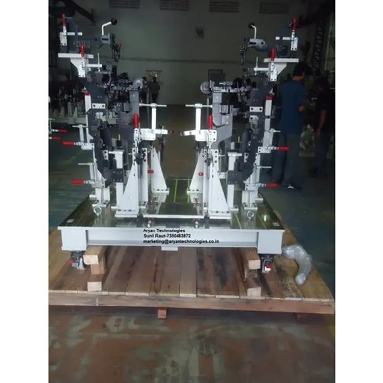
- A fixture is a device which holds the work piece to be processed (welded) by using 3-2-1 principle.
- A fixture is a work- holding or support device used in the manufacturing industry.
- Fixtures are used to securely locate (position in a specific location or orientation) and support the work, ensuring that all parts produced using the fixture will maintain conformity and interchangeability.
- In general a welding fixtures (tool) consist of number units together to hold car panel and is mounted on a base unit.
- Welding fixtures are normally designed to hold and support the various components (work piece) to be welded.
- It is necessary to support them in proper location which is capable of preventing distortions in work pieces during welding.
- For this the locating elements need to be placed carefully, clamping has to light but firm, placement of clamping elements has to be clear of the welding area and the fixtures has to be quite stable and rigid to withstand the stresses generated during welding process.
TYPES OF FIXTURES:
- Pre-Production fixture.
- Production fixture.
- Checking fixture.
PRE- PRODUCTION OPEARTION (PPO) FIXTURE:
- These fixtures are designed as the prototype fixture to check and study the feasibility of initial batch production.
- This type of fixtures are used to take the trial and errors from the components.
- While in trial and error, these errors are absorbed and corrections are made till the part/components attains its requirements as per the drawings.
- We have to maintain the cost of the car as low as possible. Since Pre-production fixtures took more cycle time and lots of time.
PRODUCTION FIXTURE:
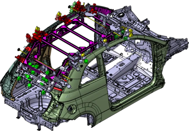
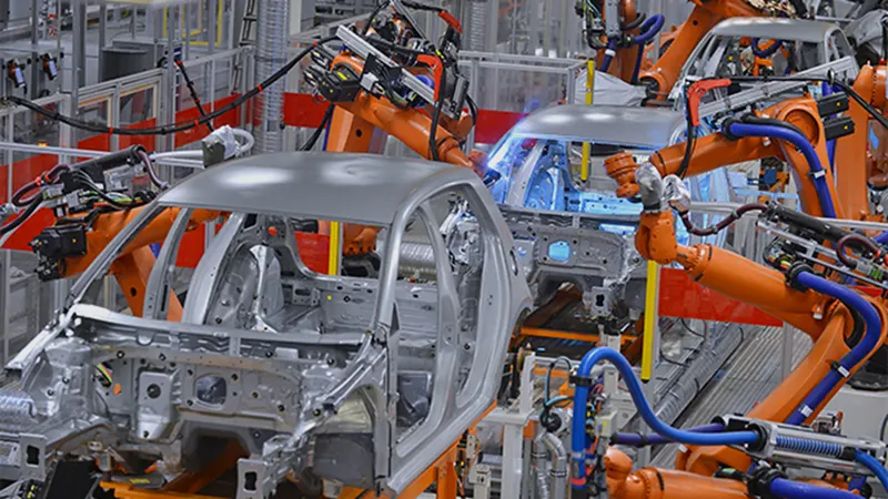
- As the name suggests, this fixture is used for mass production. It is a type of fixture on which car body gets assembled. It is a type of a fixture on which car body get assembled.
- These type of fixture require high consistency through it’s operation to maintain geometry of parts. So, material used for these types of fixture should be well tested as well as hardness level.
- The quality, in terms of dimension, tolerance should be met.
- These fixtures needs maintenance after certain period of time. So, the assembly and disassembly of the fixture should be easy as possible.
CHECKING FIXTURE:
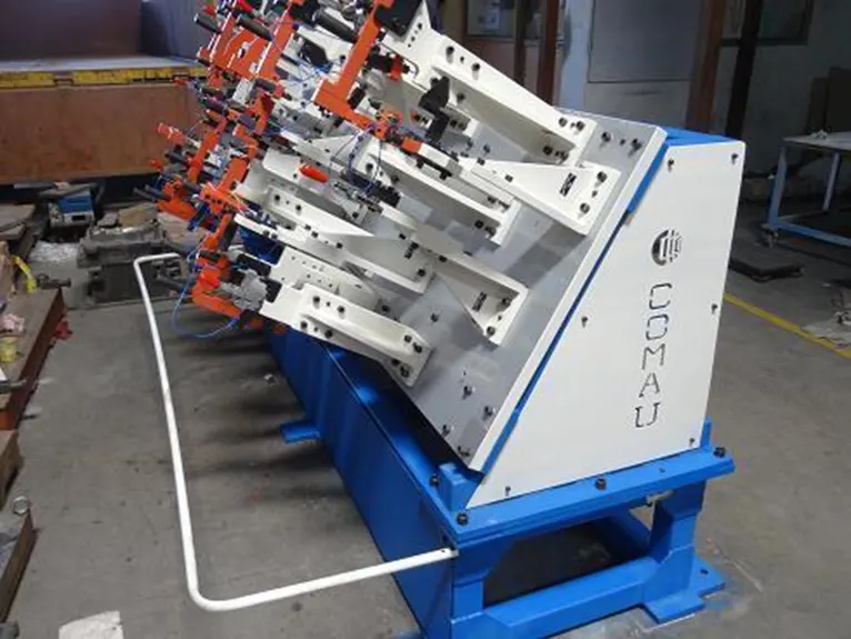
- As the name suggest, this fixture is used for checking assembly. Checking fixture are same as geo fixture except there are no option done like welding, gluing or hemming.
- Instead of that we use different in built gauges or external gauges to check various dimension, gap, relative dimension, tolerance. These data is compared with data provided by designer or design team.
- The geometry of welded parts also checked in this fixture to ensure the part maintains the required dimension and geometry.
4) What is the Basic Principles of Fixture Design?
PRINCIPLE OF FIXTURE DESIGN
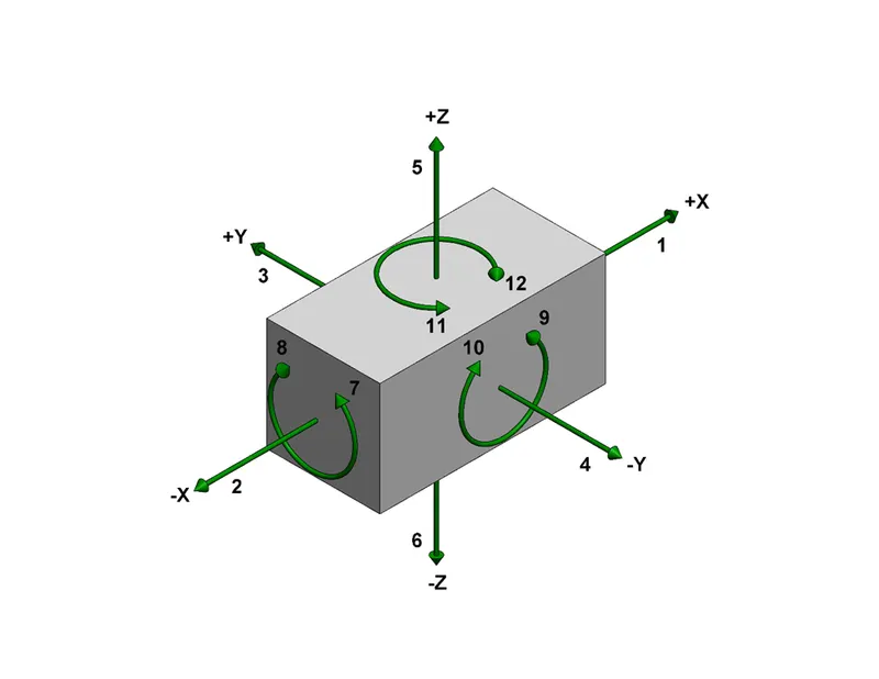
- The major portion of design time is spend deciding how to locate the workpiece in the fixture. We know that any free body has a total of 12 degrees of freedom.
3-2-1 Principle of Fixture Design
For a fixture designer, the major portion of design time is spent deciding how to locate the work piece in the fixture.
You know that any free body has a total of twelve degrees of freedom as below:
6 translational degrees of freedom**: +X, -X, +Y, -Y, +Z, -Z**
And 6 rotational degrees of freedom:
- Clockwise around X axis (CROT-X)
- Anticlockwise around X axis (ACROT-X)
- Clockwise around Y axis (CROT-Y)
- Anticlockwise around Y axis (ACROT-Y)
- Clockwise around Z axis (CROT-Z)
- Anticlockwise around Z axis (ACROT-Z)
You must fix all the 12 degrees of freedom except the three transitional degrees of freedom (-X, -Y and -Z) in order to locate the work piece in the fixture. So, 9 degrees of freedom of the work piece need to be fixed.
Rest the work piece on three non-collinear points of the bottom surface (XY), and you will be able to fix the +Z, CROT-X, ACROT-X, CROT-Y and ACROT-Y degrees of freedom
Now, rest the work piece at two points of side surface (XZ), and you will be able to fix the +Y and ACROT-Z degrees of freedom.
Now, rest the work piece at one point of the adjacent surface (YZ), and you will be able to fix the +X and CROT-Z degrees of freedom. So, you can successfully fixate 9 required degrees of freedom by using the 3-2-1 principle of fixture design.
PRIMARY LOCATOR:
- First, the three locators or supports are placed under the workpiece.
- It will be positioned on the primary locating surface also know as a datum.
- It will restrict 5 degrees of freedom.
SECONDARY LOCATOR
- The next two locators are normally placed on the secondary surface, restricting an additional 3 degrees of freedom.
TERTIARY LOCATOR
- This locator is positioned at the end of the part. It restricts 1 degree of freedom.
- All these 6 locators will restrict a total of 9 degrees of freedom. The remaining 3 degrees of freedom (1,4 & 5) will be restricted by the clamps.
- To minimize the time consumption in assembly and disassembly. Have to use minimum numbers of pins to arrest a maximum number of degrees of freedom.
- The jig and fixture are tools used for holding the workpiece in a correct location for mass production.
- Various types of fixtures (like drilling fixtures, milling fixtures and welding fixtures) are used in industry.
- The 3-2-1 method is the fundamental principle for all types of fixture design.
5) Elaborate type of BIW stations.
BIW STATIONS
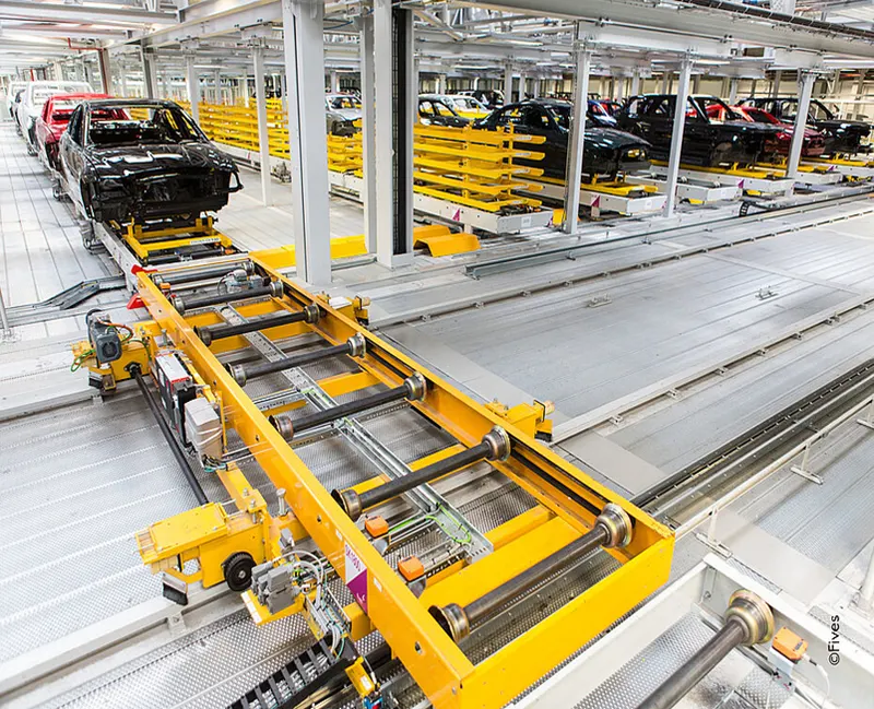
- BIW station is the part of the BIW assembly line. The BIW assembly line is divided into zones and these zones are divided into stations.
- The BIW stations are further divided into following such as
- Tool stations
- Gripper stations
- Stand stations
- Miscellaneous stations
1) TOOL STATIONS
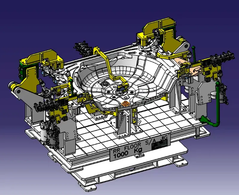
- In this station geometry of two parts are fixed. it can be either using welding or riveting . In this station precision and geometry of the finished product is defined Locating pins have closer tolerence of 0/-0.15.
- For example, the hole diameter of panel is 16mm then the pin diameter minimum can be 15.85.
- Diameter of locating pins should be lesser than the panel hole diameter. So Tolerence in locating pin is given in negative value.
- In Geo fixture spots or MIG welding done in such sequence that after taking out from the fixture it achieve the desired accuracy and doesn’t get disturb during transportation from Geo fixture to re-spot fixture.
- Geo fixture control the sub assembly accuracy in all the 3 axis.
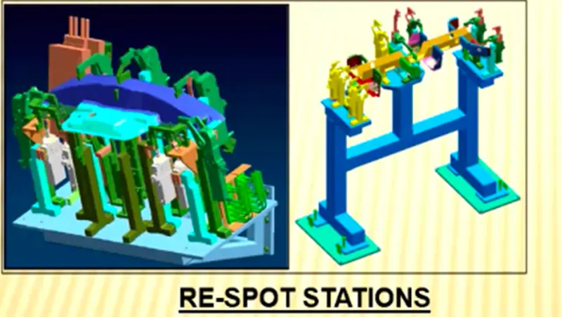
2) Re- Spot fixtures
- A re-spot fixture/tool is a fixture in which the remaining weld spots which are not achieved in geo tool are welded for the pre welded panel from the geo tool.
- Once product comes out of the Geo Station and there are left out spots where spot welding or riveting is to be done. then it is moved to another station , that station is called Re-spot station.
- These left out spots may be the due to clamp plan, cycle time,robot reach ability or any other various reasons.
- In this station pins with tolerence upto 0/-0.28mm.
- For example: Consider panel hole size 20mm, the pin diameter should be 19.72mm.
3) Marriage/Hemming fixture
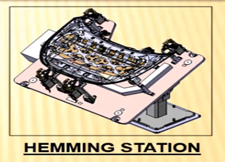
- In this Station inner and outer panels are joined. In this station to avoid the impression on the outer panel (A class surface), copper strips are used in between the weld tip and A-class surface.
- In case of closure panels, these are done by welding or hemming.
GRIPPER STATION
- A gripper is a device that enables the holding of an object to be manipulated. The easier way to describe a gripper is to think of the human hand.
- Just like a hand, a gripper enables the holding, tightening, handling and releasing of an object.
- A gripper is just one component of an automated system.
- A gripper can be attached to a robot or it can be part of a fixed automation system. Also known as End of Arm Tooling (EOAT).
Different grippers are used in BIW as follows.
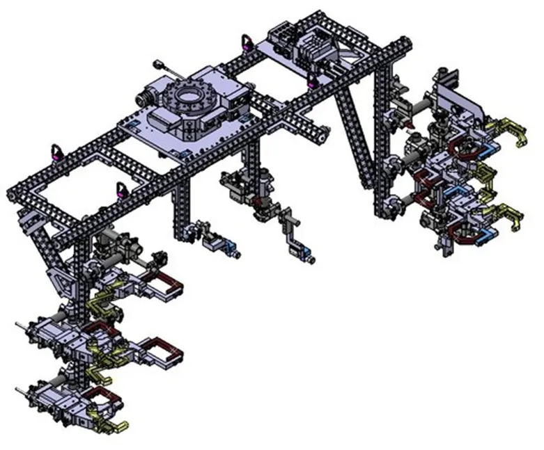
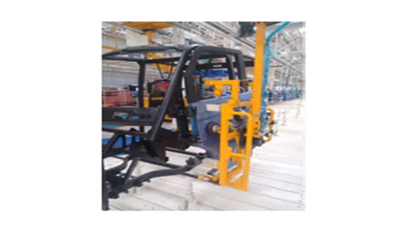
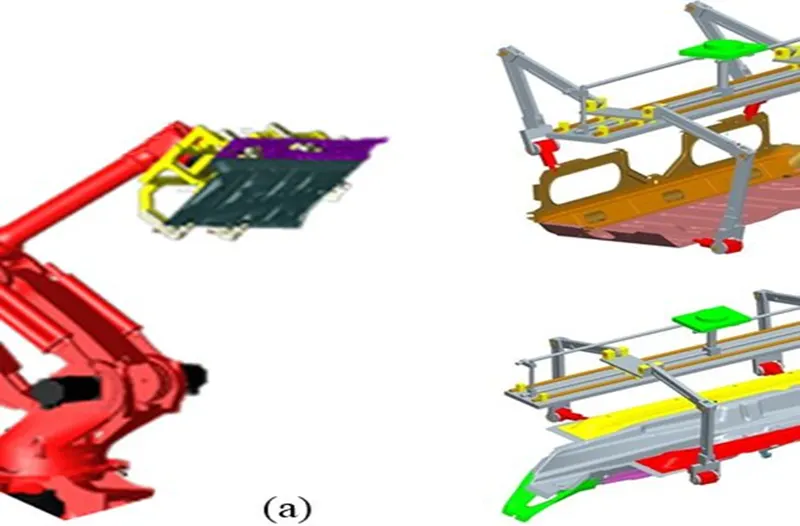
MATERIAL HANDLING GRIPPER
- Material handling gripper are designed for handling the car panel from one tool (station) to other tool (station).
PROCESS GRIPPER
- Process gripper are designed for handling the car panel from one station to other station.
- In addition to that, these grippers are also used to carry out some specific processes like gluing, pedestal welding, pedestal riveting, sealing, etc.
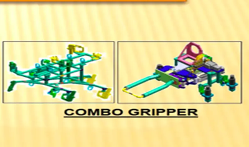
COMBO GRIPPER
- Combo grippers are the one which can carry out multiple tasks like it can do material handling and also with combination of weld gun at another side of the gripper for welding.
- Gripper-Weld gun.
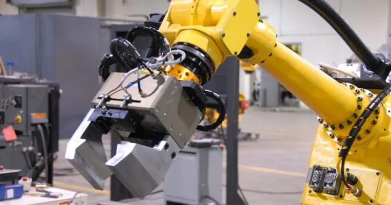
DUAL GRIPPER
- Dual grippers can also handle material and these are two-sided, in case when we want one LH and RH part, these grippers are used. It can handle the material from one station to another station.
- Gripper + Gripper
STAND STATIONS
- Stands are used to hold the part when not in use or also it is used to mount some parts or bodies on it.
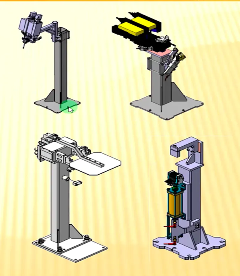
1) PEDESTAL STANDS
- Weld gun is mounted on the fixed stand which is mounted to the floor permanently, where the process gripper carries the car panel to weld the spot with the fixed weld gun.
2)GLUING AND SEALER STAND
- Gluing gun or sealer gun is fixed to a welded or a standard stand which is mounted on the floor.
3) DOCKING STAND
- The robots have some limitations such as the payload capacity of the robot.
- When we select the robot for multitasking it can’t do both the task simultaneously.
- In this kind of case, we add a docking stand to put some equipment that is not in use fir the current operation but will be required for next operation.
- So, the robot can drop a gripper or gun and pick the next operation equipment to complete the task from the docking.
4) DATE STAMP STAND
- Every manufactured product has some data to stamped or to be embossed on it like serial no, batch no, Date for some future reference or for data collection.
- The required data is stamped or embossed by using the stamping device mounted on it.
MISCELLANEOUS STAND
1) CURING
- After gluing it needs some time to cool down, so we put the assembly on some belts & it will take the panel to another station and meanwhile gluing will cool down,
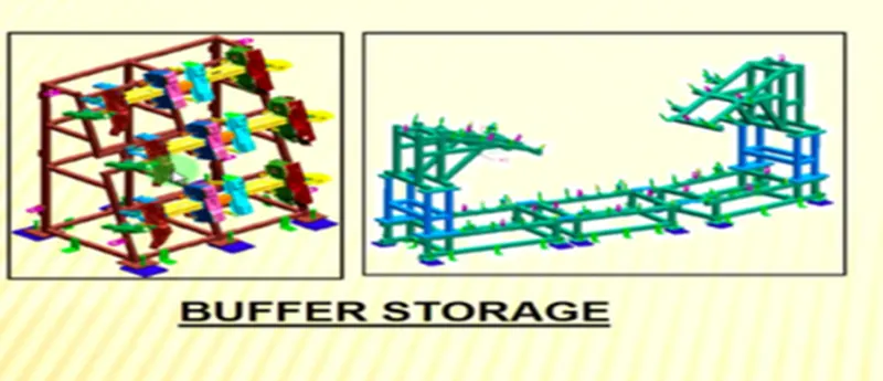
2) BUFFER STAND
- After some operation, we can put the no. of assemblies in this stand which is buffer stock and it can be transported to another station easily.
- They are also used to store the inventory while the machine is undergoing some maintenance.
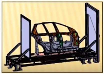
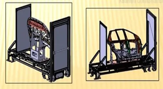
3) TAKE OUT TROLLEYS
- The conveyor is the rotating moving path that transports the parts to the next station which are kept over it.
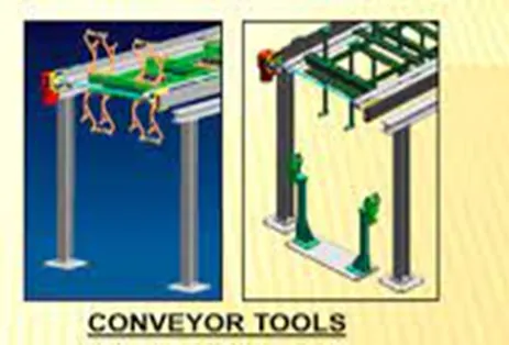
4) CONVEYOR
- The conveyor is the rotating moving path that transports the parts to the next station which are kept over it.
6) What are the basic terminologies used in the BIW Fixture?
The terminologies used in the BIW fixture are as follows
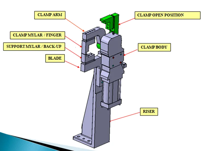
1) NC/MYLARS/FINGERS/
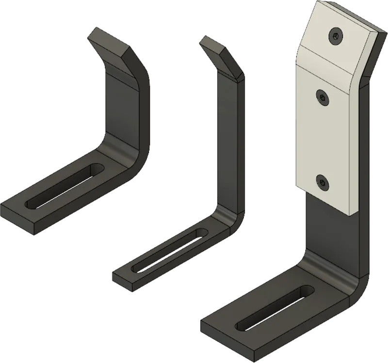
- Mylars are the component that holds the panel while these are placed from topside and from the bottom side also.
- The topside Mylars called Clamping Mylars and the bottom side Mylars called Resting Mylars.
- Every clamping Mylars have resting mylars. It doesn’t allow deformation of the part due to welding stresses.
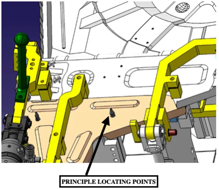
2) PRINCIPLE LOCATING POINT (PLP)
- These are used to accurately locate the workpiece on the fixture to process the workpiece.
3) Blade
- Blades are the plated which are attached to the risers.
4) Risers
- Risers are different types like L-typer rises, welded, Square tube riser.
- Riser is the manufacturing part which gives height to the assemblies.
- SHIMS
- Shims are the small part that comes with the thickness of 0.1mm, 0.2mm, 0.5mm, etc.
- These will compensate for the stackup tolerane which reflects at the panel holding part.
- We give tolerance to all the parts of the fixture. Due to this tolerance, the mylars will either lift up or goes down from their defined position.
- If the Mylars go down from the defined height it will make an impression or dent on the panel.
- If the Mylars lift up then there will be a distortion due to welding stress. To adjust the Mylars at its defined position we use shims so the panel won’t be deformed and also don’t get any impression on it.
- ROUGH LOCATORS
- The operator can place the part in the wrong orientation. The rough locator will work as a guide while placing the part in the fixture and the part will be loaded in the exact orientation.
- HARDWARE
- Hardware are the Hex head bolts, Allen bolts, Hex nuts, Spring washers, Self-locking nuts.
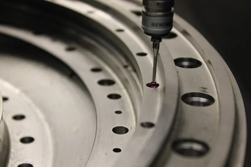
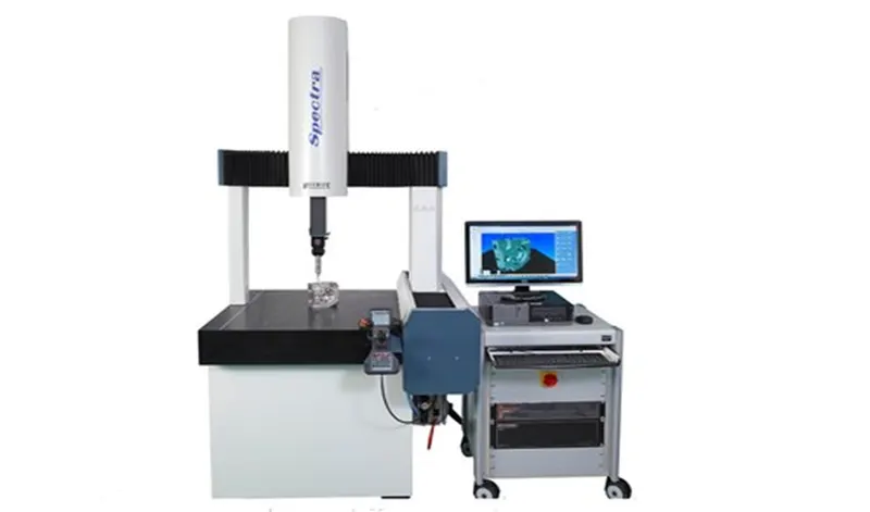
- CMM (Coordinate Measuring Machine)
- CMM stands for coordinate measuring machine. It is a device that measures the geometry of physical objects by sensing discrete points on the surface of the object with a probe.
- It generates a report by comparing the data with the CAD file data.
5) UNITS
- The fixture is the assembly of different types of units.
- There are different units like pin unit, base unit, clamping unit, etc. which makes a complete assembly.
6) NUMBER PLATES
- The number plate is the aluminium embossed plate placed on each unit for easily recognizing the unit.
- CO-ORDINATE PLATES
- Every fixture has a tooling hole through which all fixture checked. Co- ordinate plates are used to cover the hole.
7) NAMEPLATE
- The data like manufacturing company name, fixture type.
- Fixture weight is embossed on the plate and joined to the fixture.
8) CLAMP ARM
- The clamp arm is the part of the clamp unit which moves with the Mylars mounted on it to hold the assembly.
9) PIVOT
- It is an axis about which the clamp arm will rotate or move.
10) CLASS A SURFACE/ SKIN SURFACE
- The outer panels of the car like a hood, door, backdoor, fender, roof are visible to the customer.
- Those outer panels should be aesthetically very good. No scratches or dent is acceptable over it.
- While designing the fixture for the skin surface the clamping material should be soft, so that it could not be able to left any impression or dent over the skin,
- Generally, Nylon or PU material is used for clamping purposes.
11) REED SWITCHES AND SENSORS
- These are the electric components, the reed switch and sensors are only used in automated fixture.
- They detects that panel is loaded or not on the fixture assembly.