Week 1:- Introduction to BiW and Fixtures Challenge
1. What is BIW & define its parts?
- BiW stands for Body in White
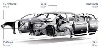
- A body in white is an assembly of a frame and panels, made up of homogeneous materials (for instance, steel or aluminum sheets or composites).
-Body in white or Biw refers to the stage in automobile manufacturing in which the car body sheetmetal (including doors, hoods, trunks, bumpers and deck lids) has been assembled but before the components (engine, chassis, exterior and interior trim i.e. door coverings, roof liners, carpets, seats, electronics, plastic trim parts) have been added.
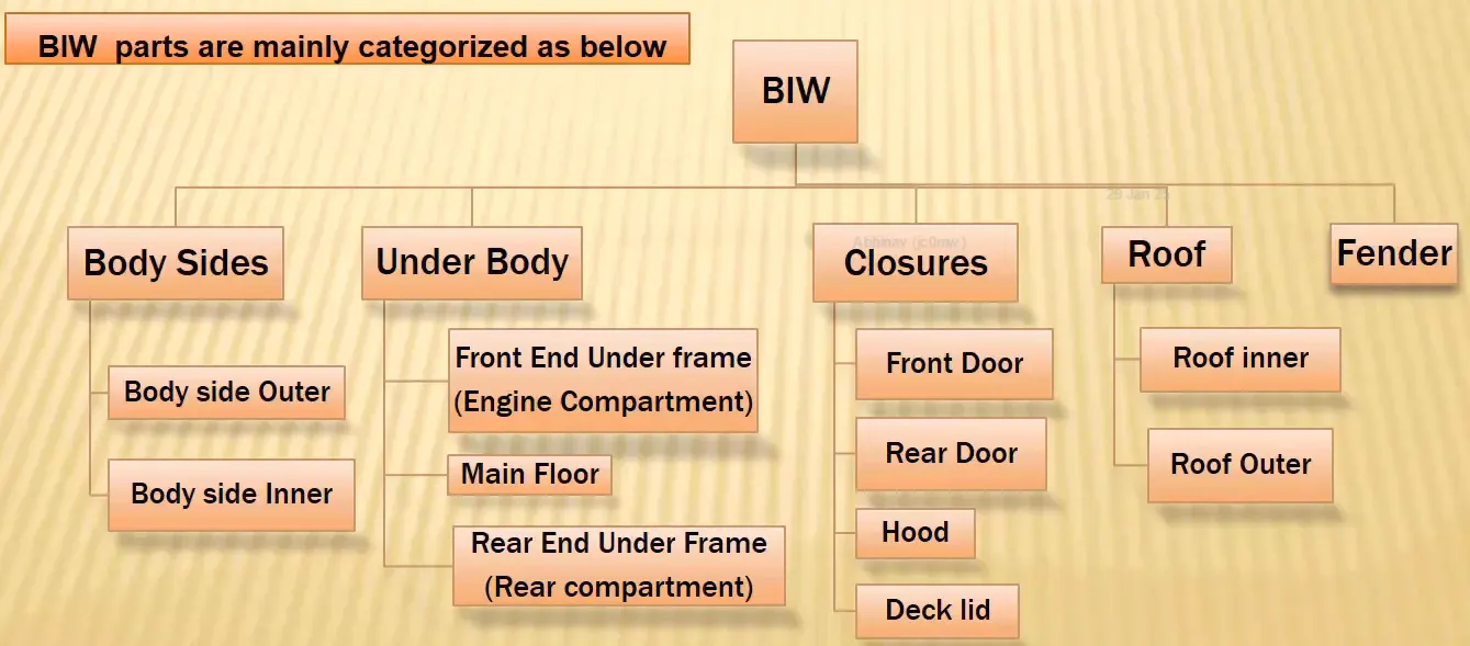
Biw parts are mainly categorized as below
- Body Sides :
a) Body side outer
b) Body side inner
-Underbody :
a) Front end under frame (Engine Compartment)
b) Main floor
c) Rear End Under Frame (Rear Compartment)
- Closures :
a) Front Door
b) Rear Door
c) Hood
d) Deck Lid
- Roof :
a) Roof inner
b) Roof outer
-Fender 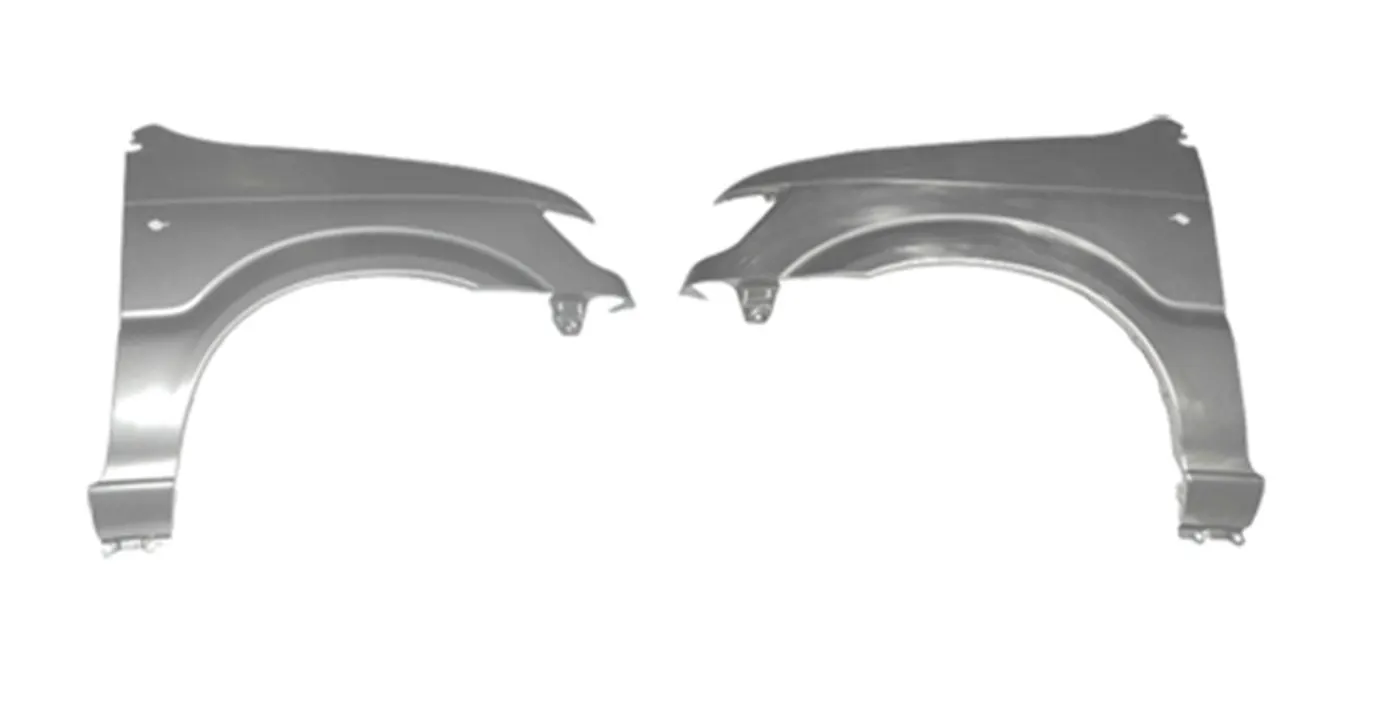
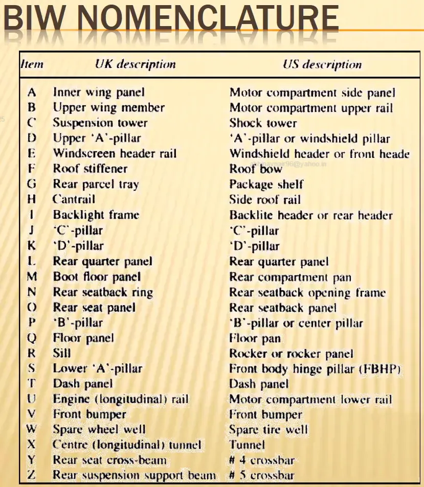
2. What do you understand by BiW nomenclature?
Body in white (BIW) is the stage in automobile manufacturing in which a car body's frame has been joined together, that is before painting and before the motor, chassis sub-assemblies, or trim (glass, door locks/handles, seats, upholstery, electronics, etc.) have been integrated into the structure. Assembly involves different techniques such as welding (spot, MIG/MAG, or friction stir), riveting, clinching, bonding and laser brazing.
The term derives from manufacturing practices before steel unibody monocoques, when automobile bodies were made by outside firms on a separate chassis with an engine, suspension, and bumpers attached. The manufacturers built or purchased wooden bodies (with thin, non-structural metal sheets on the outside) to bolt onto the frame. The bodies were painted white prior to the final color.
A folk etymology for "body in white" is the appearance of a car body after it is dipped into a white bath of primer (undercoat paint)— despite the primer's actual gray color. BIW could also refer to when car bodywork would be made of timber – all timber products, furniture, etc., are considered to be "in the white" when at the stage of raw timber before finishing or varnishing.
In car design, the "body in white" phase is where the final contours of the car body are worked out, in preparation for the ordering of the expensive production stamping die. Extensive computer simulations of crash-worthiness, manufacturability, and automotive aerodynamics are required before a clay model from the design studio can be converted into a body in white ready for production.
Factories may offer BIW cars to racers, who then may replace up to 90% of the car with aftermarket parts, and niche manufacturers like Ruf Automobile start their cars with BIWs from other makers.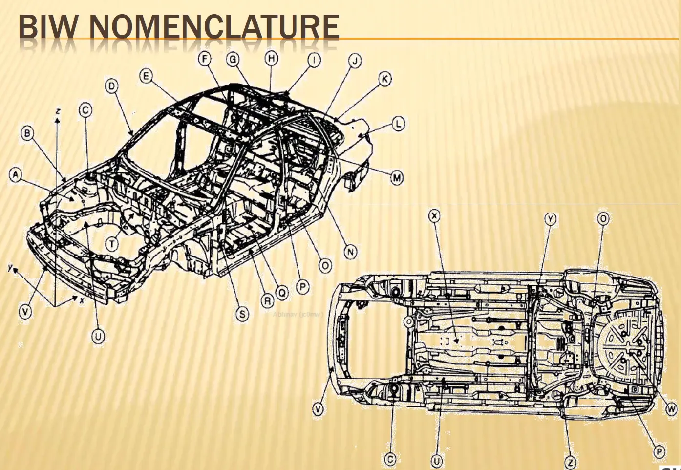
3. What is fixture & its types ?
Fixtures - A fixture is a device which holds the work piece to be processed (welded), by using 3-2-1 principle.
In general a welding fixture (tool) consist of number of units together to hold the car panel, and is mounted on a base unit.
Welding fixtures are normally designed to hold and support the various components (work pieces) to be welded. It is necessary to support them in a proper location which is capable of preventing distortions in work pieces during welding. For this the locating elements need to be placed carefully, clamping has to be light but firm, placement of clamping elements has to be clear of the welding area and the fixture has to be quite stable and rigid to withstand the welding stresses.
Types of fixtures:
Below are the general types of BiW fixtures
Pre production operation fixtures (PPO)
These fixtures are commonly used during the prototype stage to test the productivity and feasibility of the fixture. They require a lot of study and detailing because they are used in the pre-production stage. If a new standard or process is required, the pre-production fixture is modified to become the production fixture used on the assembly line.
Production fixtures :
Once the Pre-Production Fixture is tested and approved, it is modified to become the Production Fixture. This fixture is used on the assembly line to manufacture automobiles. The Production fixture is more robust and efficient, and it requires less maintenance compared to the Pre-Production Fixture. 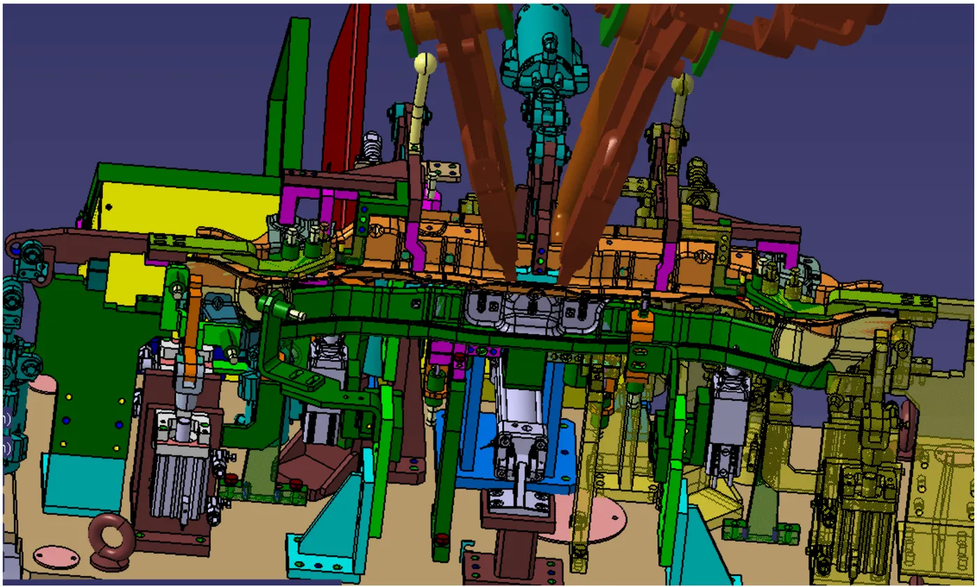
Checking fixtures
During the inspection of BIW sheet metal, various types of fixtures are used to examine the produced sheet metal. These fixtures are used to verify if the sheet metal meets the required tolerances, geometries, dimensions, and other specifications. The gauges, which are used for fixing the parts, are a crucial component of the inspection process. They help ensure that the inspection process is conducted with utmost accuracy and precision. By leveraging these tools, technicians can identify any faults or inconsistencies in the sheet metal, and take corrective measures to ensure that it meets the required specifications. 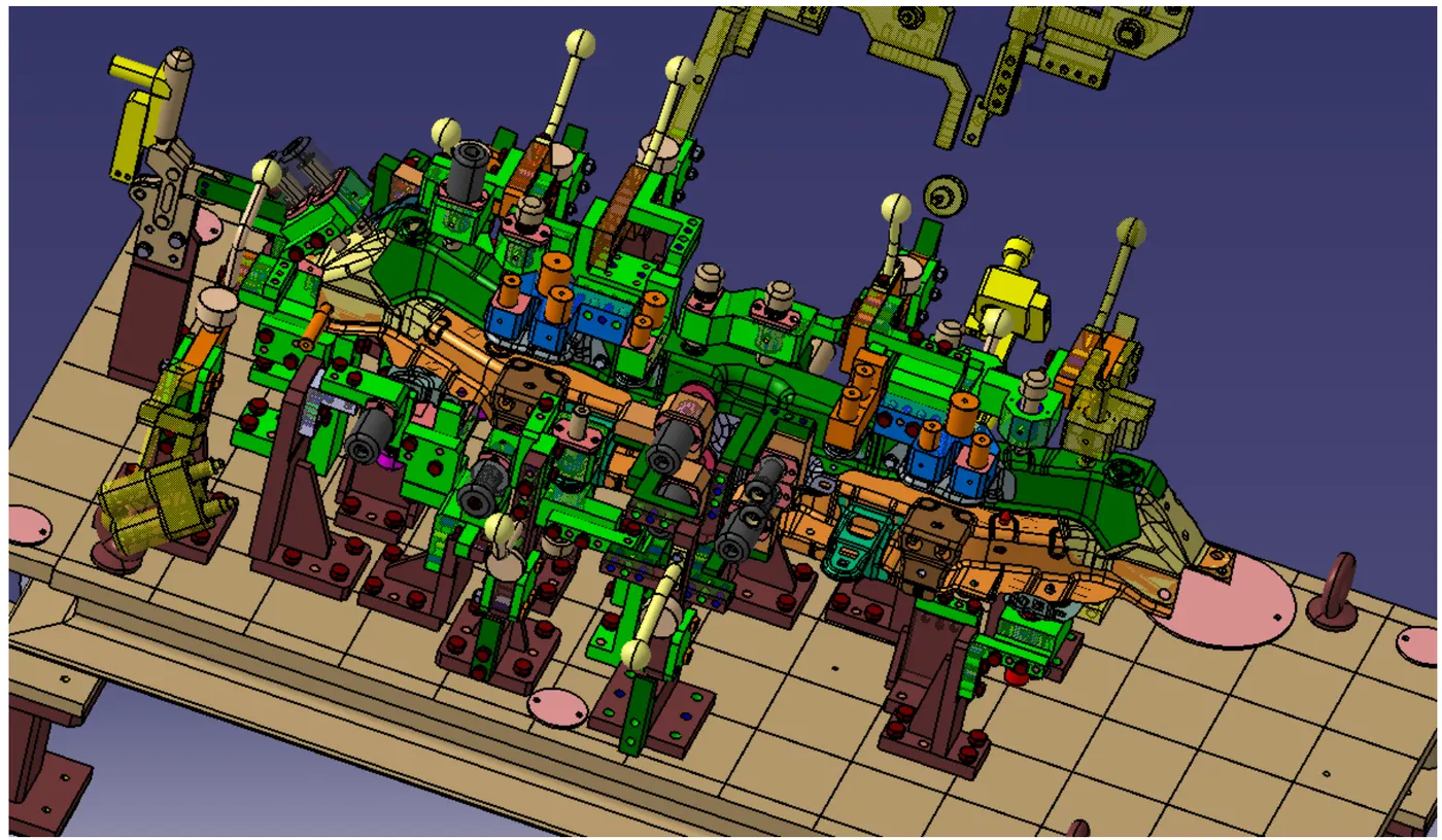
4.What is the basic principle of fixture design ?
Principle of fixture Design:
For a fixture designer, the major portion of design time is spent deciding how to locate the work piece in the fixture.
For any free body there are total of twelve degrees of freedom as below:
6 translational degrees of freedom : +x, -x, +y, -y, +z, -z
And 6 rotational degrees of freedom:
Clockwise around X axis
Anticlockwise around X axis
Clockwise around Y axis
Anticlockwise around Y axis
Clockwise around Z axis
Anticlockwise around Z axis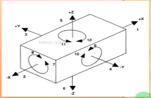
You must fix all the 12 degrees of freedom in order to locate the work piece in the fixture. So, 12 degrees of freedom of the work piece need to be fixed & thus we can achieve zero degree of freedom for the work piece.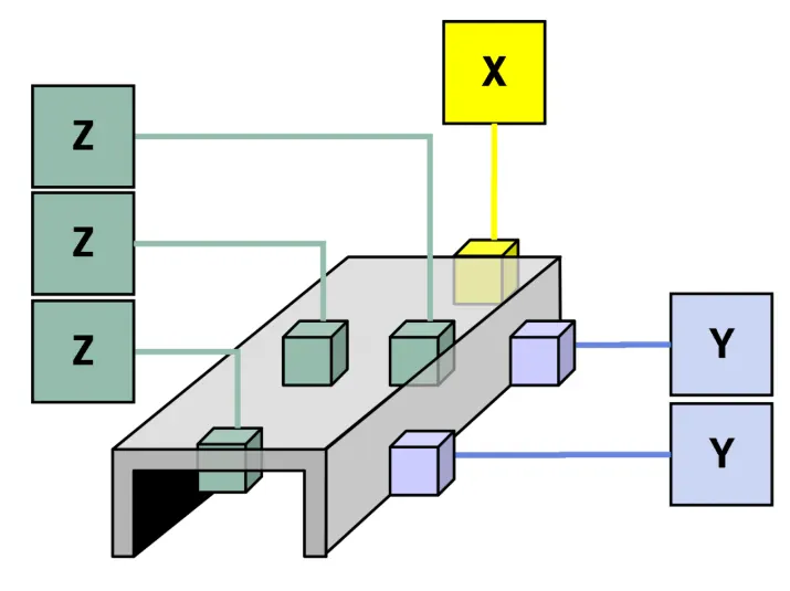
5.Elaborate types of BiW stations ?
Assembly Line :
An assembly line is a process in which car panel/ car body parts are joined as the semi finished assembly moves from one station to another station until the final product is produced.
In the process of joining in assembly line, panels are moved from panels are moved from one section to another sections. Those sections are called station.
In Biw fixture designing we have various stations which are used to locate the panels so that joining processes can be done.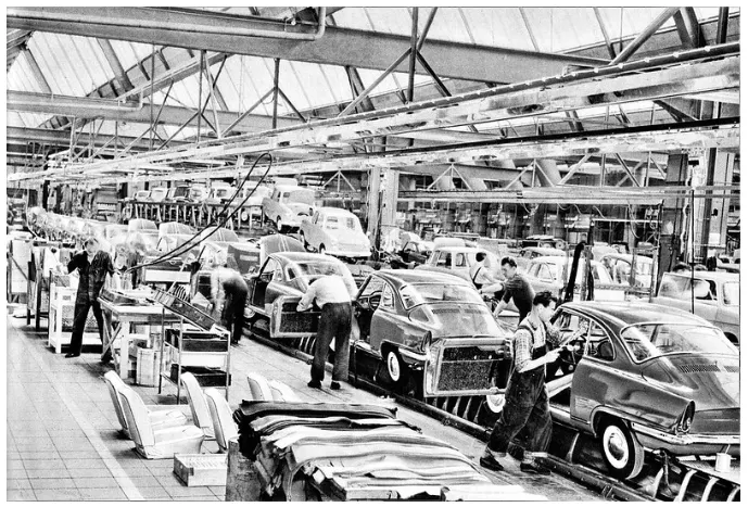
Some of these stations are:
a) Geo station :
In this station geometry of two parts are fixed. It can be either using welding or riveting. In this station precision and geometry of the finished is defined. Locating pins have closer tolerance of 0/0.15 mm.
Suppose the hole diameter of panel is 16mm then the pin diameter minimum can be 15.85mm.
Diameter of locating pins should be lesser than the panel hole dia. So tolerance in locating pin is given in negative value.
b) Repost Station:
Once product comes out of the geo station and there are left out spots welding or riveting is to be done.
Then it is moved to another station, that station is called Re-spot station.
These left out spots may be the due to clamp plan, cycle time, robot reach ability or any other various reasons.
In this station pins tolerance upto 0/0.28 is maintained.
c) Pedestal Station:
In this station, pedestal gun is mounted on a tool and panel is manipulated manually or by robot to weld the panels.
Pedestal station is generally a Re spot station.
Re spot station and pedestal station, both perform same kind of operation. But to decide whether to go for pedestal or a re-spot station some parameters needs to consider like cycle time, floor space, no. welds, clamp plan, or size of the panel.
d)Loading station:
This station is used for loading of panel and some station is used to change the orientation of the if it is required in the upcoming station.
Sometime this station is used when robots are unable to transfer panel from one station to another.
e)Buffer Station:
This station is used to make the balance between the process.
Some stations carry out process in lesser time as compared to their respective stations. In that case panels can be stored in one station so that assembly line process remains smooth.
f) Sealer Station:
In this station sealant application is carried out.
This process can be carried out manually or by using robots. Sealer is used in between two panels so that panels do not flatter due to friction.
g) Marriage Station:
In this station inner and outer panels are joined. In this station to avoid the impression on the outer panel (A class surface), copper strips are used in between the weld tip and A-class surface.
h) Curing Station:
In this station product received after sealing application, is kept idle at ambient temperature, which allows sealant to get dry with better bonding between the panel.
6.What are the basic terminologies used in the BiW fixture?
BIW FIXTURE BASIC PARTS TERMINOLOGY
Some basic manufacturing parts commonly used in Body in White (BIW) fixture design are Mylar, Pin, Blade, L Block, Pin Block, Riser, Weldment, etc.
Shimming:
Using thin plates of varying thickness to adjust gaps or ensure a better fit. The thickness of shims can range from 0.25mm to 2mm, and shimming itself can be of different thicknesses, such as 5mm, 8mm, or 10mm. The purpose of shimming is to address manufacturing errors and achieve the desired fit between Mylar and panel by adjusting gaps in the X,Y, or Z directions.
There are three types of shimming: one-way, two-way and three way. The choice of shimming depends on the NC cut angle and PIN angle with the car line. If the NC cut is less than 15 degrees in one direction, one-way shimming is used. For NC cuts greater than 15 degrees in one direction, two-way shimming is applied. If the NC cut has angles exceeding 15 degrees in two directions, three-way directional shimming is utilized.
The case for pins involves different criteria. If the pin's angle with respect to the car line is not more than 15 degrees, two-way directional shimming is employed. However, if the pin's angle exceeds 15 degrees in any direction, three-way shimming is used for adjustment.
MYLAR:
Mylars are blocks that come in contact with the panel and serve to hold or clamp it in place. They are designed in car line. Generally, mylars are made of steel.
Mylars are also referred to as NC (Numerically controlled) blocks, suggesting a connection to computerized or automated manufacturing processes.
Mylars are mounted on blocks or plates using shimming, allowing for the adjustment of the mylar height during assembly. This adjustability is likely crucial for achieving precision in the manufacturing process.
For 'A class surfaces, nylon mylars are specified. This choice is likely made to prevent scratches and maintain the quality of the surface finish.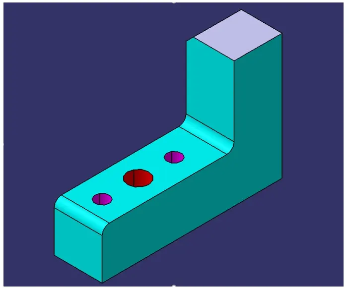
PIN:
Pins are used to lock the rotational movement of a panel, with different types of pins such as Round pin and diamond pin. The use of two and three- directional shimming depends on the angle of the pin with respect to the carline. Additionally, collared pins are used when the pin is meant to support the panel, and in such cases, 3-way shimming is provided regardless of the pin's angle to the carline.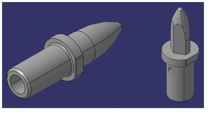
BLADE:
The plate connecting the Riser to the clamp cylinder is referred to as the "Blade", and its design is crucial for the unit's construction, keeping it compact is a key considerations. Compact design is often important for efficiency, space utilization, and overall functionality.
When designing the blade, you may want to consider factors such as material strength, weight, and the specific functions it need to perform within the unit. Additionally, the choice of material, manufacturing process, and any required structural features should align with the overall goals and specifications of the unit.
If the plate can be of any shape, it allows for flexibility in design. Depending on the requirements, you might explore geometric shapes that optimize strength and reduce material usage, contributing to the desired compactness.
It's essential to collaborate with engineers and designers, conduct simulations or prototypes, and iterate through the design process to ensure that the blade meets all necessary criteria. The goal is to create a plate that not only connects the riser to the clamp cylinder effectively, but also enhances the overall performance and reliability of the unit. 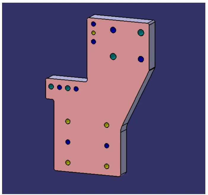
PIN BLOCK:
In manufacturing, pin holders play a crucial role in fixtures, which are devices or systems used to securely hold and position workpieces during machining, assembly, or inspection processes. Pin holders are specifically designed to accommodate and secure pins that aid in the alignment and fixation of the workpiece. Here are some key points about the use of pin holders in manufacturing fixtures:
a) Alignment and Positioning
b) Fixture Design
c) Variety of Pins
d) Material compatibility
e) Interchangeability
f) Fixturing systems
g) Automation
h) Customization
Overall, pin holders contribute to the overall effectiveness and precision of manufacturing fixtures, helping to maintain consistency, reduce errors, and improve the efficiency of production processes.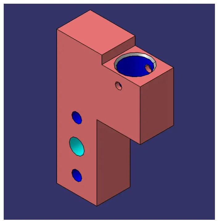
RISER:
A riser, is a component mounted on a baseplate that holds a clamp or pin cylinder. It can be either a standard part or a manufactured part, and it may come in different shapes and sizes depending on the project requirements. Additionally,a riser can be a single part or a welded part.
In engineering and manufacturing, risers are often used to elevate certain components or structures to a desired height. The choice between a standard or manufactured riser, as well as the decision to use a single part or a welded assembly, would depend on the specific needs and specifications of the project.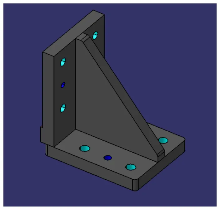
WELDMENT:
A weldment refers to the assembly of two or more parts that are joined together through welding. The process involves the application of heat and pressure to melt and fuse the materials, creating a strong bond. The mention of a “5 mm overlay” suggests that, as a general guideline, it is common to have a 5 mm overlap between the edges of the plates being joined. This extra material provides space for the welding operation and ensures a secure and robust weld joint.
The specific dimensions for overlay and welding considerations can vary depending on factors such as the type of welding process, material thickness, and the welding specifications for a given project. It’s essential to follow industry standards, welding codes, and design requirements to ensure the integrity and quality of the weldment.
Additionally, weldments can indeed vary in size and complexity, involving any number of plates depending on the design and structural requirements of the final assembly. The choice of welding method, such as arc welding, MIG (Metal Inert Gas) welding, or TIG (Tungsten Inert Gas) welding, may also depend on the specific characteristics of the materials being joined and the overall application of the weldment.