Week 1:- Introduction to BiW and Fixtures Challenge
1.What is BIW & define its parts?
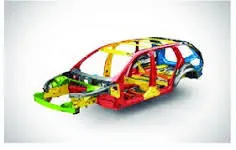
Body in white (BIW) is the stage in automobile manufacturing in which a car body's frame has been joined together, that is before painting and before the motor, chassis sub-assemblies, or trim (glass, door locks/handles, seats, upholstery, electronics, etc.) have been integrated into the structure. Assembly involves different techniques such as welding (spot, MIG/MAG, or friction stir), riveting, clinching, bonding and laser brazing. The term derives from manufacturing practices before steel unibody monocoques, when automobile bodies were made by outside firms on a separate chassis with an engine, suspension, and bumpers attached.The manufacturers built or purchased wooden bodies (with thin, non-structural metal sheets on the outside) to bolt onto the frame. The bodies were painted white prior to the final color.A folk etymology for "body in white" is the appearance of a car body after it is dipped into a white bath of primer (undercoat paint)— despite the primer's actual gray color.BIW could also refer to when car bodywork would be made of timber – all timber products, furniture, etc., are considered to be "in the white" when at the stage of raw timber before finishing or varnishing.In car design, the "body in white" phase is where the final contours of the car body are worked out, in preparation for the ordering of the expensive production stamping die. Extensive computer simulations of crash-worthiness, manufacturability, and automotive aerodynamics are required before a clay model from the design studio can be converted into a body in white ready for production. Factories may offer BIW cars to racers, who then may replace up to 90% of the car with aftermarket parts, and niche manufacturers like Ruf Automobile start their cars with BIWs from other makers.
Underbody structure

Underbody refers to the belly of your car, the underside that sits closest to the road. Everyday as you drive, rocks, road debris, and salt on snowy roads brushes up against the underbody of your car.
Front end structure
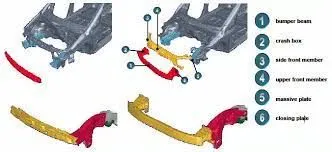
Auto-body’s front end structure, such as bumper and crash box, has the vital function of protecting other components from damage during low-velocity collision; moreover, it should accomplish excellent lightweight effect under the insurance of crashworthiness.
Body side structure
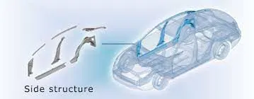
Vehicle body could be the main supporting structure or its particular element. The Vehicle Body of modern car consist of: engine section, saloon, trunk. Vehicle body is the main supporting structure of a vehicle, to which all other components are attached. Truck uses a separate frame as chassis.
Closure
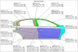
Automotive parts such as bonnets, back doors, side doors, sunroofs, sliding doors, window and fuel doors are all referred to as automotive closures.
Roof
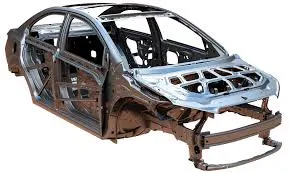
An automobile roof or car top is the portion of an automobile that sits above the passenger compartment, protecting the vehicle occupants from sun, wind, rain, and other external elements. Because the earliest automobiles were designed in an era of horse-drawn carriages, early automobile roofs used similar materials and designs.
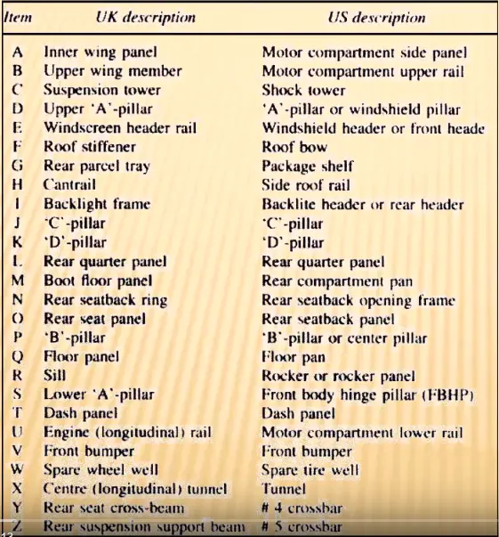
2.What do you understand by BIW nomenclature?
Automotive BIW (Body in White) has a prime importance in reflecting the character and performance of the vehicle body. Design of vehicle body-in- white structures, significant attention is given to the characteristics of the fundamental frequencies. Lower order modes have a pronounced effect on ride and handling and good NVH characteristics. Similarly the strength, stiffness, Crashworthiness and safety design plays major roles for the BIW /Vehicle body design. Hypersonic Tech solution has meticulously designed curriculum for design Engineer to start the career in automotive field.
- Automotive body Basics. Branding, Vehicle Specification, Major functions, Ergonomics etc.
- Evolution, Different types of constructions, Benchmarking etc. Classification, types, sub-assembly and assembly.
- Automotive BIW design Development. Vehicle design program Specification and vehicle Integration.
- Design Process for complex depression, flange, beads, & bow Packaging data, Costing, Fit and Finish.
- Vehicle Body Engineering / commercial vehicle.
- IBOM, Subsystems & Part.
- DFM, DFA, DFMEA AND Quality Standards.
- CAD, GD&T. Model Preparation from IGES, surfacing, Missing surface & Drafting.
- Basic and advance modules, Mechanism design, synthesis, sheet metal, etc.
- Automotive BIW development & Manufacturing. Specification, Different types of constructions.
- BIW parts forming and Manufacturing process.
- BOM, Subsystems, Assembly, Part nomenclature.
- BIW system virtual validation Bending/ Tensional stiffness calculations of BIW.
- Dent Analysis, Roof stiffness analysis.
- FE modeling & assembly of complete car for crash and durability simulations.
3. What is fixture & its types?
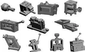
A fixture is the device which holds the work piece to be processed (welded) by using 3-2-1 principle. In BIW fixture, the fixtures are designed to hold no. of parts during welding. It is necessary to hold the parts at proper location to avoid the distortions & to maintain the required geometry of the parts.
Turning Fixtures
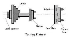
They are usually mounted on chucks of the machine spindle during turning operations, like on lathes. Depending on the part that’s being machined, turning fixtures may be equipped with counterweights to balance an unbalanced fixture.
Milling Fixtures
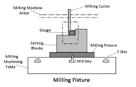
Milling fixtures are usually mounted on machining tables facing the faceplate or the spindle of the milling machine. The workpiece is placed at the base of the fixture and clamped before starting milling operations. However, during operation the cutting tool remains in place while the machining table, alongside the piece, shifts in relation to the cutter.
Boring Fixtures
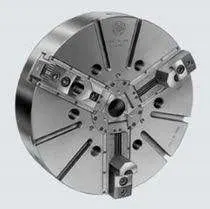
Boring fixtures incorporate the principles of drill jigs since the boring bar is guided through a pilot bushing, similar to drill bushing. Its main function is to hold the workpiece in the correct position relative to the boring bar. Since they aren’t subject to strong cutting forces, boring fixtures don’t need to be as sturdy.
Grinding Fixtures
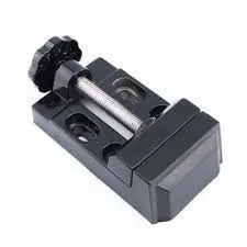
There are several different forms of grinding fixtures used in grinding machines to hold, locate, or support workpieces that are subject to grinding operations. Regardless of their form, however, these should have provisions for the supply and exit of coolant.
Tapping Fixtures
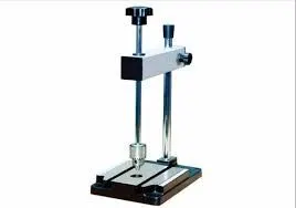
These work holding devices are specifically designed to position and secure workpieces for tapping operations — cutting internal threads in drill holes. They’re primarily used on odd-shaped and imbalanced parts, especially in mass production, for drilling, tapping, and reaming.
Indexing Fixtures
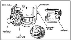
These are specifically used for machining parts that must have machined details evenly spaced.
Welding Fixtures
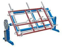
Welding fixtures are designed to hold and support different components intended for welding operations and to prevent any possible distortions in welded structures. The structure of these fixtures has to be rigid and stable, and the clamping elements need to be positioned clear of the welding area.
Duplex Fixtures
D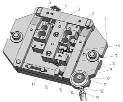 uplex fixtures are designed to facilitate simultaneous machining of two parts at separate machining stations. Depending on the manufacturing needs, these parts can be machined identically or in sequence.
Assembly Fixtures
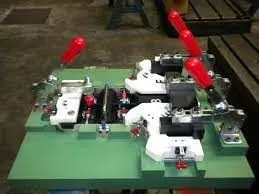
These are used to hold various parts and components together for assembly purposes. They’re similar to welding fixtures, but instead of hot joining, these are used for mechanical assembly.
Broaching Fixtures
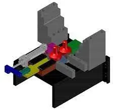
Mostly used with plate fixtures, broaching fixtures are used to hold the workpiece during broaching operations.
3. What is the basic principle of fixture design?
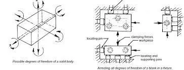
The art of metalworking has a primary concern, locating the part to be machined relative to the platform. A CNC machine starts machining at a specific point corresponding to the fixture and proceeds from there. Therefore, the preciseness with which a job is machined is dependent on the accuracy that holds in the fixture. The accurate location of every part loaded into the fixture is essential. Any deviation in part location adds to the dimensional tolerance that must be assigned to the finished pieces. Furthermore, improper supporting and securing the part in the fixture affects surface finishes by temporarily or permanently deforming it. Hence, techniques for supporting, clamping, and locating must be considered together to assure repeatability from part to part.
LOCATING POINTS: Locating the work is a prime necessity and requires suitable facilities. The correct setup ensures smooth insertion of a workpiece in the proper position and removing a workpiece from a jig without operational hassles or time consumption. The workpiece position needs to be precise with the guiding tool in the jig or setup pieces in the fixture.
FOOLPROOF: A foolproof design of jigs and fixtures does not permit a tool or workpiece to be placed in any other way other than the intended one.
REDUCTION OF IDLE TIME: Jigs and Fixtures must be designed in such a way that ensures smooth loading, clamping, machining, and unloading of a
WEIGHT OF JIGS AND FIXTURES: A jig and fixture must be compact, easy to handle, and low cost regarding the number of materials used without giving up stiffness and rigidity.
JIGS PROVIDED WITH FEET: Some jigs require feet so that they can be placed on the table firmly.
MATERIALS FOR JIGS AND FIXTURES: Jigs and Fixtures are usually created with hardened materials to resist wear & tear and avoid frequent damage—for example, Mild steel, Cast iron, Die steel, High-speed steel, Caesium.
CLAMPING DEVICE: A suitable clamp is rated for its strength. It should be able to hold a workpiece firmly in its position while bearing the strain of the cutting tool simultaneously, without springing.
5. Elaborate types of BIW Stations?
GEO TOOL FIXTURE
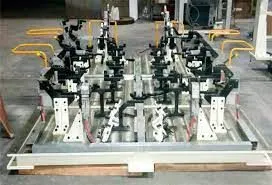
A Geo tool is a fixture in which the geometry of the panels which are welded together is defined accurately. The pin tolerance for a geo pin will be of closer tolerance i.e 0.15 in general. For example: consider panel hole size 20mm,then the pin dia should be 19.85mm. It is a veryprecise fixture.
RESPOT TOOL
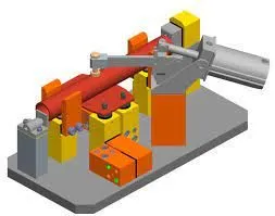
Respot tool is a fixture in which the remaining weld spots which are not achieved geo tool are welded for the pre welded panel from the geo tool. The weld spot which has been done in this tool is only for rigid or stifness prpose. where the geometry of the panels are already controlled in Geo Tool.
MARRIAGE TOOL
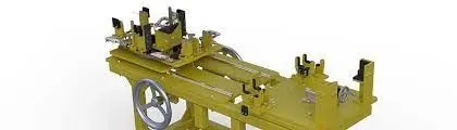
A Marriage Tool is a fixture in which the inner pannel assembly & outer pannel assembly are joined. Hemming in case of closure paanels.
FRAME TOOL
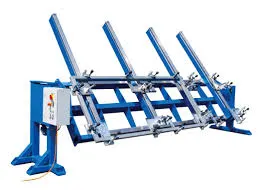
In framer fixture the roof is attached to the output of the marriage fixture & it form like frame hence it is called as framer tool. - These are used to check the assembly of parts, Tolerance ,Dimensions & coordinates.
CHECKING TOOL FIXTURE
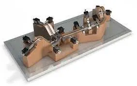
A checking fixture is a quality assurance tool used in industries to check for the quality of components with complex shapes. They aren't used in making components but to accept or reject already made components according to the dimensional accuracy.
6. What are the basic terminologies used in the BIW fixture?
In this section, we will learn about some basic manufacturing parts, which are commonly used in the BIW fixture design. Very commonly used parts are Mylar, Pin, Blade, L Block, Pin Block, Riser, Weldment, etc.
Before we go to these parts we should know about shimming and should know how it works.
Shim is a set of thin plates (2 mm, 1mm, 0.5 mm, 0.25mm) that are used to adjust the gap or used for a better fit. Shimming can be of thickness 5mm, 8mm, or 10mm. in case no proper fitting between mylar and Panel due to manufacturing errors then this error can be removed using shims. Shims are placed in the carline position so that gap can be adjusted in the required direction like X, Y, or Z.
There are three types of shimming. These are one-way, two-way, and three-way shimming.
Number of shimming depends upon the NC cut angle and PIN angle with the car line.
If NC cut is less than 15 deg then mylar will have one-way shimming.
If NC cut is more than 15 deg in one direction then mylar will have a 2-way direction shimming
If NC has more than 15 deg angle in two directions then mylar will have 3-way directional shimming.
But in the case of pins, this case is a bit different. If the pin is on the angle with respect to the carline and that angle is more is not more than 15 deg then the pin will have 2-way directional shimming, if Pin’s angle is more than 15 deg in any direction then 3 shimming will be used.
MYLAR :
MYLAR is one kind of block that touches the panel and holds or clamps the panel. Mylars are always designed in CAR LINE. Mylar is also called NC(Numerically Controlled)Block. Mylars are mounted on any block or plate with Shimming, So that height of mylar can be adjusted accordingly at the assembly level. For ‘A’ class surfaces Nylon mylars are used. So that surface can be saved from scratches.
Shimming can be 1 directional, 2 directional, or 3 directional as per the NC cut.
PIN:
Pins are used to locking the rotational movement of the panel. Generally there two types of Pins, one is Round Pin and another one is a Diamond pin. We use two and three-directional shimming for pins as per the angle of the pin w.r.t. the carline. In some cases, we use a collared pin, when the pin is supposed to support the panel as well. For this kind of pin, we provide 3 way shimming irrespective of pin angle to the carline.
BLADE :
The plate which connects Riser to the Clamp cylinder is named Blade. This plate plays an important role in building the unit. The plate can be of any shape. But we need to keep in mind that the plate should be as compact as possible.
L BLOCK :
A plate shaped as L is called an L block. This part is used as a connection between mylar and Blade. Generally, L blocks are used to provide shimming. It is not necessary that L blocks are only used for shimming, its uses changes as per the requirements, At some places, it is used just to connect one part to another. Similar to the L block one more block is used which is in the shape of T. So this block is called a T Block.
PIN BLOCK :
Pin Block is also called Pin Retainer. This block holds the pin and restricts the rotational motion of the pin. Pin Block can be either manufactured one or Standard.
RISER :
The part which is mounted on the base plate and holds a clamp or pin cylinder on it, is called Riser. Riser can be Standard Part or manufactured part, it varies from project to project. A riser can be a Single part or welded part. Standard risers also have various shapes and sizes.
WELDMENT :
Weldment is the assembly of two or more parts that are joined by welding. To make a weldment it is the thumb rule to have a 5 mm overlay on each other plates so that space can be provided for welding. A weldment can be of any size and any number of plates.