Week 1: Channel flow simulation using CONVERGE CFD
Week - 1
Channel Flow Simulation
Aim :
- To perform a Channel flow simulation in Converge 3.0
Workflow in Converge:
- Geometry.
- Mesh.
- Case setup.
- Solution.
- Results.
Geometry:
- Open the Converge studio 3.0.
- Choose create tool under Geometry section and then select Box tool under create option.
- After that we need to provide the dimensions for the Geometry.
- In this case the geometry is created with the following dimensions. Centre ( 0'0'0) dx,dy,dz ( 0.1,0.01,0.01).
- By default all the dimensions in Convergeare in meters.
Mesh :
- Mesh is the process of Discretizing a large single geometry into number of elements.
- More refined mesh gives more accurate and good results.
- In this case we need to perform a simulation with 3 different mesh sizes.
- For this case we need to perform a simulation with base mesh of element size,
- dx = 2e-4m, dy = 2e-4m, dz = 2e-4m.
Case Setup:
- First we need to choose the Application type as Time based.
- Choose the Material as Air.
- After that leave the Gas simulation and Global transport equation as default.
- Add the O2 and N2 in the species.
- Under Simulation parameters choose the steady state solver and then provide the maximum and min time cycles.
- Run Parameters:
Solver - Steady state
Simulation mode - Full hydrodynamic
Gas Flow Solver - Compressible. - Simulation time parameters:
Start time - 0 cycles
End time - 15000 cycles
Initial time step - 1e-9 s
Minimum time step - 1e-9 s
Maximum time step - 1 s
Maximum Convection CFL limit - 1 - Solver Parameters:
Solver scheme - PISO
Solver type - Density based - Boundary conditions:
Inlet - Inflow (100001 pa and 300 K)
Outlet - Outflow (100000 pa)
Top-Bottom-Walls - Wall (No slip)
Front-2D - Two-D
Back-2D - Two-D
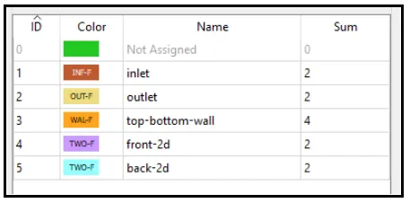
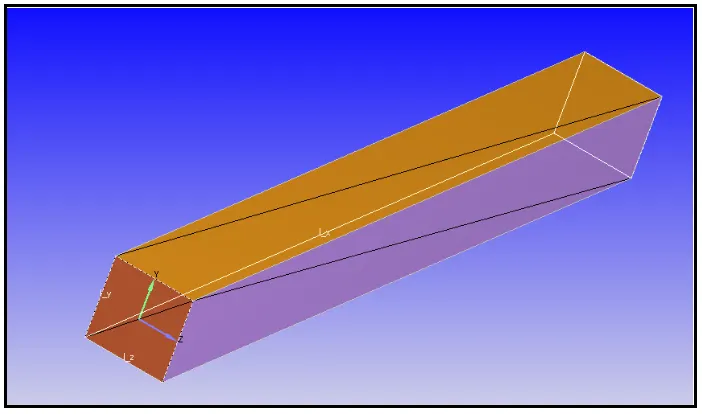
- After assinging the boundary conditions we need to assign the regions for al the boundaries.
- We need to create a region to initialize the setup.
- The initial pressure and then the Inlet pressure should have to be same.
- After that we need to uncheck the turbulence model. In this simulation we know that the flow is laminar so we don't need a turbulence model here.
- Output/Post processing
In this part we need to choose the variable which we want to plot.
Solution:
- After setting up the case in Converge, we have to save the setup file
- Aftet that we have to export the input files.
- After exporting the files we have to open CYWIN to perform the simulation.
- In the CYGWIN, we need to choose the directory at where we exported the input files.
- Then we have to copy and paste the location of intelmpi\converge.exe.
Results:
Mesh Image :
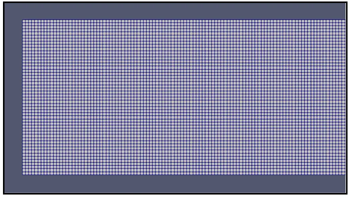
Mass flow rate plot :
Inlet:
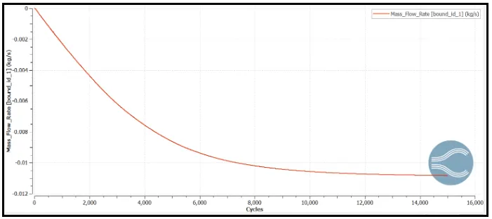
Outlet:
Pressure plot :
Inlet :
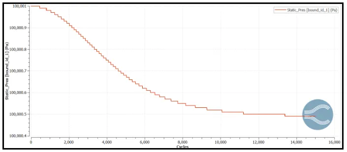
Outlet :
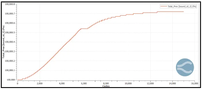
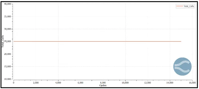
Total cells:
Velocity plot :
Inlet:
Outlet:
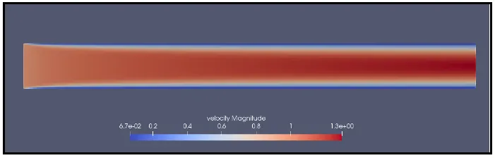
Velocity Contour :