Week 1 Challenge
1st Answer
Aim : Create a new project and name the project.
Tools used :
~ File toolbar
~ project icon
Procedure :
~ Click the file tool bar beside the architecture tool bar.
~ When you click the new bar in the file toolbar we get an project option.
~ Once you press project option you have to choose architecturial template to start your project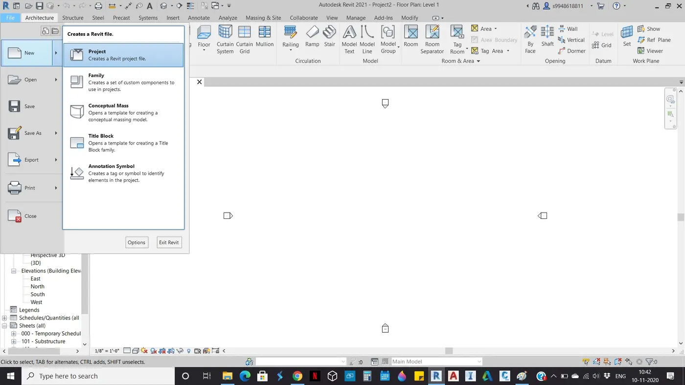
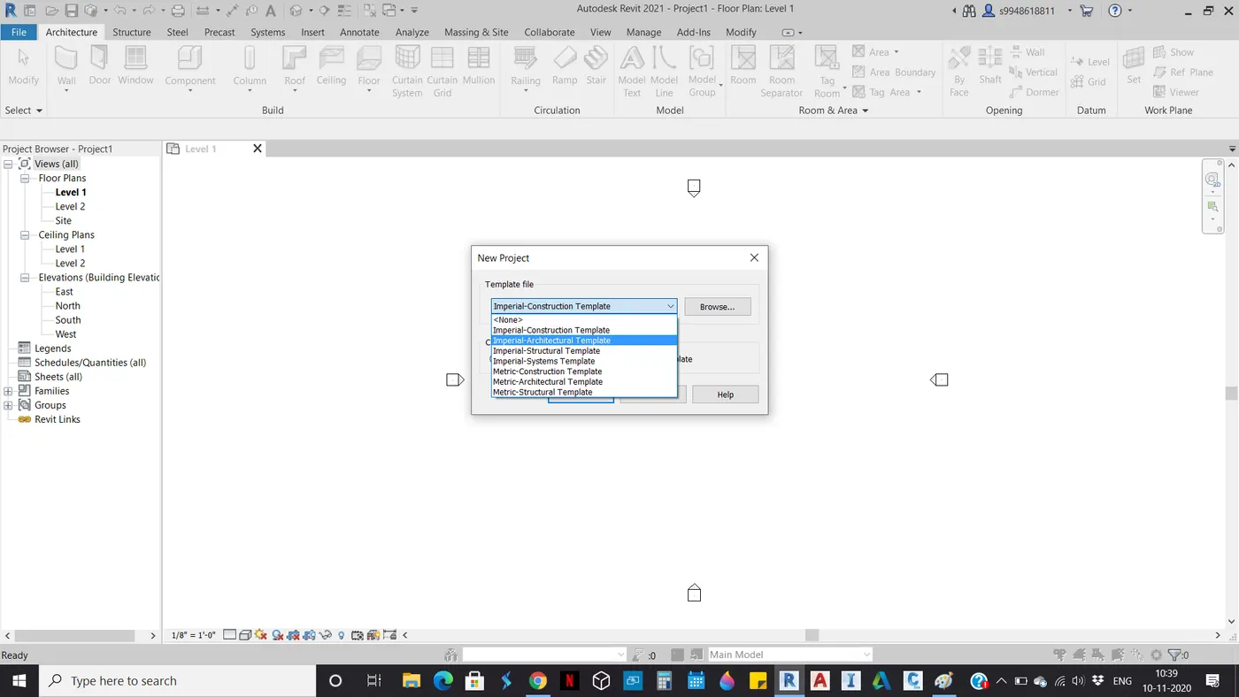
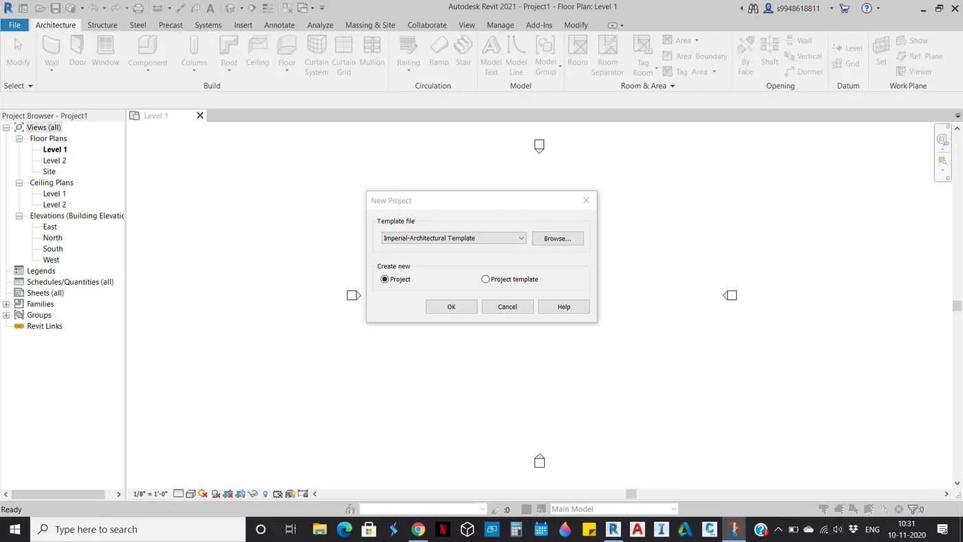
Result : Successfully created a project.
2nd Answer
Aim : To save a new project file in revit.
Tools used:
~ File tool bar
~ Save as option
Procedure:
~Once you press the file tab, you see the save as option.
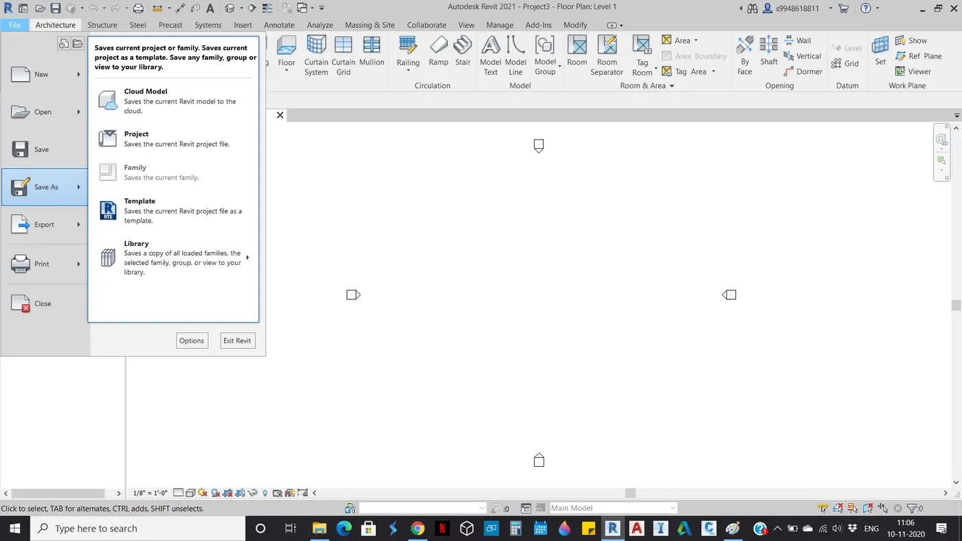
~Once you press the save as option, you have to type in the appropriate name for your project. Then press save option.
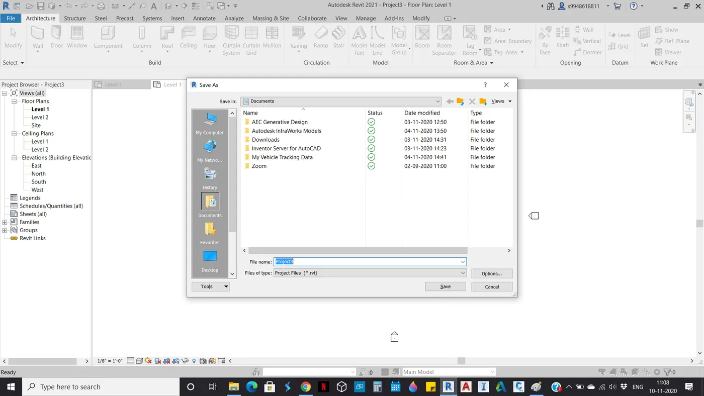 Result : The file is saved successfully.
3rd Answer
Aim: To create an rectangular layout of wall of about 40'0" X 35'0"
Tools used:
~ Wall
~ Line
~ Rectangle
Procedure:
~Click the wall command on the architecture toolbar.
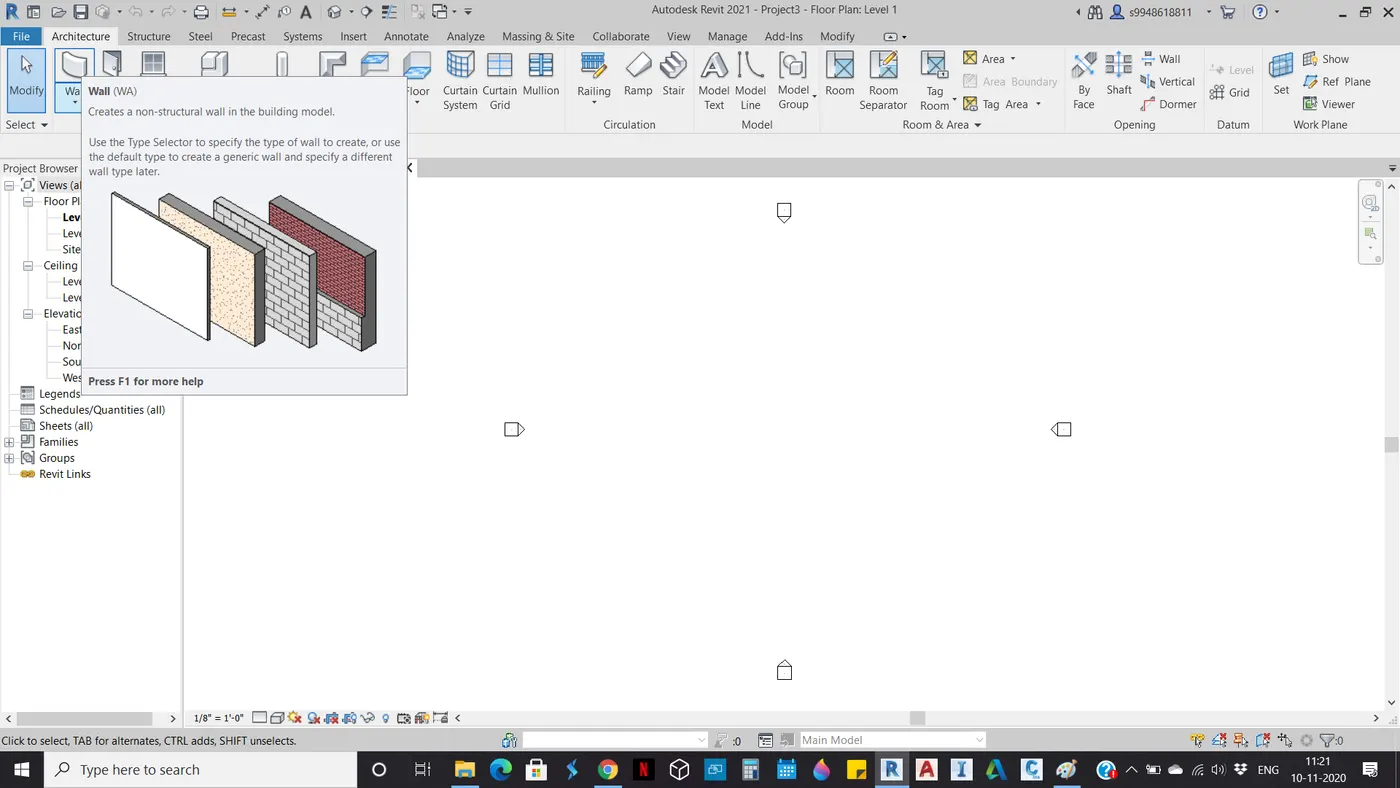
~ Draw a rectangle using the wall command.
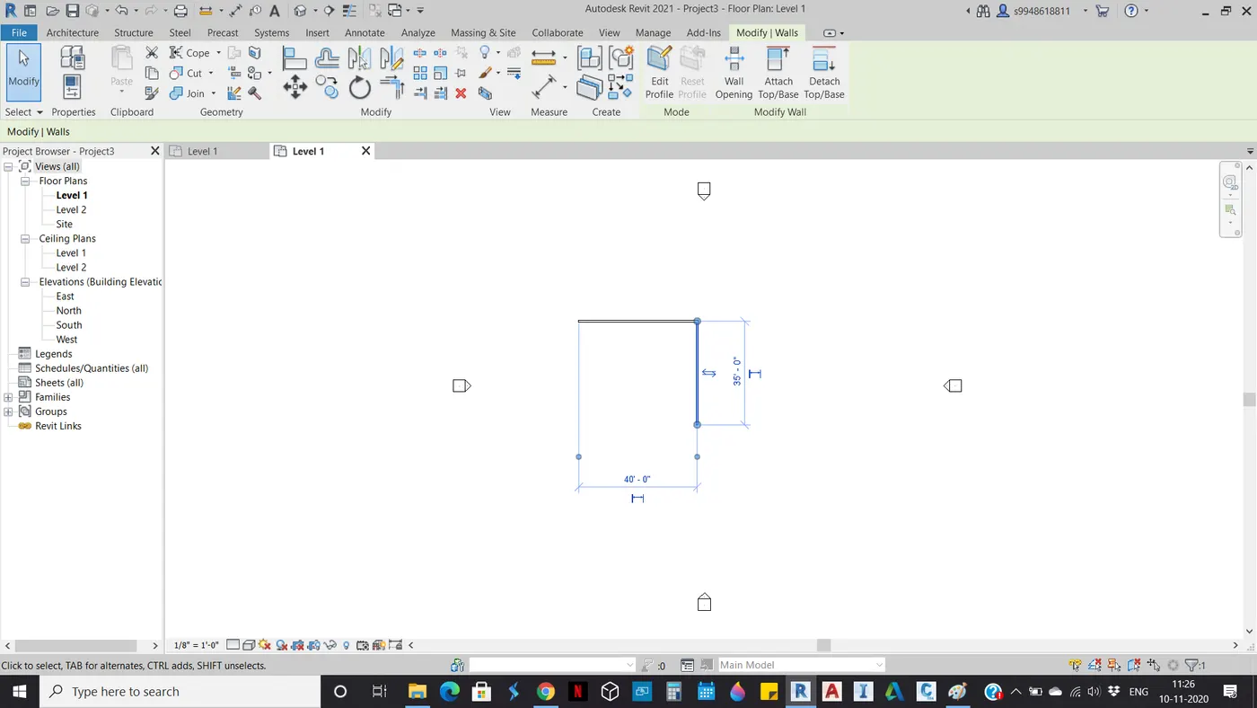
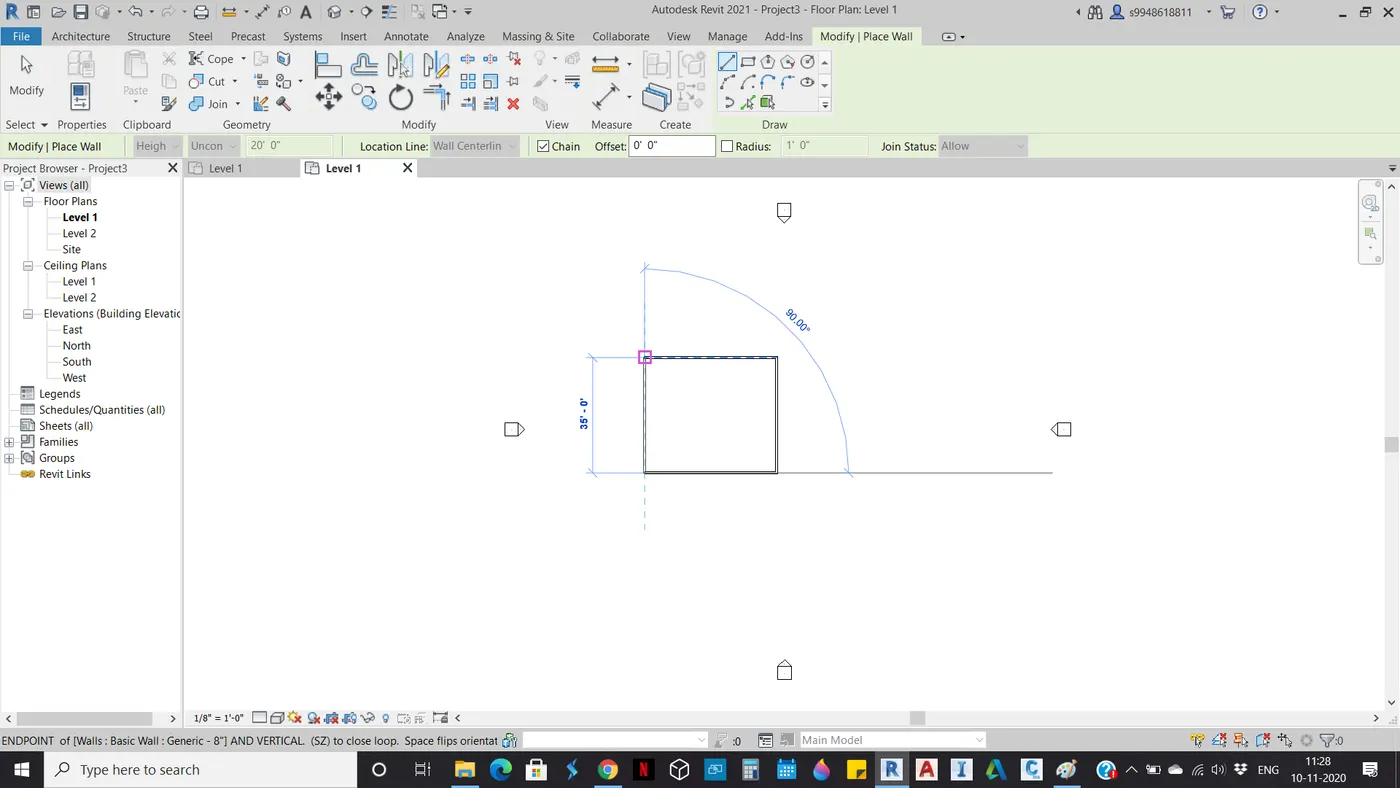
Result: A rectangular wall of dimension 40'-0" X 35'-0" was successfully drawn.
4th Answer
Aim: Use annotate tool bar to add dimension to the layout
Tool Used:
~ Annotate tool bar
~Aligned option
Procedure:
~ Press the annotate tool bar, then you see the aligned option. Once you press on the ends on one all and then add the dimension to the layout.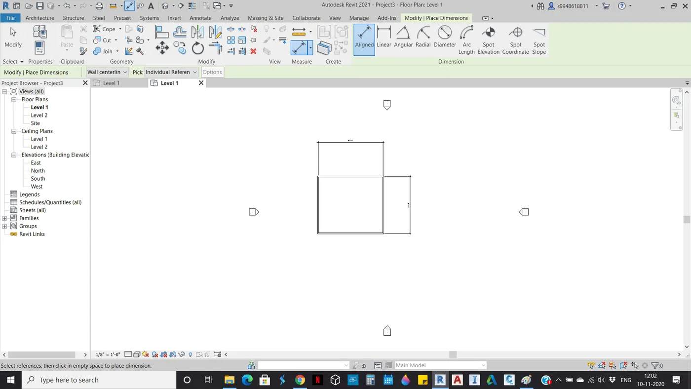
Result: The dimensio are assigned to the layout.
5th Answer
Aim: Switch to different wall types using properties browser.
Tools used:
~ Property tools
~ Edit type tool
Procedure:
~Firstly we need to draw a wall
~Now click any one side of the wall, automatically you will be directed to the modify walls tool
~Now in the type tool box select any one of the desired wall type
~click ok
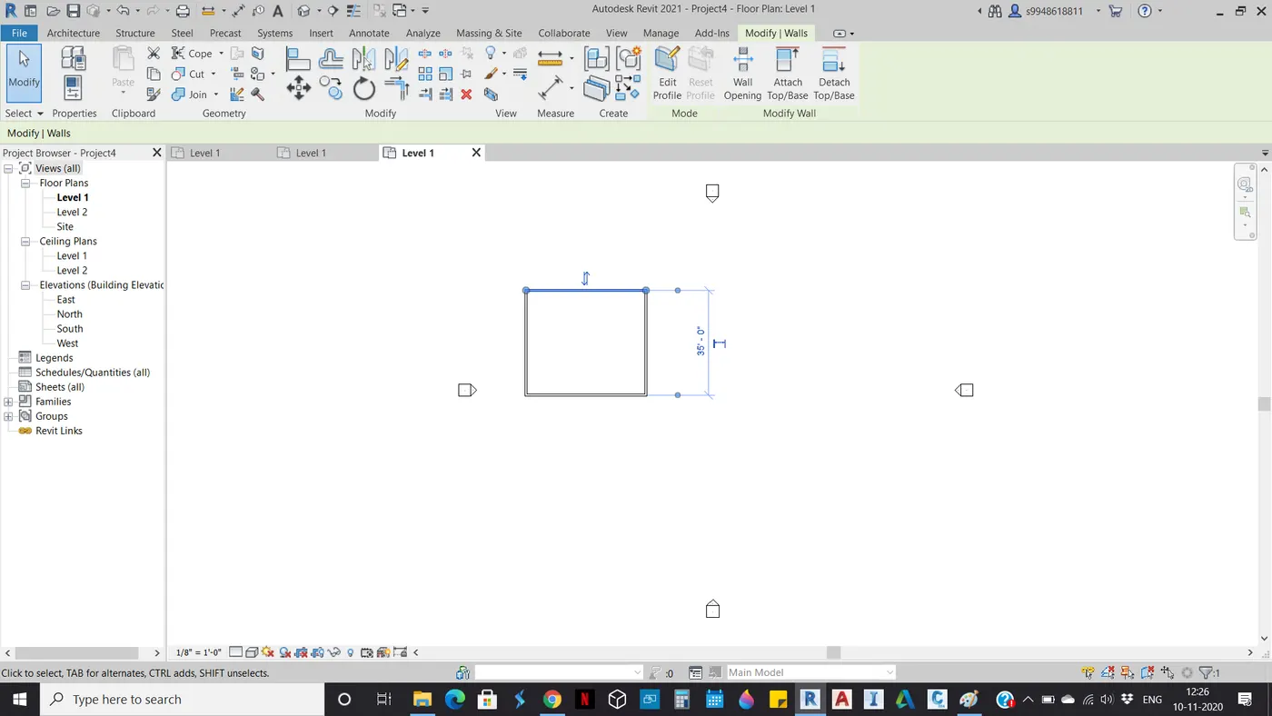
Result: Switch to different wall type is done successfully.
6th Answer
Aim: To 3D view from the view tool bar and save with appropriate name
Tools used:
~Wall tool
~Default 3D view tool
Procedure:
~To create a 3D view, we have to draw a wall of desired dimensions.
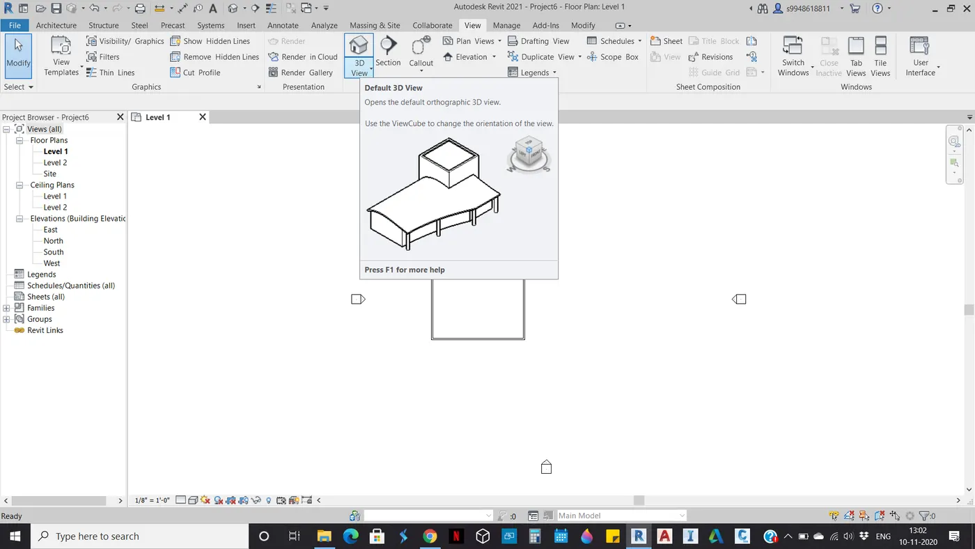
~Now click the 3D view tool, then our 2D wall changes into 3D model.
~Now to save the file, we need to go to file toolbar and click on save as option. You get an option to name the project appropriately.
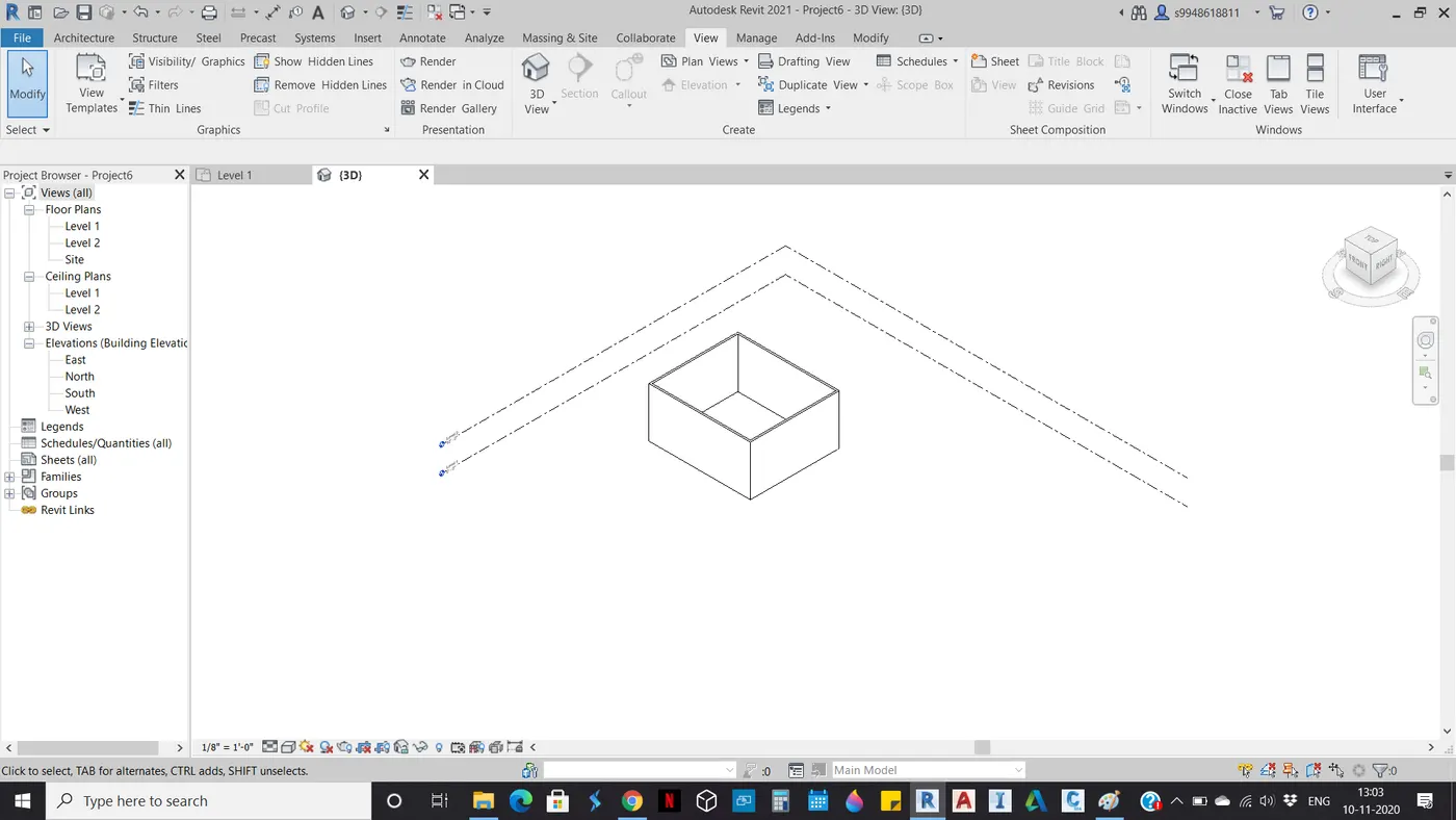
Result: 3D view is created and saved.
7th Answer
Aim: To navigate the 3d model using view cube.
Tool Used:
~View cube
Procedure:
~ After compltion of the drawing of the layout of walls, we need to click on the view cube and rotate it according to the view required.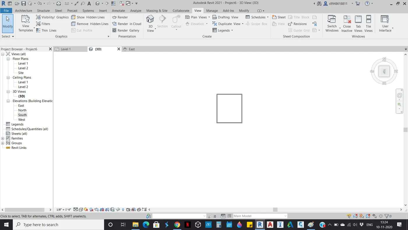
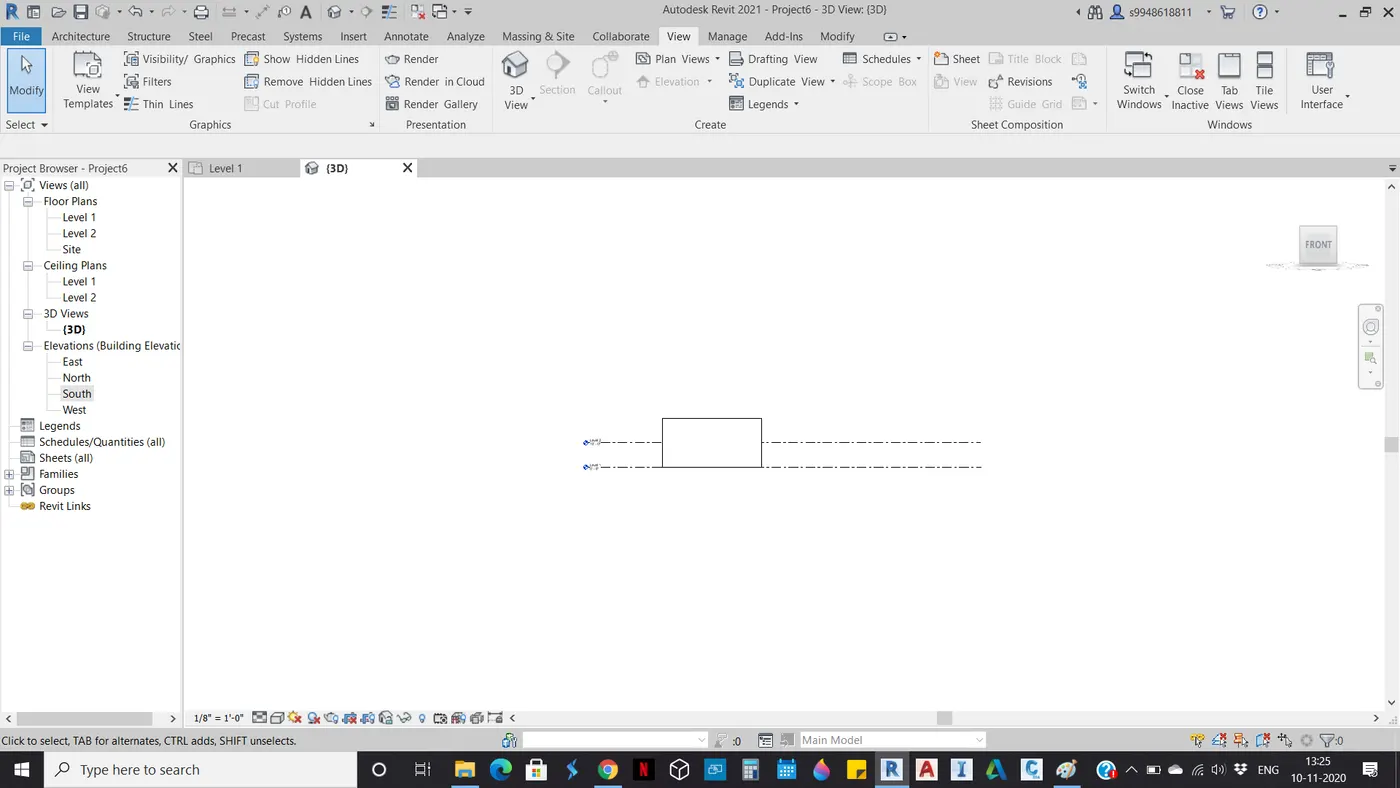 Result: The 3D model using view cube is done successfully
8th Answer
Aim: Switch model to shaded, realistic, hidden lines options using visibility settings.
Tools Used:
~Visual style tool
Procedure:
~Firstly consider a desired drawing
~Click on the visual style tool, and then we can see a box consisting of wireframe, hidden lines, shaded, colors and realistic.
~As we required to switch the model from hidden lines to shaded click on the option that we wish to convert.
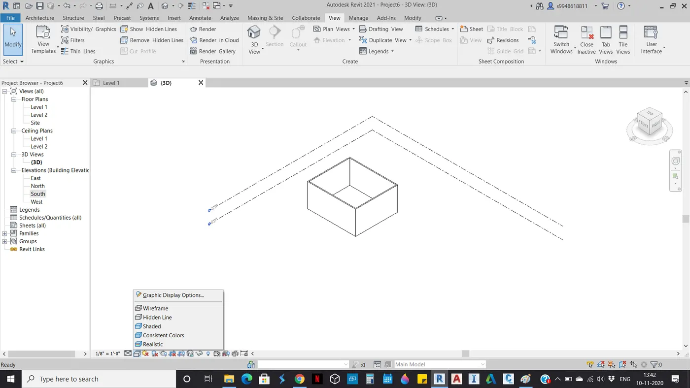
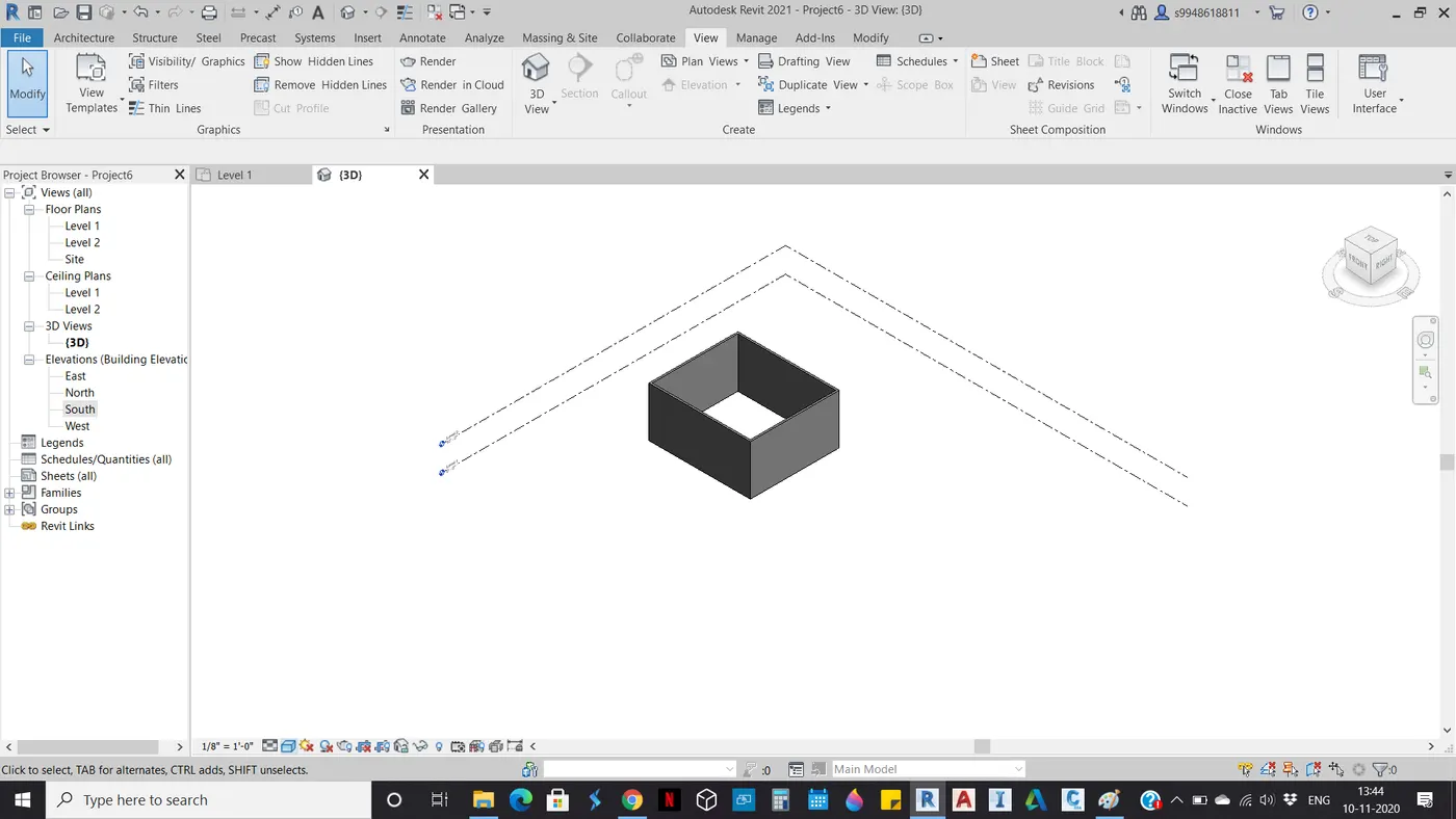
Result: Switch model to shaded is done successfully.
9th Answer
Aim: To turn the sunlight on and off to view shadings in the layout create.
Tools used:
~Sun setting tool
Procedure:
~Click on the sun setting tool which is available at the left bottom.
~There is an availability of two options, sun path on and off.
~ Click on then for the results.
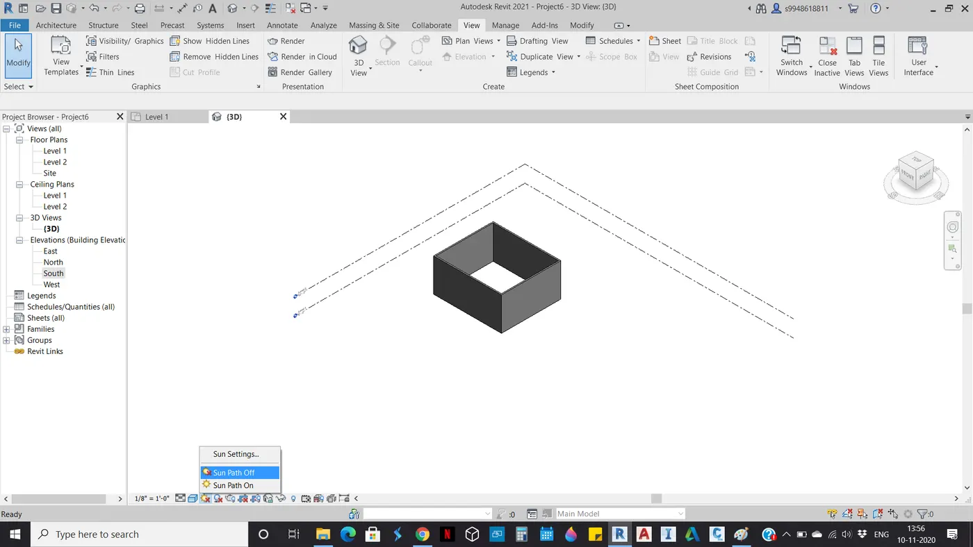
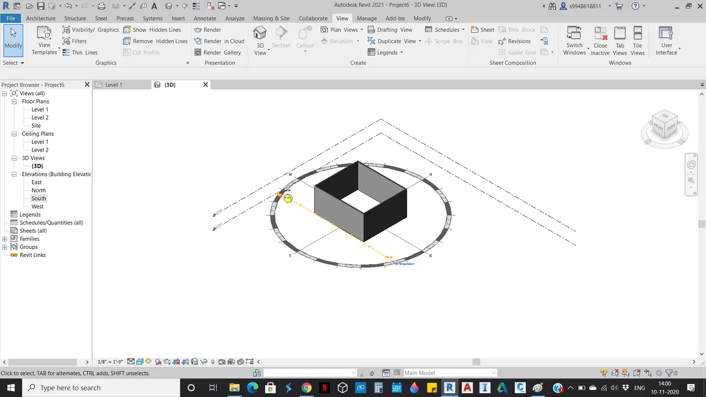
Result: The sunlight on and off is done successfully.
10TH Ans
Aim: Enter project settings, project name and project issue date using manage tool bar.
Tools used :
- Manage tool bar
- Project information tool
Procedure:
- Firstly click on the manage tool to open the manage tool bar
- Now we will find the project information icon under the setting section in manage tool bar
- By clicking the project information tool, a box is opened and we can enter the name, issue date and we can also change the projevt settings
Result: Enter project settings, project name and project issue date using manage tool bar done successfully.
- Analyse tool bar helps in creating revit models, this tool bar consists of many other options which help in load combinations, boundary conditions, loads and support system are one among the tools under this analyze tool bar where we get to adjust the model and add additional supports to the present model, it also verifies the analytical and physical model for the consistency. Space seperation, space naming and space tagging are also the options available assigning the names and numbers to the architectural rooms. Colour fill and energy optimization are the tools which help to know how far the present model is eco friendly and economical.
- links that support revit to link models are
- Link revit
- Link IFC
- Link CAD
- Link tropography
- DWF markup
- Point Cloud
- Coordination model
- Link PDF
- Link Image
- To link up multiple rivet models together we use Collaborate Tab that is any member among a particular team can haveacces to do change required that is very much usefulwhen a team consists different cader of people working around that is for a steel designer to a meachanical engineer . this helps people there to work with higher accuracy which will increase the efficiency .