Week 1 Challenge
- 1. Write the steps involved to upload a .std file through web mail?
Ans:
- First save the program file of Staad as .std file on appropriate path.
- Open the mail body of the web mail and attach the .std file.
- We can send the .std file to the web address and can open in Staad program.
- Name the different materials that can be designed using STAAD Pro.
Ans: We can assign following different materials to the geometry created in Staad for further analysis and design.
- Steel of different grades.
- Concrete
- Aluminium
- Stainless Steel
- Timber
- Is it possible to capture images in STAAD Pro? If yes how?
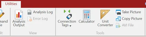
Ans: It is possible to capture the images in Staad Pro. Go to utilities tab and select “Take Picture” tab to capture the image of geometry, loading and postprocessing images. We can copy the pictures captures using “Take picture” tab and paste in the report wherever applicable.
- Name the three ways by which you can create a model.
Ans: We can process the modelling by following three ways.
- Analytical Modelling: To create geometry using commands.
- Physical Modelling: To create geometry using coordinates.
- Building Planner: To create geometry using structure vizard.
- Write the steps followed to assign properties in a model.
Ans: Properties to be assign properties to analytical model using following steps:
- Go to properties tab of Analytical modelling tool.
- To assign the properties through standard profiles, use section database tool of properties command.
- We can assign the property through define tab also by providing sizes to the standard profiles like rectangular, I, tube, circular sections and assign materials to these profiles.
- We can assign the properties through user table option also by feeding the section modulus values of built up section.
- 1. Name any six-design parameter involved in RCC design.
Ans: Following are the six design parameters used in RCC design.
- Selection of design code by CODE parameter.
- Specifying clear cover by CLEAR parameter.
- Specifying strength of concrete by FC parameter.
- Specifying grade of steel by FYMAIN & FYSEC parameter.
- Specifying length for design by LX, LY, LZ parameter.
- Specifying diameter of bars for reinforcement by MINMAIN & MINSEC parameter.
- Specifying type of member design by DESIGN BEAM/COLUMN parameter.
- What are the different cursor types available in STAAD Pro?
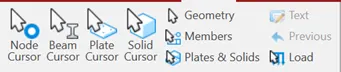
Ans: Following are the different cursor types used to select different elements of the geometry.
- Node cursor.
- Beam cursor.
- Plate cursor.
- Solid cursor.
- Geometry cursor.
- Members cursor.
- How will you generate different views for a model? State the steps involved.
Ans: After creating the geometry, following are the steps to create different views.
- Go to vies tab of command tab.
- In views tab different tools available for views selection like isometric, front, back, top, bottom, left & right etc.
- Selecting each view tool, we can see the views in modelling window of the geometry.
- By taking picture of the selected view, we can create different views of structures in report.
- Explain the procedure to define a “Simply Supported” condition in STAAD Pro.
Ans: Following is the procedure to define simply supported condition in Staad Pro.
- Select the node of the member where the support condition to be assigned.
- Go to support tab.
- Click on create support.
- Select the pinned support option.
- Assign the support to the node selected.
- Name any five topics that you will include while creating DBR.
Ans: Following are the topics majorly included in DBR:
- Introduction: Providing general description about the project.
- Structural Layouts: The general arrangement drawings of the structural systems provided in the project.
- Loads and combinations: Providing information about the loads considered in the project and load combinations considered as per ISO standards.
- Analysis and Design methodology: Providing analysis and design procedure and results of the same.
- Quality assurance plan: Providing information about quality control aspects followed in analysis and preparation of drawings.
- Appendices: Providing information about structural diagrams, loading calculations for wind and seismic and analysis model.
- Describe the term “Multi material design” of STAAD Pro.
Ans: The geometry created in the Software has influence with different structural materials like foundations are of RCC and superstructures are of Steel, RCC or timber. We can perform analysis and design of different materials after assigning material and design parameters respectively.
- 1. Name the structure systems in STAAD Pro? Explain each system?
Ans: Following are the different structural systems for which analysis and design can be performed.
- Space: Geometry, loading and deformations are 3 dimensional and any type of joint restraints can be assigned.
- Plane: Geometry, loading and deformations are 2 dimensional and any type of joint restraints can be assigned.
- Frame: Geometry is 2 dimensional, loading and deformations are perpendicular to XZ direction, and any type of joint restraints can be assigned.
- Truss: Truss system cannot take bending and designed for axial loads only. Geometry, loading, and deformations are 3 dimensional and Pinned type of joint restraints can be assigned.
- Explain the coordinate system adopted in STAAD Pro software.
Ans: The coordinate system adopted in Staad Pro are global and local coordinate system. In global coordinate system the direction of loading will not change after application. However, in local coordinate system the loading along the length i.e. local X direction remains the same but the other two direction changes depends on member orientation.
3. Elaborate DBR and its uses.
Ans: DBR is the term used for design basis report. It generally prepared to specify and compile the data required for analysis and design of the structural elements of the project. DBR helps to clearly depict the assumptions and specifications that are used to develop design and construction documents. It also help to avoid scope creep that affect project schedule and budget constraints to complete the project in requisite timeline.
4. Explain the different types of analysis options in STAAD pro.
Ans: Following are different analysis options available in Staad Pro.
- Perform analysis: Generally used for primary load cases.
- P-Delta analysis: Used for iterative nonlinear analysis which involve design for lateral load cases like seismic forces.
- Perform cable analysis: In this each member is assigned as cable and this is also an iterative analysis.
- Perform imperfection analysis: This method is used for the analysis of members having requirement of camber.
- Nonlinear analysis: This is again iterative analysis method used in space and frame systems.
- Generate floor spectrum analysis: This method used in high rise buildings where the floors need to be assigned as diaphragms.
- Direct analysis: This is nonlinear iterative analysis carried out based on AISC guidelines.
- Pushover analysis: This method used for carrying out analysis for seismic forces.
- Explain the difference between Fixed and Fixed But condition.
Ans: The fixed condition assigned to joint has restraint in rotational as well as translational direction. However the fixed but condition assign to joint has rotational restraint but release in translational direction.
Practical
1. Create a STAAD Model with the following Specification
a. A beam of span 16m
b. Support: Fixed on one end and Roller support (Horizontal) on the other end
c. A point load of 50 kN at the mid-point.
d. Draw SFD and BMD using software.
Aim: To create Staad Model of beam spanning 16m.
Introduction: A beam is created in analytical model space for the given span and loading of 50kN at midpoint of the beam.
Procedure:
- Modelling:
- First in geometry coordinates are given as ‘0’ and 16m in x direction.
- Support conditions are assigned as fixed at one end and fixed but roller in X direction using support tab.
- Member sizes and materials are assigned using property and materials tab.
- Loading:
- Load case created by addition of Dead Load.
- In the created load case, using member load option, 50kN load is created in global downward direction.
- The load created is assigned to the member using assign to view command.
- Analysis:
- Perform analysis command is used to analyse the beam.
- In postprocessing tab beam results are viewed for the given loading.
- SFD & BMD diagrams:
- Using labels option, the scale for shear force and bending moment diagrams is adjusted.
- The values are displayed using annotate command in post processing mode.
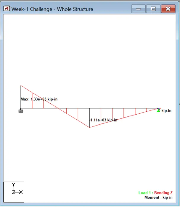
Result: The SFD and BMD is created using various commands listed above for 16m span beam.