Week 1 Challenge
1. Truss type reasoning
AIM: To determine the most efficient type of Truss (A or B) on carrying gravity load.
OBSERVATION: We see that Truss A is Pratt truss and Truss B is Howe truss.
- Pratt truss:
It is a truss having vertical members between the upper and lower members and diagonal members sloping toward the center. Pratt trusses are commonly used in long span buildings ranging from 20 to 100 m in span. In a conventional Pratt truss, diagonal members are in tension for gravity loads. This type of truss is used where gravity loads are predominant.
It s also important to note that in Pratt Truss Design, and most Truss design for that matter, is that the members have their end fixities set to pinned. This ensures that the force is all transferred in either compression or tension, with little (theoretically, none) transferred in the form of bending moment force.
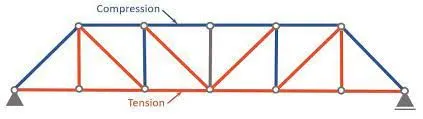
A Pratt truss includes vertical members and diagonals that slope down towards the center, the opposite of the Howe truss. The interior diagonals are under tension under balanced loading and vertical elements under compression.
- Howe truss:
It is a truss bridge consisting of chords, verticals, and diagonals whose vertical members are in tension and whose diagonal members are in compression.
It is a structural system which can carry loads with relatively long spans compared to beams. It's mainly used as bridge structure carrying traffic and dead load and distributing it to its supports. The Howe truss is characterized by its diagonal members, which are inclined with the same angles.
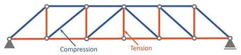
RESULT: So the Truss A (pratt truss) is most efficient when the gravity loads are applied when compared compare to the Truss B (howe truss)
2. Deflection shape & Bending Moment Drawing (Qualitative approach)
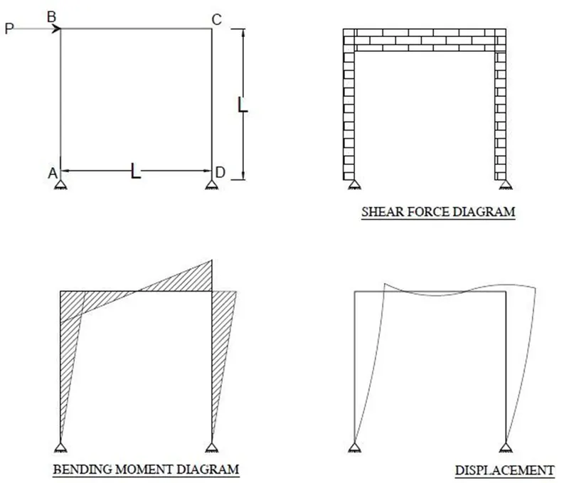
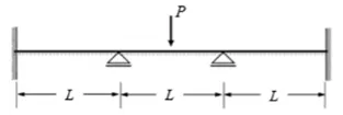
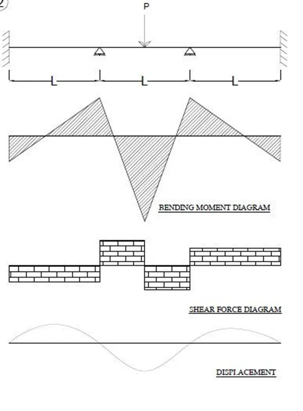
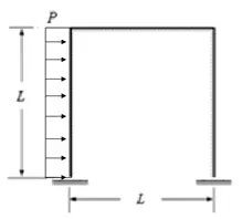
AIM: To draw the deflected shape and bending moment drawing for the beam and Frame shown (E & I are constants).
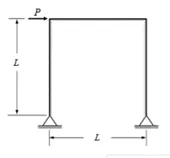
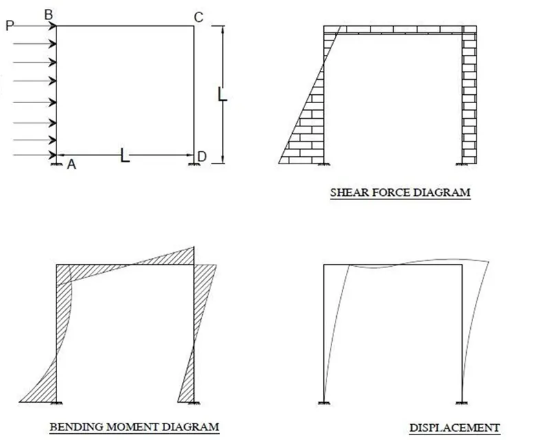
1. Horizontal point load in frame.
RESULT:
2. Point load at fixed ends and two pinned support in between.
RESULT:
3. UDL in on of the frame.
RESULT:
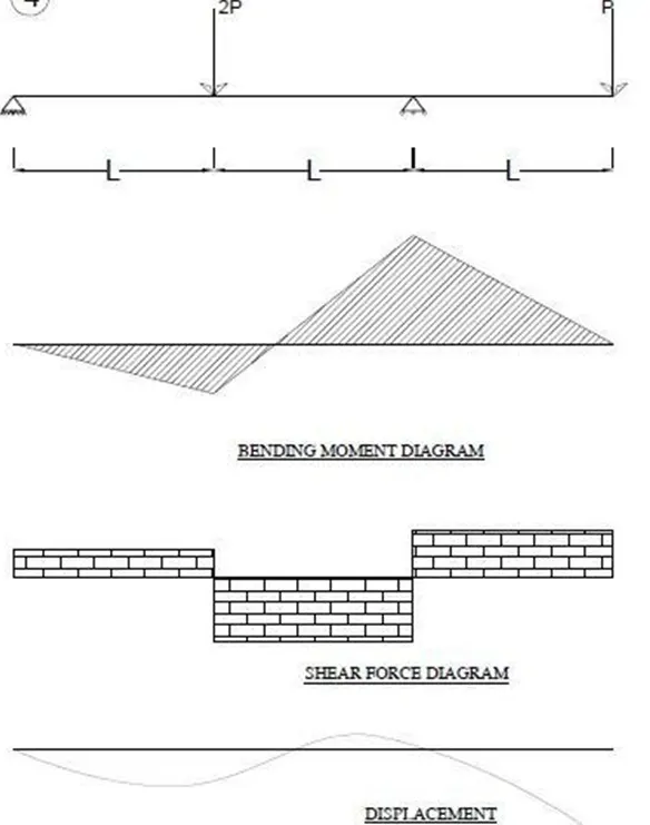
4. Point fixed and rooling support and point loads at the end of hanging frame.
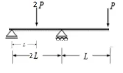
RESULT:
3. Determine MOI, Weight, C/S area of sections below
AIM: To determine the MOI, Weight, C/S area of the chennel and I section.
OBSERVATION 01:
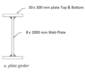
On using the formula,

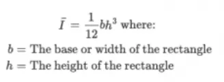
RESULT 01:
MOI ALONG Iz=5442066666.6667 mm4
MOI ALONG Iy=135042666.6667 mm4
Weight per meter= 204.1 kg/m
OBSERVATION 02:
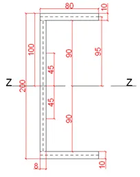
b=80
h=200
tw=8
tf=10
On substuting this in the formula we get the MOI,
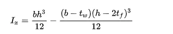
Ix =1.83413 x107 mm4
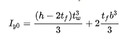
Iy = 1.84324 x106 mm4
Weight = volume × density
density of steel is 7850 Kg/m3
volume = web height × flange width × thickness.
Weight per meter= 23.84kg/m
RESULT 02:
MOI ALONG Iz=1.83413 x107 mm4
MOI ALONG Iy=1.84324 x106 mm4
Weight per meter= 23.84kg/m
OBSERVATION 03:
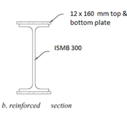
RESULT 03:
MOI ALONG Iz=18540000 mm4
MOI ALONG Iy=1420000 mm4
Weight per meter= 74.34 kg/m
OBSERVATION 04:
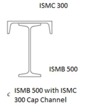
RESULT 04:
MOI ALONG Iz=64180000 mm4
MOI ALONG Iy=81630000 mm4
Weight per meter= 74.34 kg/m
4. Load calculation problem
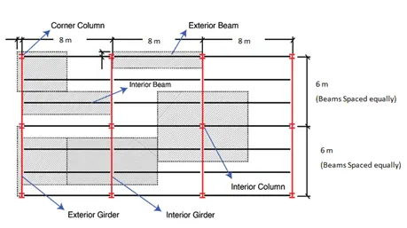
AIM: To Calculate the load on interior beam, Exterior beam, Interior Girder and exterior girder having Floor Load of 10kN/m2
OBSERVATION:
RESULT:
INTERIOR COLUMN=49.04 KN
CORNER COLUMN=12.26 KN
INTERIOR BEAM=20 KN/M
EXTERIOR BEAM=10KN/M
INTERIOR GIRDER=22.5KN/M
EXTERIOR GIRDER=20 KN/M
AIM-To Calculate the length difference at 40 ºC and its total length Assuming a bridge, made of steel.
OBSERVATION:
Initial total length (L0) = 2000 m
T0= -20 ºC
T= 40 ºC
Coefficient of Thermal expansion of steel (α)= 12x10-6/°C
On substuting in formula,
ΔT=T–T0=40–(−20)=40+20=60 °C
ΔL=α⋅L0⋅ΔT=12x10-6x2000x60=1.44 m
L=L0+ΔL = 2000x1.44 =2880 m
RESULT:
length difference= 12x10-6/°C X 2000M X 40°C
TOTAL length difference at 40 ºC IS 0.96M