Week 1 Challenge
Q1.
1. Write the steps involved to upload a .std file through web mail?
ANSWER:-
The procedures for sending a.std file over web mail are as follows:
Locate the share option on the introductory screen of the STAAD Pro software by opening it.
Select the send mail option after clicking the share button.
Find the standard file on your computer and email it after that.
2. Name the different materials that can be designed using STAAD Pro.
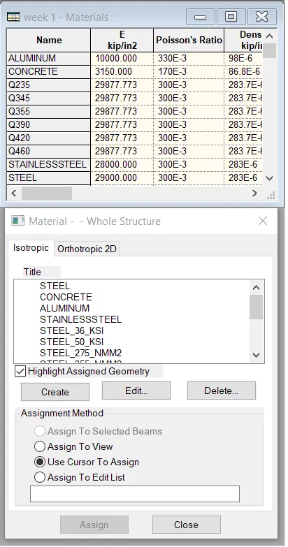
ANSWER:- To create a new isotropic material definition for use with your model, use the following procedure.
You may want to set the input units to a familiar set of units for defining materials before creating a new material definition.
- Select the Materials page in the Analytical Modeling page control bar.
The Material - Whole Structure dialog and the Materials table open.
Different materials that can be designed using STAAD Pro. are as below :-
- Concrete.
- Steel.
- Aluminium.
- Timber.
- Composite sections.
3. Is it possible to capture images in STAAD Pro? If yes how?
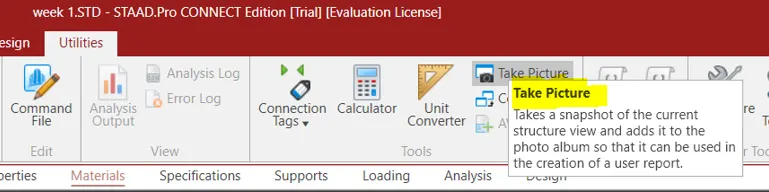
ANSWER:- YES, capturing images in STAAD Pro is possible. We can take pictures of models and structural results in staad pro using the take picture command, the command is available in the utility panel with a camera logo.
In STAAD Pro, it IS possible to take pictures.
Using the take picture command, which is available in the utility panel and has a camera logo, we may take pictures of models and structural results in Staad Pro.
4. Name the three ways by which you can create a model.
ANSWER:- Being a collection of data (points and other information), 3D models can be created manually, algorithmically (procedural modeling), or by scanning
Three ways by which you can create a model in STAAD pro are as below;
- Analytical model.
- Physical model.
- Building planner model.
5. Write the steps followed to assign properties in a model.
ANSWER:-
- Head over to the properties panel.
- Select Materials.
- Choose your preferred material from the list, which includes stainless steel, concrete, steel, and aluminium.
- Check the assignment technique after that based on your preferences, such as assign to view or using the cursor.
- After selecting the radio button, give your model the material property.
Q2.
1. Name any six design parameter involved in RCC design.
ANSWER:-
Following are the six design parameters used in RCC design:
- Cover in clear
- compressed FC durability of concrete
- Steel's FY Tensile Strength
- Maximum bar diameter
- Code of conduct
- Conrete end design
2. What are the different cursor types available in STAAD Pro?
ANSWER:-
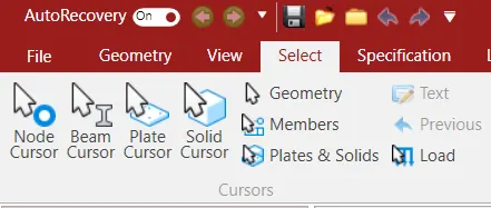
The following is a list of the various cursor kinds that are offered by STAAD Pro :-
- cursor for nodes.
- cursor plates
- cursor beams
- Solid cursor and plates.
- cursor is loaded.
- a solid cursor.
- member's physical cursor.
- cursor for geometry.
3. How will you generate different views for a model? State the steps involved.
ANSWER:-
First go to view option in the ribbon there we can get option like as below;
- Top view
- Isometric view
- Front view
- Left view
- Right View
- Botttom view
- Back view
4. Explain the procedure to define a “Simply Supported” condition in STAAD Pro
PROCEDURE:-
Select the support command by going to the tool palette command.
choose the create-support command.
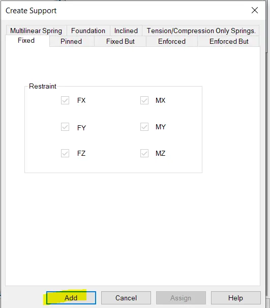
There are options like fixed support, pin support, and fixed but required support.
cables to provide support Leaning support
5. Name any five topics that you will include while creating DBR.
ANSWER:-
First of all lets understand what is DBR? So the DBR is the Design Brief Report.So basically DBR is a short brief of what you are going to make,why you are going to make,where you are going to make. In short it is a core detail of our project. So the five topics that will include creating DBR is listed below:
- Name of the project and the location of the project.
- Structural Layout.
- Introduction to the construction methodology.
- Quality Assurance and Quality Control.
- Budget of the Project.
6. Describe the term “Multi material design” of STAAD Pro.
ANSWER:-
- It is used for 3D model generation, analysis and multi -material design .
- The STAAD .Pro supports several steel , concrete and timber material in a seprate member
- This seprate member will cordinate and the formed in to a structure
Q3.
1. Name the structure systems in STAAD Pro? Explain each system?
ANSWER:-
The following are the structure systems in STAAD Pro:
Frames in space.
Aircraft frames.
Trusses.
EXPLANATION:-
1.SPACES FRAME:
Space frames are essentially three-dimensional truss-like constructions that are intended to transfer weights over extended distances without the use of intermediate supports. The space frame structures are useful structurally and are lightweight and rigid in nature. It is inexpensive to transport.
2. AIRCRAFT FRAME:
RCC or steel frames are used in aeroplane construction. It is a two-dimensional construction made of straight pieces that are joined together by hinged or rigid connections.
TRUSSES: 3.
The structural components are arranged into triangular shapes, which can support loads in both compression and tension, to make trusses.
2. Explain the coordinate system adopted in STAAD Pro software.
ANSWER:-
The X, Y, and Z co-ordinates systems are the ones used in STAAD Pro software.
Therefore, the basic coordinates used in The STAAD Pro program are as follows:
Global Axis: The co-ordinate system primarily fixes the global axis.
Local Axis: The nature of the local axis is variable. The global axis cannot be changed, just the local axis.
like the STAAD Pro programme. In essence, it uses a standard cartesian coordinate system, where Y is the global axis and is oriented upward. According to the illustration provided below, the height of the building is always parallel to the global Y-axis:
3. Elaborate DBR and its uses.
ANSWER:-
Therefore, the DBR (Design Brief Report) is essentially a project management document that contains various details on the building of the structure. This DBR is a thorough report that goes into great depth about the current construction project. In outlining the Client's requirements for the construction work, it specifies the last step in the process. This report basically contains all of the significant structural information that is pertinent to, or we might say that is related to, the project, such as a client description, site information, special requirements, if any, technical requirements, components needed, project requirements, and other construction-related issues.
4. Explain the different types of analysis options in STAAD pro.
ANSWER:-
The different types of analysis options in STAAD Pro software are listed below:
- Linear Elastic analysis.
- P-Delta analysis.
- Buckling analysis.
- Pushover analysis.
5. Explain the difference between Fixed and Fixed But condition.
ANSWER:-
Fixed condition:-
Fixed condition in the STAAD Pro software is the condition where all the degrees of freedom that is horizontal or vertical or moment are fixed or we can say these coditions are restrained we cannot change accordingly. Those condition we can say are the fixed conditions.
Fixed-But condition:-
And as for the fixed-end condition we can say that this condition can be customized its end conditions accordingly. In this condition we can change the end condition it is not restrained.We can release some of the required degree of freedom.
Practical
1. Create a STAAD Model with the following Specification
a. A beam of span 16m
b. Support : Fixed on one end and Roller support(Horizontal) on the other end
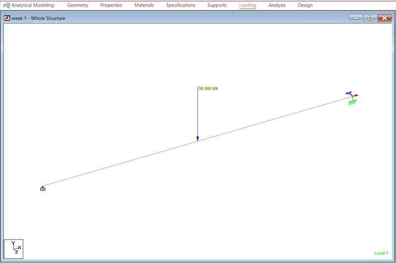
c. A point load of 50 kN at the mid-point
d. Draw SFD and BMD using software
PROCEDURE:-
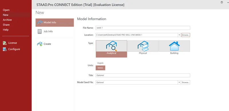
- Open the STAAD pro Software and Create a New Model
- The first step is to initiate the project in staad.pro
- The same can be done by clicking on the new option available on the staad intro screen.
- After clicking on the new model, you can feed the project details.
- Also, you will be asked to specify a location within your system.
- Then, click on create to start a new project.
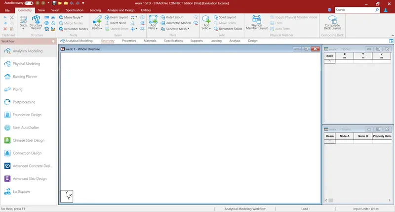
Now, draw the required-span beam.
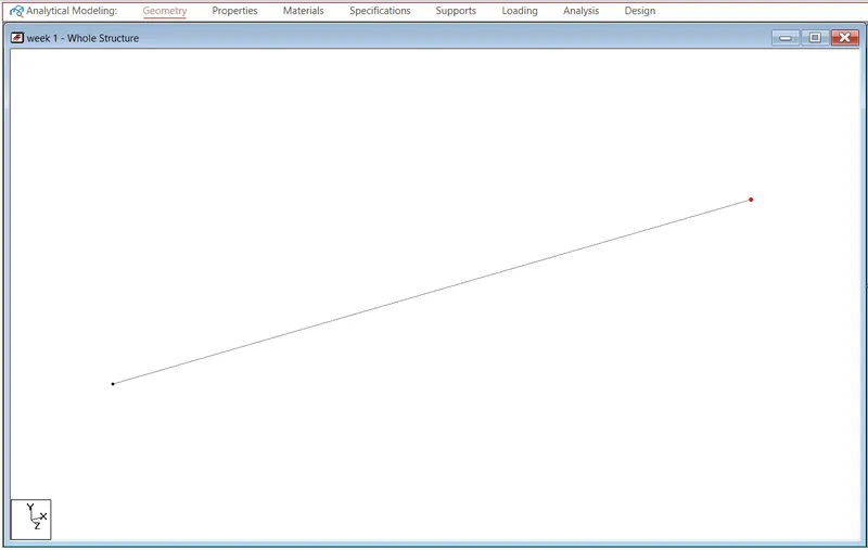
Create the initial node at X-0, Y-0, and Z-0 in geometry to model the suggested beam.
Then, by going to the node cursor, choose the newly created node.
Ctrl + C and Ctrl + V.
Press enter after entering a span length of 16 metres in the X direction.
Once the appropriate beams' two ends have been constructed, go to add beam and choose the first node, then the second, to make the beam of the desired length.
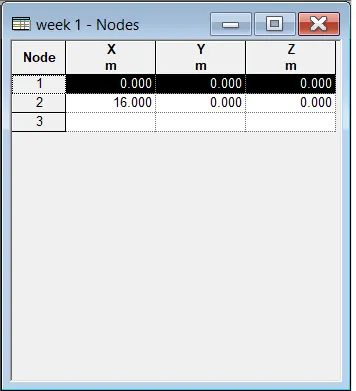
Nodes

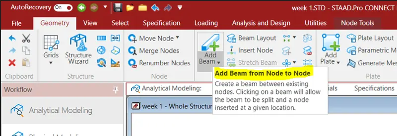
Beam
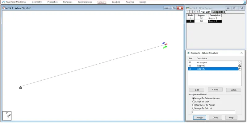
- Assign Support Conditions
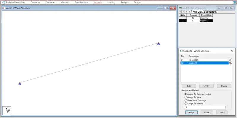
- Go to support>add>fixed>select one node>assign to selected nodes>enter.
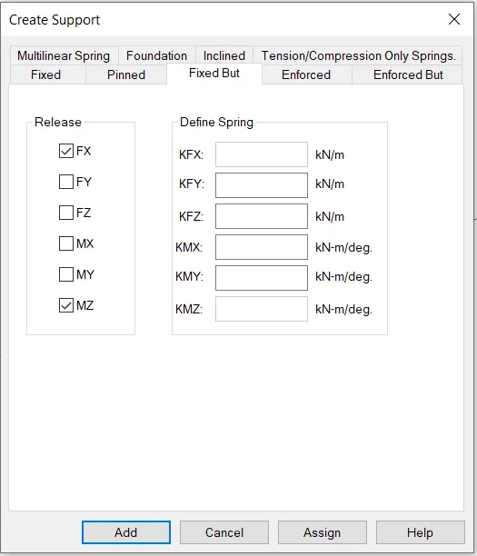
- Similarly, create another node>fixed but>release moments and horizontal restraints>ok>select the other node>assign to selected>ok.
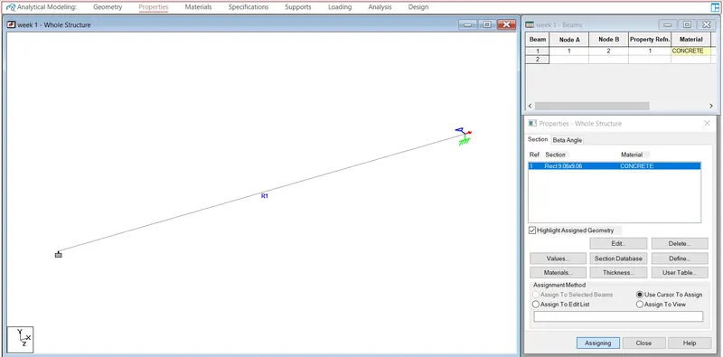
- give properties to the beam with and thickness
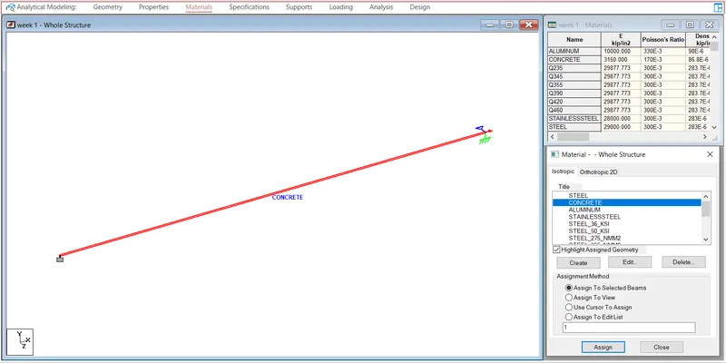
- give materials to the beam as a concrete
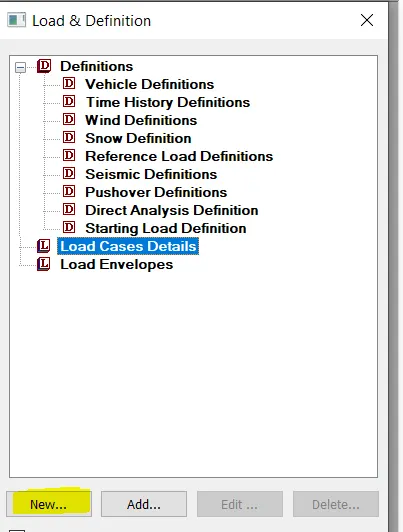
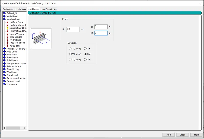
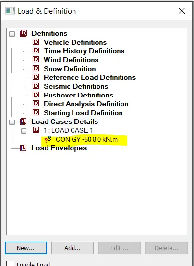
- Give the Proposed Load a name.
Enter loads>create>member load>globa Y>-50KN>d1-5, d2-5 in the menu.
OK.
Select the load and beam, then click the assign to selected>apply>ok radio option..
- Run the Analysis :-
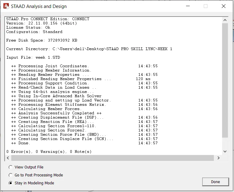
- After this, select the analysis method that is perform analysis from the design and analysis panel.
- Once you are done with setting up the analysis method, go ahead and run the analysis from the analysis and design panel.
- Wait some time for the analysis to get complete and look for errors and warnings.
- If there are no errors or warning signs upon completion of the analysis, you're good to go.
Sketch SFD and BMD :-
- Go to the post-processing mode now, choose the load cases, and then click Apply and OK.
- All of the analysis results will then be shown instantly on your screen.
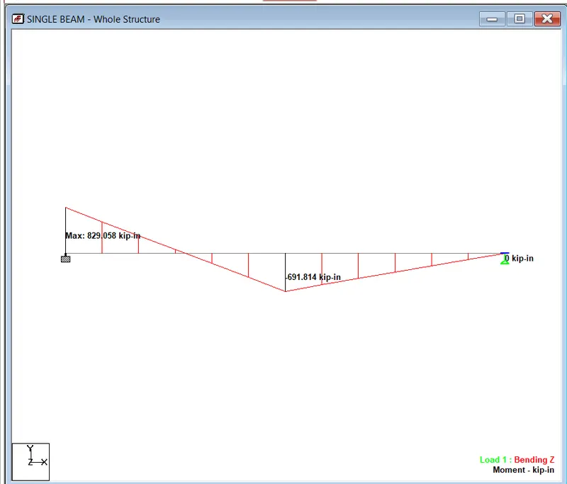
- For the shear force graphic, select Beam Results>Mz for bending moment.
- In order to view the values alongside the diagrams as inserted below, make sure to check the annotate option:
Shear Force Diagram
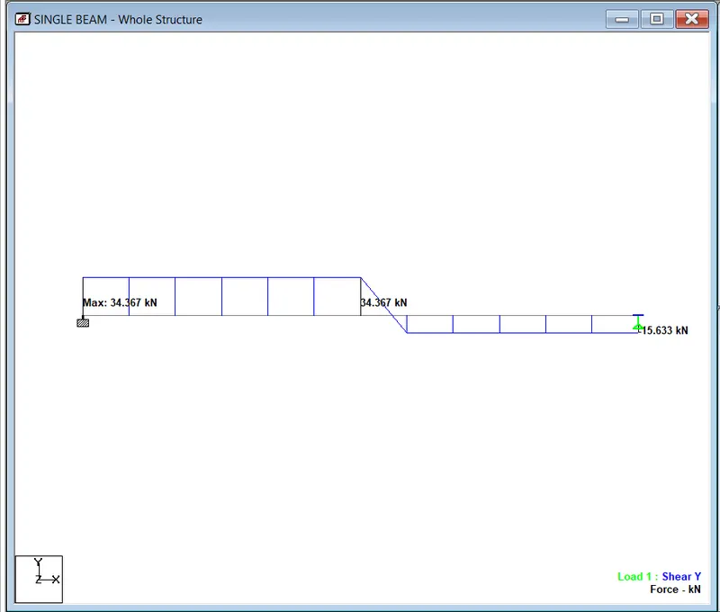
Bending Moment Diagram