Week 1 Challenge
QUESTION:-
1. 1. Write the steps involved to upload a .std file through web mail?
2. Name the different materials that can be designed using STAAD Pro.
3. Is it possible to capture images in STAAD Pro? If yes how?
4. Name the three ways by which you can create a model.
5. Write the steps followed to assign properties in a model.
2. 1. Name any six design parameter involved in RCC design.
2. What are the different cursor types available in STAAD Pro?
3. How will you generate different views for a model? State the steps involved.
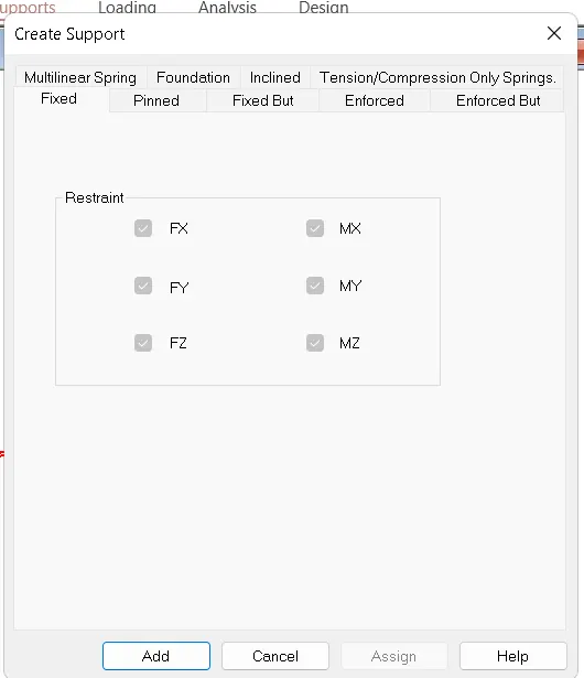
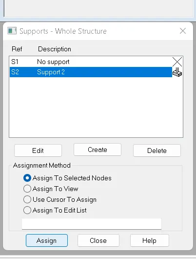
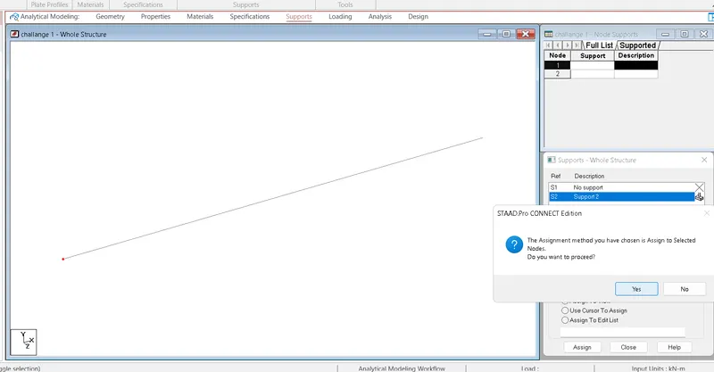
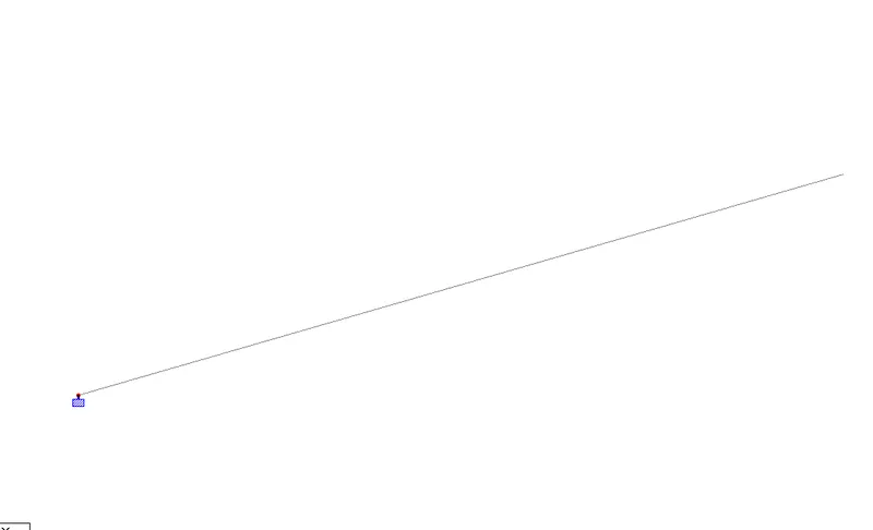
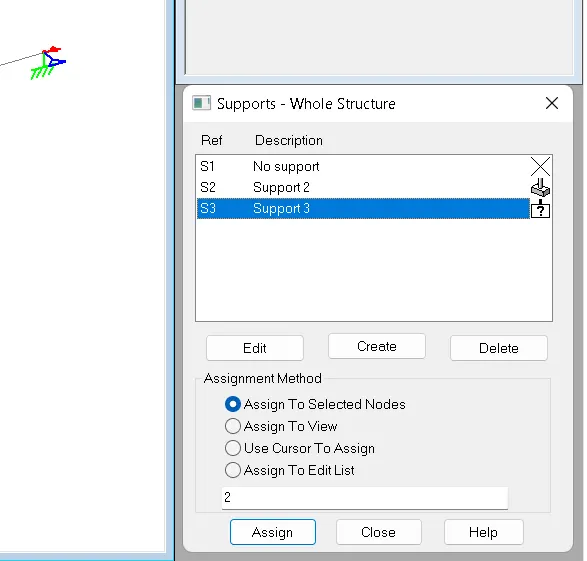
4. Explain the procedure to define a “Simply Supported” condition in STAAD Pro
5. Name any five topics that you will include while creating DBR.
6. Describe the term “Multi material design” of STAAD Pro.
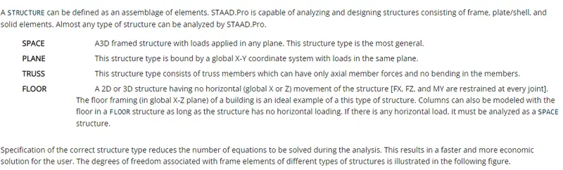
3. 1. Name the structure systems in STAAD Pro? Explain each system?
2. Explain the coordinate system adopted in STAAD Pro software.
3. Elaborate DBR and its uses.
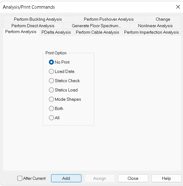
4. Explain the different types of analysis options in STAAD pro.
5. Explain the difference between Fixed and Fixed But condition.
Practical
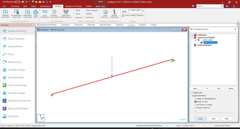
1. Create a STAAD Model with the following Specification
a. A beam of span 16m
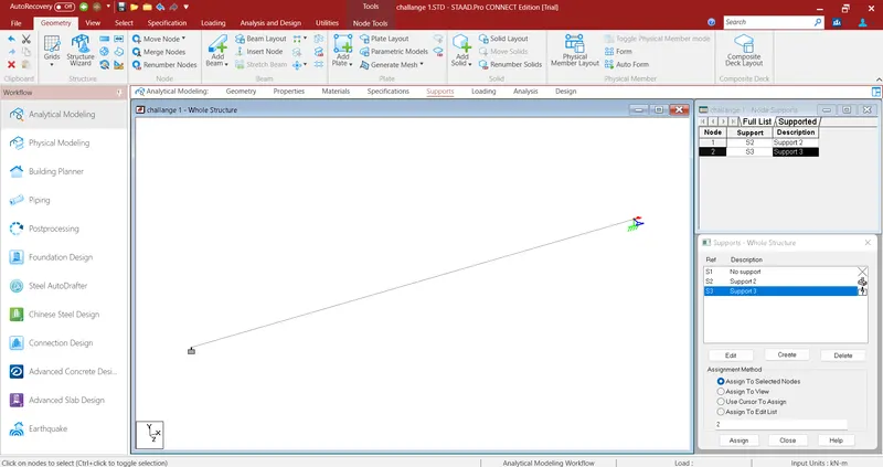
b. Support : Fixed on one end and Roller support(Horizontal) on the other end
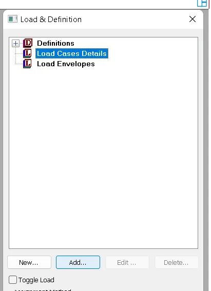
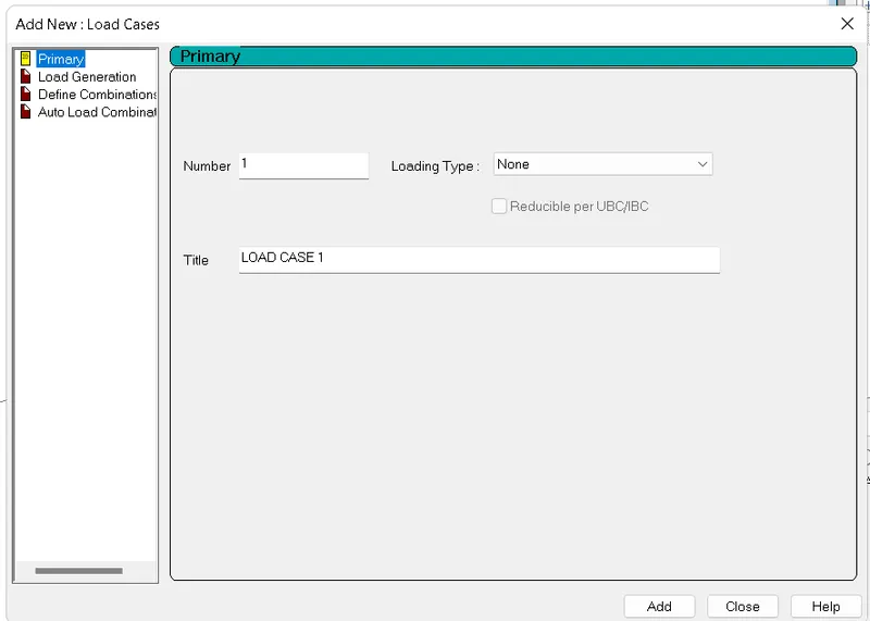
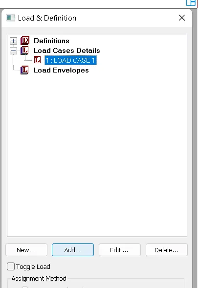
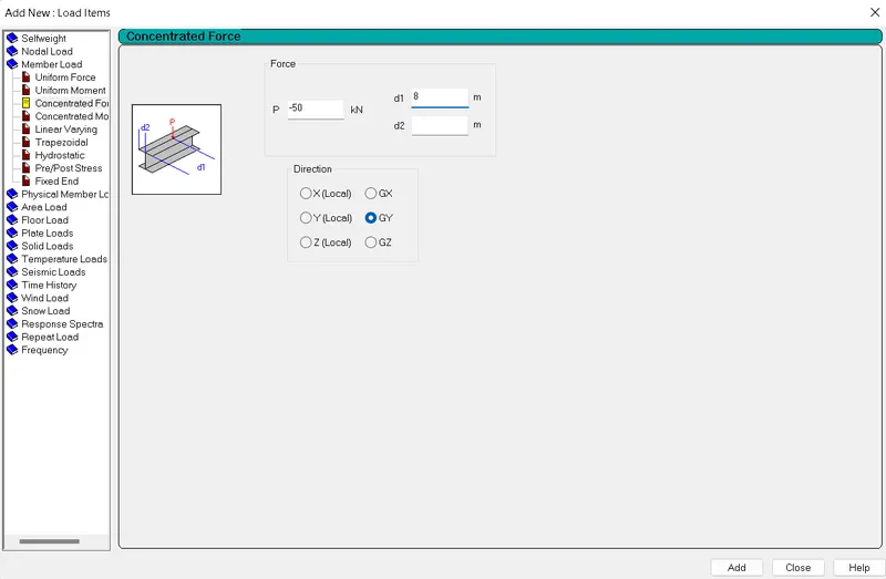
c. A point load of 50 kN at the mid-point
d. Draw SFD and BMD using software
ANSWER:-
1.)
1
- Select STAAD Import from the backstage.The Import from STAAD.Pro dialog opens.
- Click [...] in General settings to browse and select a STAAD.Pro (*.std) file to import.
- Select Use Mapping File in Section Mapping settings, and then click [...] to browse and select a mapping file to import.
Note: Mapping files are delivered with AECOsim Building Designer, and are named using analysis program names. Their function is to compare two lists of section data, and to map the STAAD.Pro sections to the corresponding sections in AECOsim Building Designer. They are located in the active configuration \\Configuration\Datasets\[active dataset]\Datadata folder
- Set the catalog type and catalog instance assignments for the imported member types. This data is used by AECOsim Building Designer to rebuild the members' structural data as defined in the structural member catalogs.
- In Steel settings, select a section definition that is to be designated as the Default Section Name. This section definition is applied to imported members whose section data is not available in AECOsim Building Designer.
- Check Verify to scan the imported file for unknown sections.
The Unknown Sections dialog appears providing an opportunity to write the unknown sections to the active XML section definition file before importing.
- In Revision Tracking, check Use Design History. Design History tracks changes to a DGN file. Viewing details about the revision by using the controls on this tool.
- Click Import.
The update design dialogue appears. Review detailed information about each imported member and select which ones you want to import before accepting them into the target DGN file.
Note: Update Design Results contains Load Case and Load Combination data imported from the STAAD.Pro (*.std) file. - Click Update to complete the import process.
The structure is updated.
- concret
- aluminium
- steel
- and stainless steel.
- Open Structure Wizard and start creating new project
- Open building planner mode and start creating Project
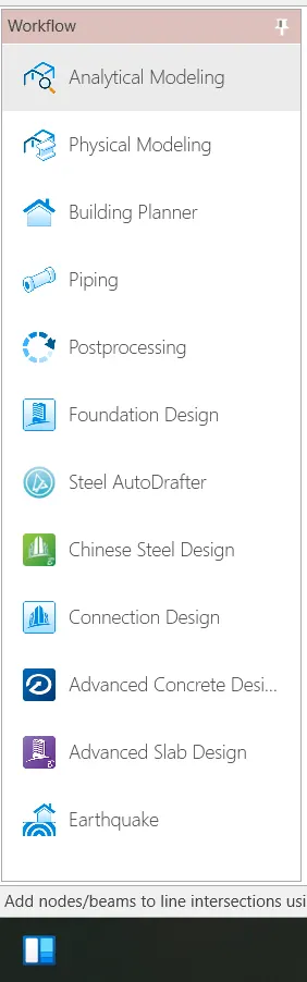
- GO to the analytical Model
- Go to properties

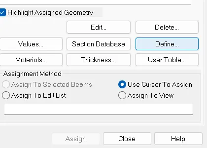
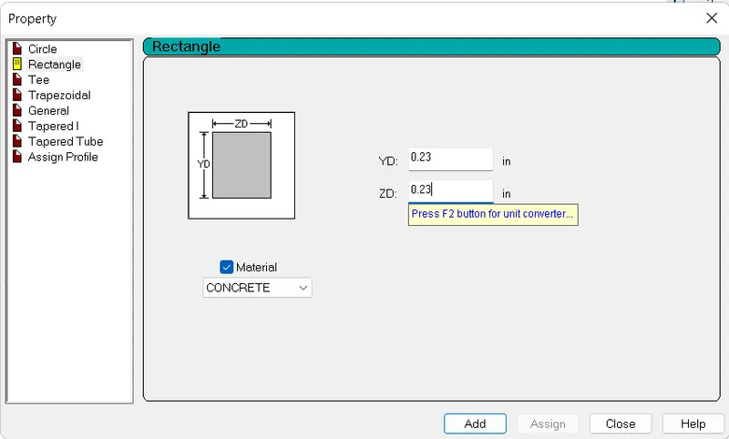
- Go to define and Add properties
- Section code book.
- Grade of concrete .
- Grade of Steel.
- Maximum Size of Reinforcement.
- Minimum Size of Reinforcement.
- Number of bars.
- Node Cursor.
- Beam Cursor.
- plate Cursor.
- Solid Cursor.
- Geometry Cursor.
- Member Cursor.
- Plate and Solid Cursor.
- Load Cursor.
- You need to prepare the geometry tab.
- Then specify the properties tab.
- Then assign the materials tab.
- Run Design Tab.
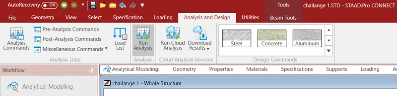
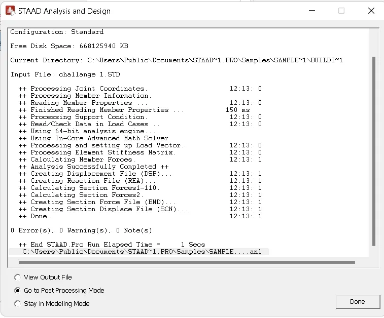
- Assign specifications tab and run analysis.
- Introduction.
- Design Code.
- Materilas For Sub Structure And Super Structure.
- Cover of Reinforcement.
- Loads.
- Design reports.
- After analysis a structure has to be designed to carry loads acting on it considering a certain factor of safety.
- In India structures are designed by using various Indian codes for both concrete and steel structures.
- The design in STAAD.Pro supports over 70 international codes and over 20 U.S. codes in 7 languages.
- After designing the structure it is again analyzed and results of analysis for each beam and column is shown in the output file
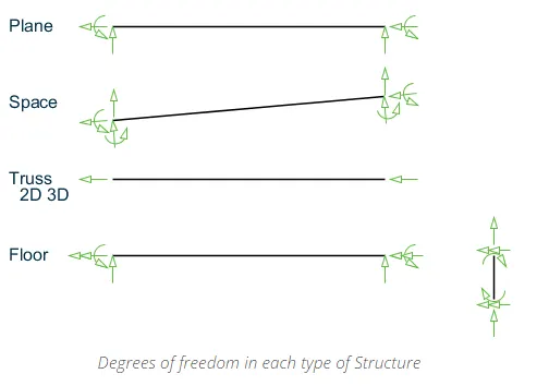
- Global coordinate system
- Local coordinate system
Conventional Cartesian Coordinate System - This coordinate system is a rectangular coordinate system (X, Y, Z) which follows the orthogonal right hand rule. This coordinate system may be used to define the joint locations and loading directions.
Cylindrical Coordinate System - In this coordinate system, the X and Y coordinates of the conventional Cartesian system are replaced by R (radius) and 9 (angle in degrees). The Z coordinate is identical to the Z coordinate of the Cartesian system and its positive direction is determined by the right hand rule
Reverse Cylindrical Coordinate System - This is a cylindrical type coordinate system where the R- O plane corresponds to the X-Z plane of the Cartesian system. The right hand rule is followed to determine the positive direction of the Y axis.
Local coordinate system - A Local coordinate system is associated with each member or element) and is utilized in MEMBER END FORCE output or local load specification. Each axis of the local orthogonal coordinate system Is also based on the right hand rule. Note that the local coordinate system is always rectangular. A wide range of cross-sectional shapes may be specified for analysis. These include rolled steel shapes, user specified prismatic shapes etc..
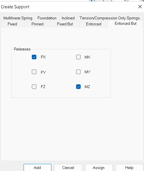
When the ENFORCED or ENFORCED BUT type of support is specified, for those degrees of freedom which are to be treated as restrained, STAAD assigns a spring with a very high spring stiffness translational stiff springs for translational restraints, and rotational stiff springs for rotational restraints. Those degrees of freedom which are free to displace are assigned springs of zero stiffness. Hence, for all the 6 degrees of freedom at such supports, the displacements are calculated. The ones which have a stiff spring will end up having a negligible displacement, and those with zero-stiffness-springs will have a displacement based on the structure geometry, properties and loading.
- Even though the two types follow different approaches, the end result - joint displacements, member forces and support reactions - should be the same.
- Since the number of unknowns is less in the former method compared to the latter, the time required to compute the results will also be comparatively less using the first method. If the model is large, there may be a significant reduction in time required to perform the analysis.
- For supports directly attached to plates or solids, if the supports are subjected to artificial displacements (called sinking support or support settlements), the effects caused by such displacements can be computed only if the ENFORCED type of support is used. In STAAD, support displacement loads cannot be applied to such models when the FIXED type of support is specified.
- For the ENFORCED BUT type, there is no provision to specify a spring constant. The only choices, which are built into the program, are - zero stiffness or very high stiffness. So, if a user plans to assign his/her own spring constant, the FIXED BUT type is the only choice.
- If the engineer plans to analyze a model in which support conditions change depending on the loading condition (hence he/she specifies the support command multiple times in the model), there are a few restrictions on how the supports must be assigned. These are mentioned in Section 5.38 of the Technical Reference manual where the CHANGE command is described. The ENFORCED support may offer a way to overcome some of those restrictions.
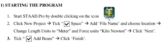
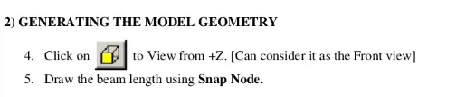
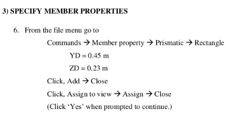
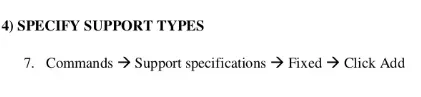
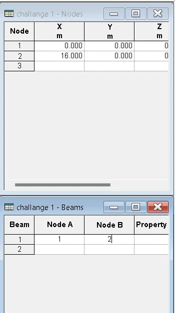
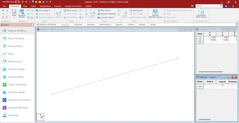
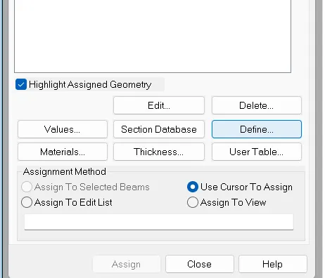
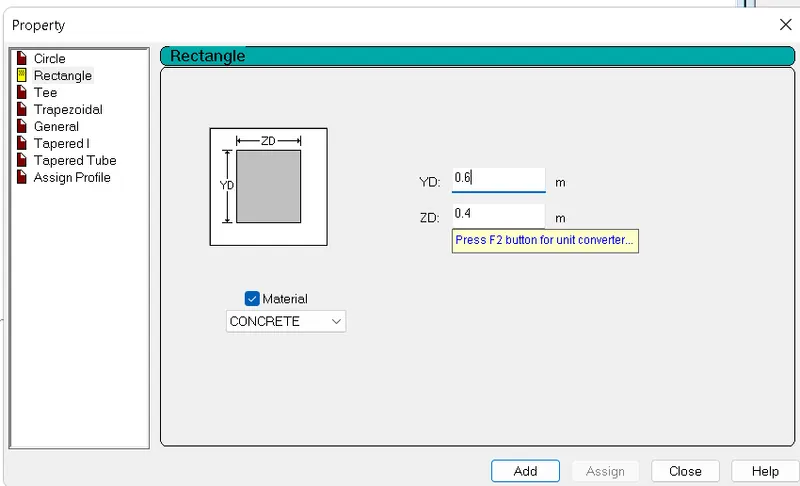
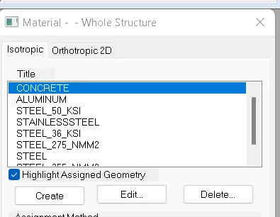
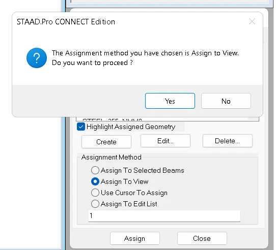
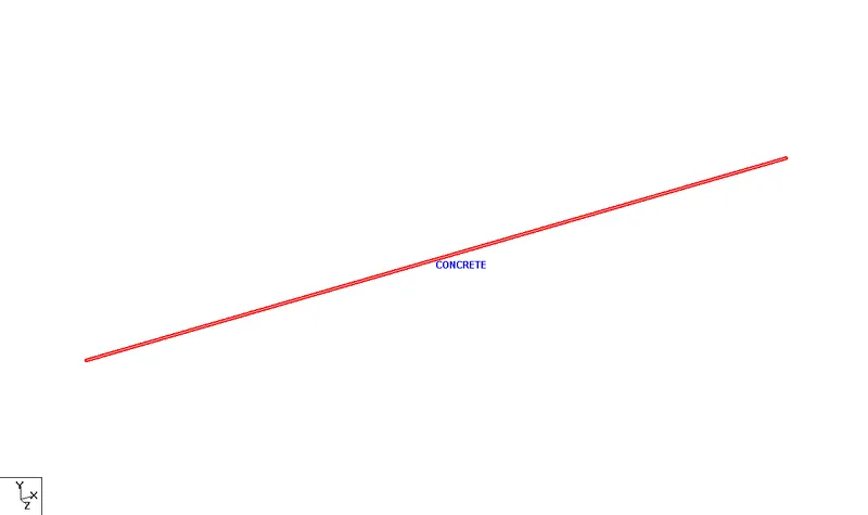
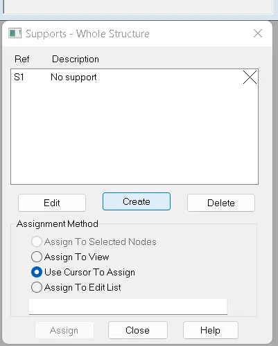
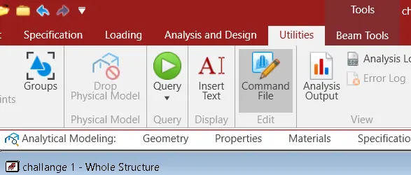
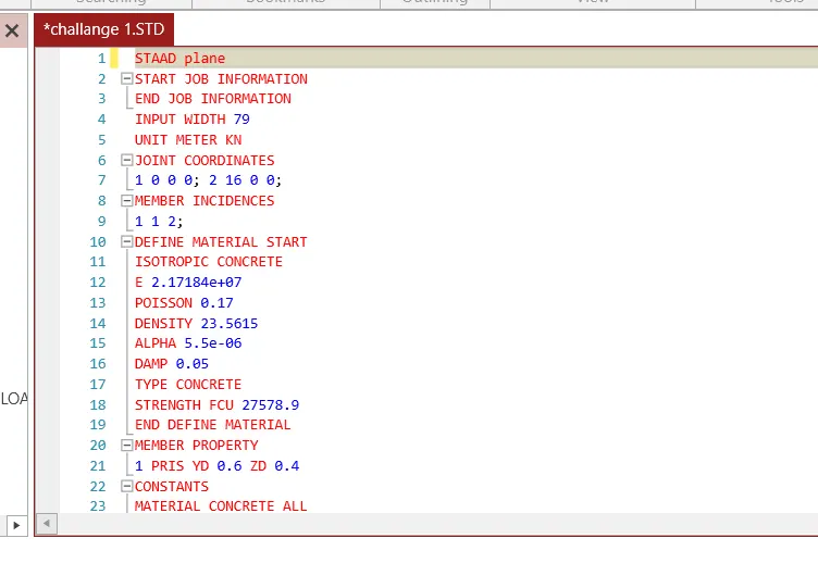
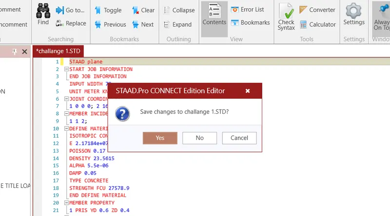
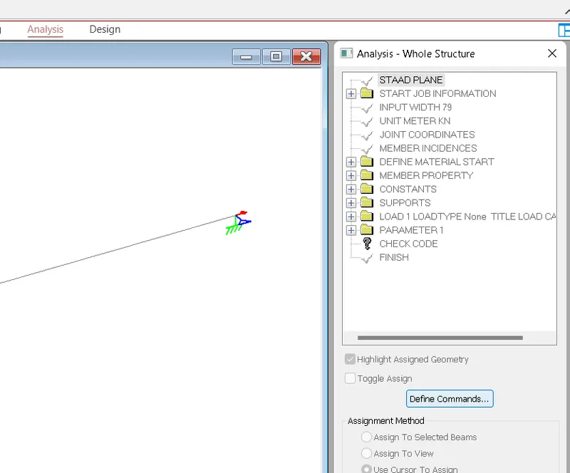
To create a STAAD PRO model following given procedure.
Procedure:-
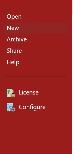
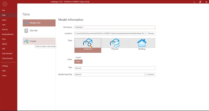
 .
.
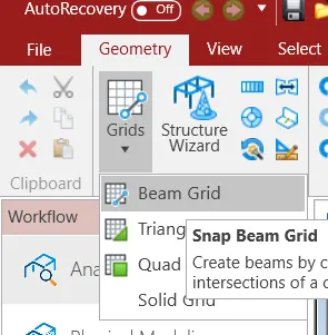




Conclusion:-
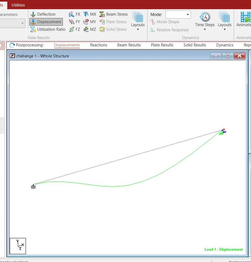
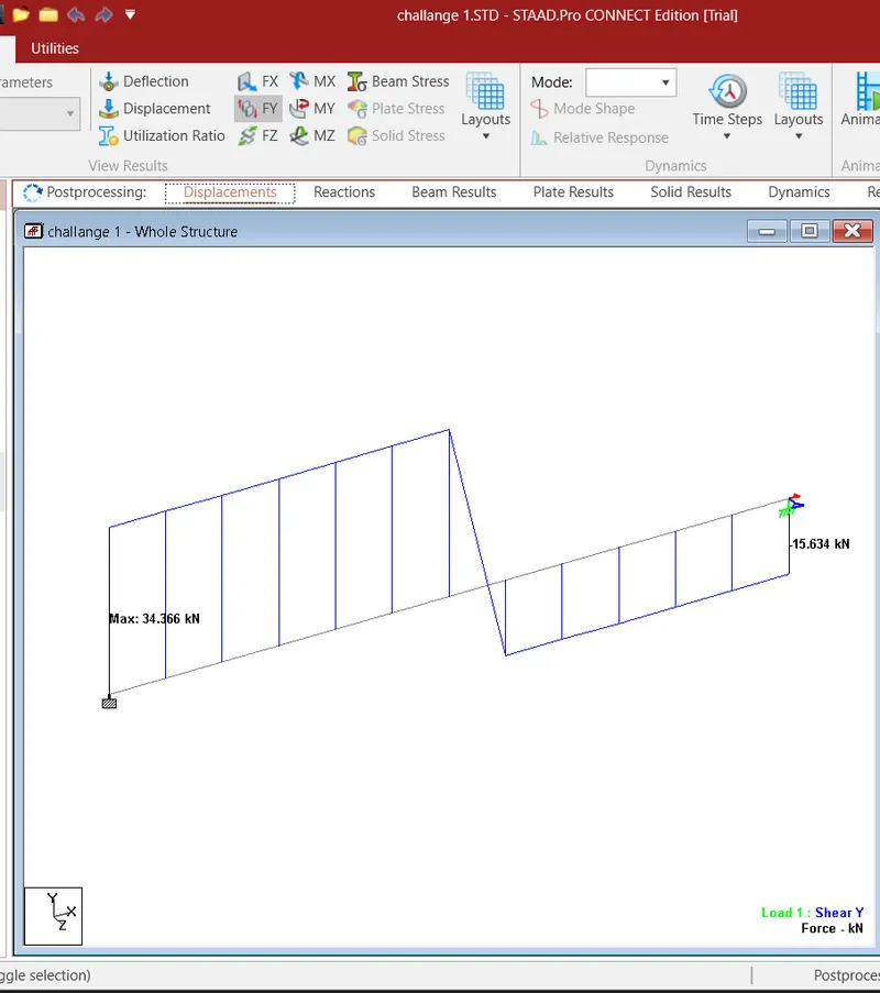
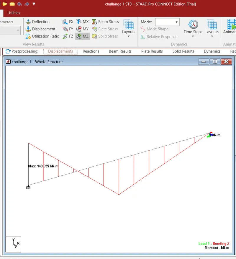
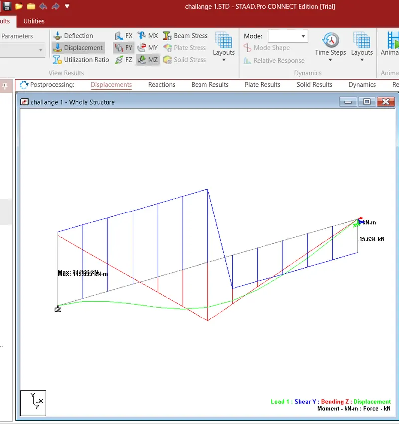
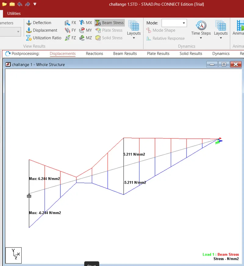
SFD and BMD of the above beam is shown.
Result:-
SFD and BMD of the above beam is shown.