Week 1 Challenge
Ans 1.1
. Select STAAD Import from the backstage.
The Import from STAAD.Pro dialog opens.
. Click [...] in General settings to browse and select a STAAD.Pro (*.std) file to import.
. Select Use Mapping File in Section Mapping settings, and then click [...] to browse and select a mapping file to import.
. Set the catalog type and catalog instance assignments for the imported member types. This data is used by AECOsim Building Designer to rebuild the members' structural data as defined in the structural member catalogs.
. In Steel settings, select a section definition that is to be designated as the Default Section Name. This section definition is applied to imported members whose section data is not available in AECOsim Building Designer.
. Check Verify to scan the imported file for unknown sections.
The Unknown Sections dialog appears providing an opportunity to write the unknown sections to the active XML section definition file before importing.
. In Revision Tracking, check Use Design History. Design History tracks changes to a DGN file. Viewing details about the revision by using the controls on this tool.
. Click Import.
The update design dialogue appears. Review detailed information about each imported member and select which ones you want to import before accepting them into the target DGN file.
. Note: Update Design Results contains Load Case and Load Combination data imported from the STAAD.Pro (*.std) file.
. Click Update to complete the import process.
The structure is updated.
Ans 1.2.
for that material just go to your staad pro software and create a new model and the you have a option called material that can be use in the design using staad pro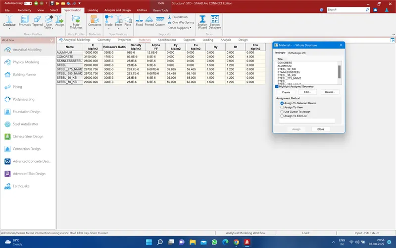
like concrete , aluminum, stainlesssteel, steel, etc
Ans 1.3.
YES
Ans 1.4.
Name of three way to creat a model called Analytical and physical and building 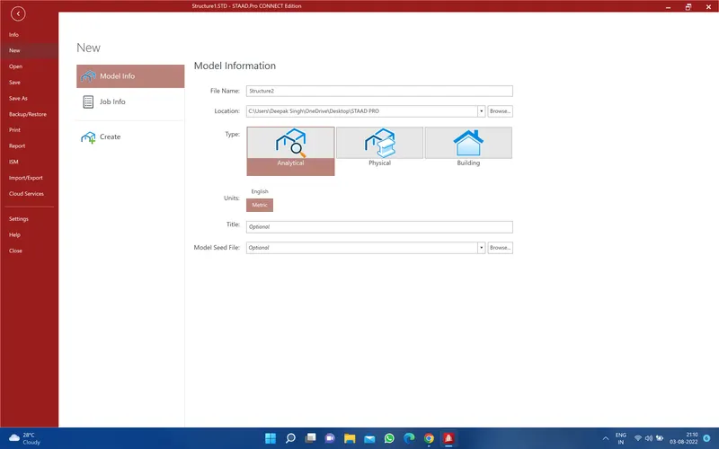
Ans 1.5.
The steps followed to assign properties in a model.
for that creating the Geometric model you have a option called property just click on it then open a window then you have option called define click on it then select the property and give the dimention and click on add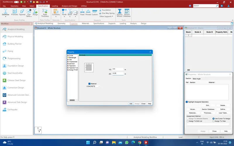
then go and select define material and click on the assign to view and assign it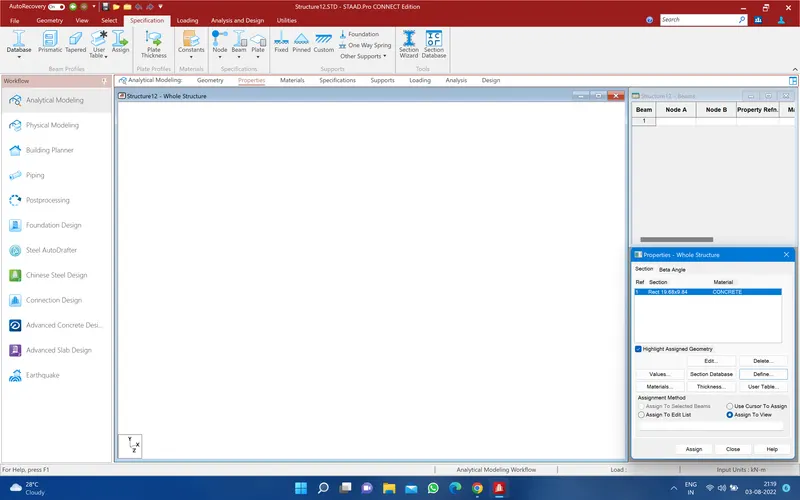
Ans 2.1.
Shear reinforcement, Behavior requirements , Design spectrom, Importance class for building, Development length for building, Grade types
Ans2.2
Nodes cursor, beam cursor, plate cursor, Solid cursor, Geometry cursor, member cursor, plate & soild cursor
Ans 2.3.
. You need to prepair to geometry tab.
. Then specified the property tab.
. Then assign the material tab.
. Run design tab.
. Assign specification tab and run analysis.
Ans 2.4.
1. start the staad pro by double click on the icon
then click the new project andd the fie name and select the location select the metric and creat
2. click on the view fron the +Z (can consider it as the front view)
draw the beam length using the snap Node
3. from the file menu go to memberproperty , parametic and Rectangle then click on add then close
then click on assign to view and assign and close
command , sport specificatio , fixed, click add
Ans2.5 after analysis a structure has to be designed to carred load acting on the considaring a certen factor of sefty
. in india structure are design by using various indial code for both concrete and steel sructure
.The design in staads pro support over 70 international code and over 20 us code in 7 language
. After design the structure it is again analyze and result of analysis for each beam and column is show in the output file
Ans 3.1.
A structure can be defined as an assemblage of element staads pro is capable of analysis and designing structure consisting of frame plate/shell and solide element . almos any type of structure can be analysis by staad pro
SPACE: A 3D frame structure with load apply in any plane. This structure is most general
PLANE: The structure type is bound by a global X-Y coordinate system with loads in same plane.
TRUSS: This structure type consists of truss member which can have only axial member forces and no banding in the member.
FLOORS: A 2D and 3D structure having no horizontal (global X or Z) movement of the structure [ FX, FZ and MY are resistrain at every joint ].
The floor framing (global X - Z) of a building is an ideal example of a this type of structure . column can also be modeled with the floor in a floor structure as long as the structure has no horizontal loading . if there any horizontal load , it must be analyze as a space structure
Ans 3.2.
STAAD use two types of coordinates system to define geometry and loading patterns.
1. GLOBAL coordinates system.
2. LOCAL coordinates system.
1. GLOBAL coordinates system.
The global coordinates system is an arbitrary coordinate system is space which is utilized to specifie the over all geometry & loading pattern of a structure
Conventional cartesian coordinates system .
This coordinate system is a rectangular coordinate system (X,Y,Z) which follow the arthogonal right hand rule. This coordinate system may be use to define the joint location and loading direction .
Cylindrical coordinate system .
In this coordinate system the X and Y coordinate of the Conventional cartesian coordinates systemare riplaced by R (radius) and `theta`(angle of degrees) the z coordinate identical to the Z coordinate of the cartesian system and its positive direction is determine by the right hand rule
Reverse Cylindrical coordinate system.
This is the cylindrical type coordinate system where the R- `theta`plan corrosponds to the x-z plane of the cartesian system. the right hand rule is followed to determine the positive direction of the Y axis
2. LOCAL coordinates system.
A local coordinate system is associated with each member (or element ) and is utilize in MEMBER END FORCE output or local load specification.
Each axis of the local orthogonal coordinate system is also based on the right hane rule. Note that the local coordinate system is always rectangular.
A wide range of cross- sectional shape may be specify for the analysis. These include rolled steel shape , user specified prismtic shape etc.
Ans 3.3.
DBR: DBR forms the base for any project that is the frist shape have to creat and will be discussing and generate a design basis report for sample project
Ans 3.4.
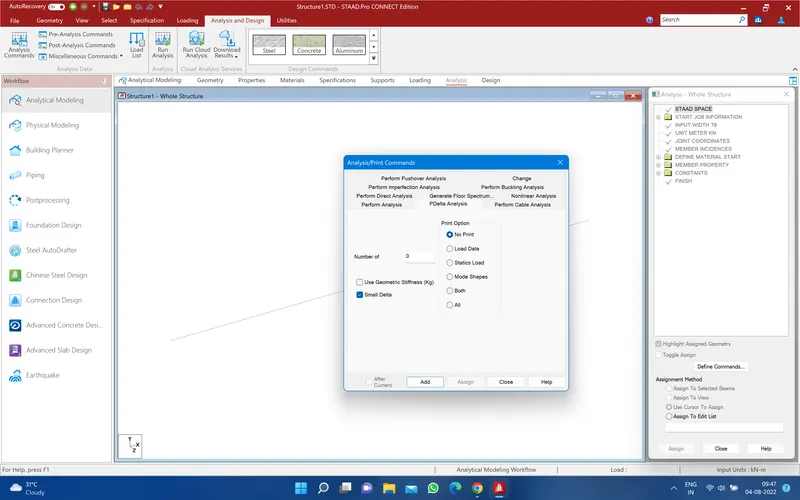
Nine types of analysis option in the staads pro
Perform Pushover analysis, Perform Impertection analysis, Perform Bucking analysis, Perform direction Analysis, Generate Floor specturm analysis , Non linear Analysis, Peerform Analysis, Pdelta Analysis, Perform cable Analysis
Ans 3.5.
Fixed support- If is support where in all the translational movement and a rotationl movement Restraint as you see in fig.
all these FX, FY, FZ, MX, MY, MZ are restraint it is not going to change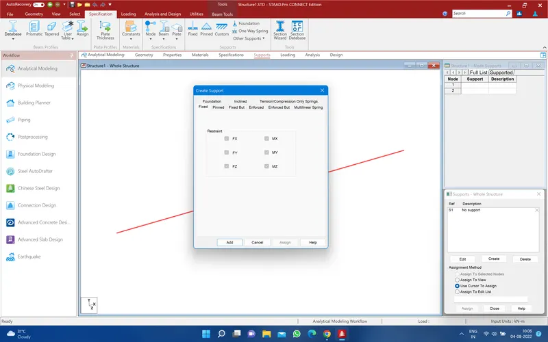
fixed But support- If you want to creat a roller support just go to Gixed But Support
Ex: MY Roller is in the horizontal Roller support I have to Relesed my FX and MZ and I leave all other as such and I can creat roller support
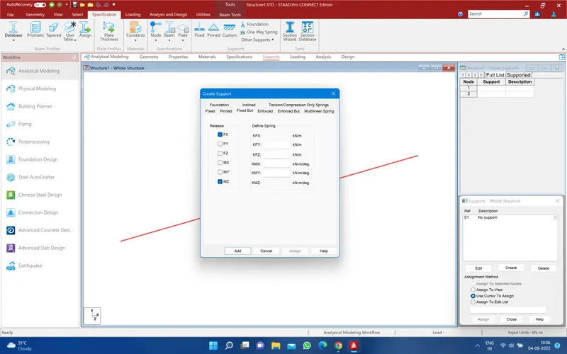
Practical : To creat a staad pro model following given procedure
frist just go and open yoyr software then creat a new model give the file name select the matric and creat 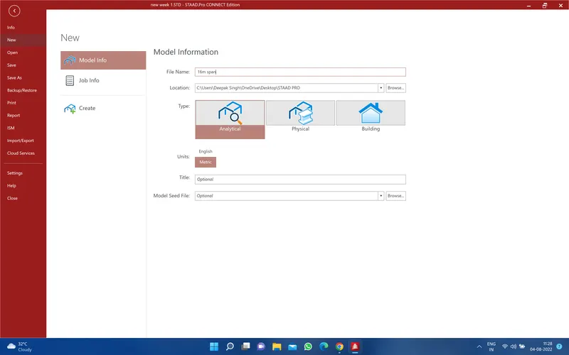
Then go to grie and select the beam grid then ctreat the 16 m span as in the question
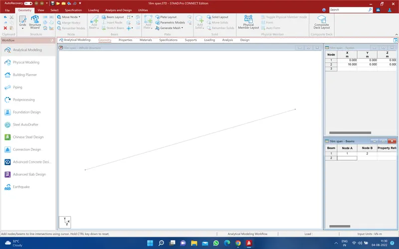
Then go to property and define the property 250mmx500mm column rectangle 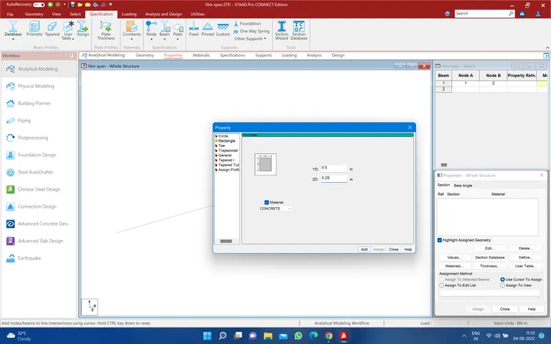
then add and close then assign the property 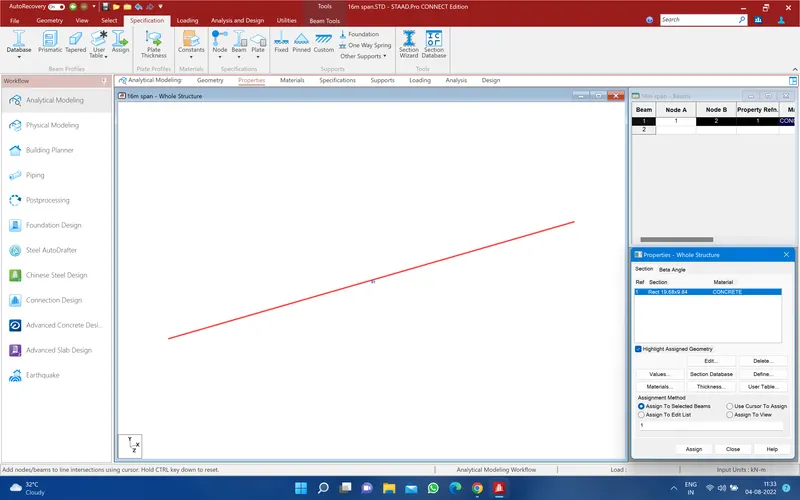
Then go to material assign select the concrete and assign to view 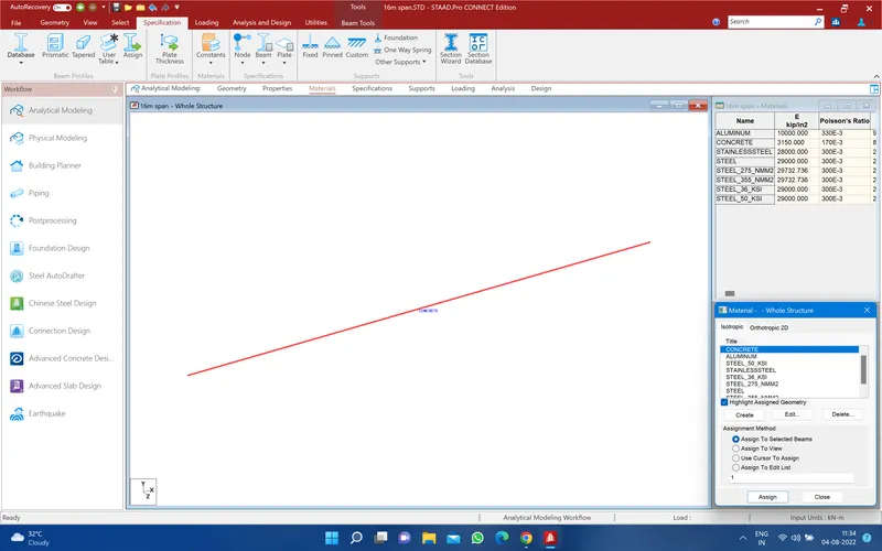
Then go to suppore and creat the support fixed and roller support (Enforcebut) and assign it 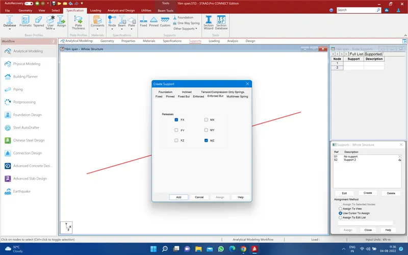
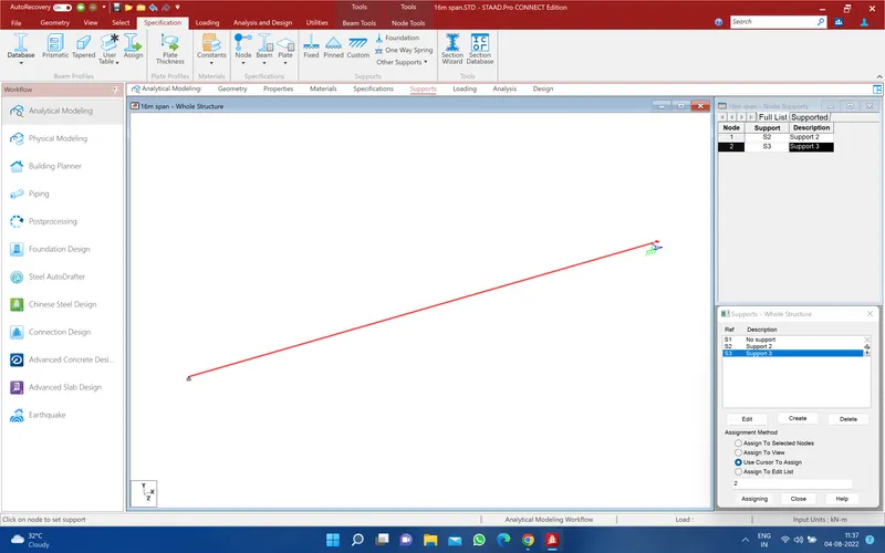
THEN go to load and and add the load case and add the DL 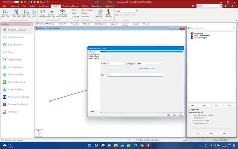
then select the DL and add the load type then go to and selevt the concentrated load and apply -50KN load global y direction and specify the point where act the load 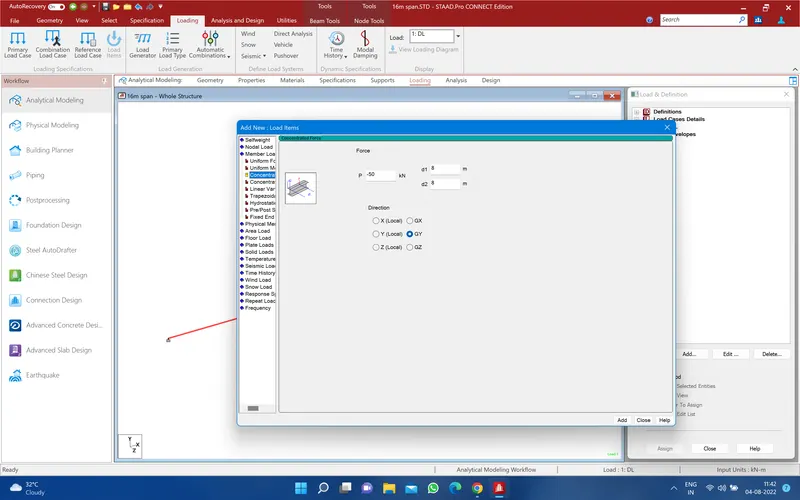
then select the load and assign to view and and assign it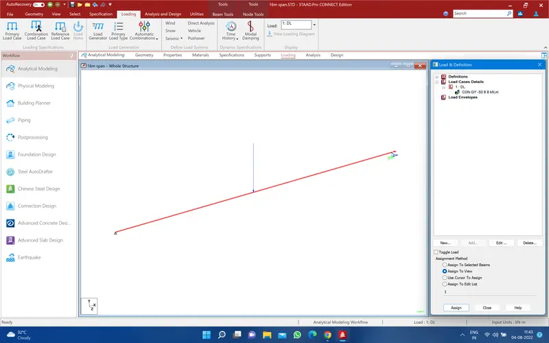
then go to utilize and command file and save and change space to palne 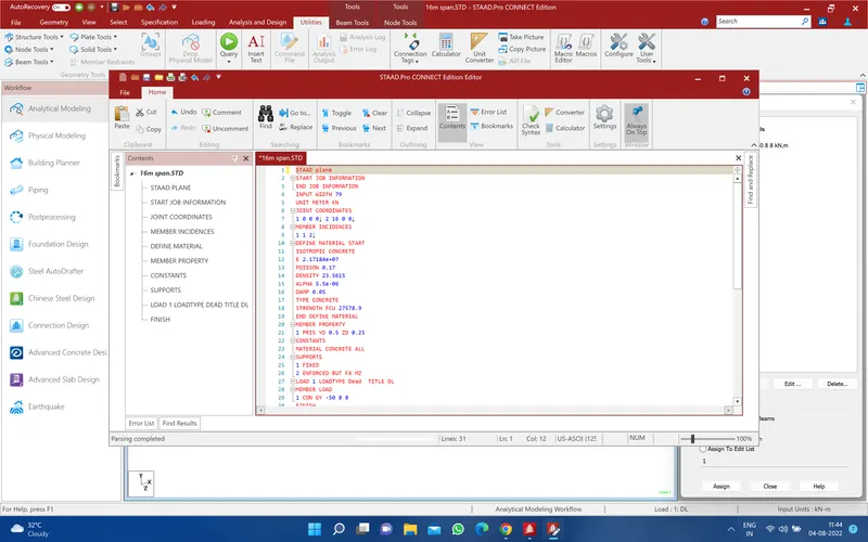
then go to analysis command and add then run analysis
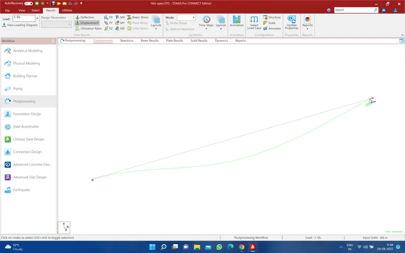
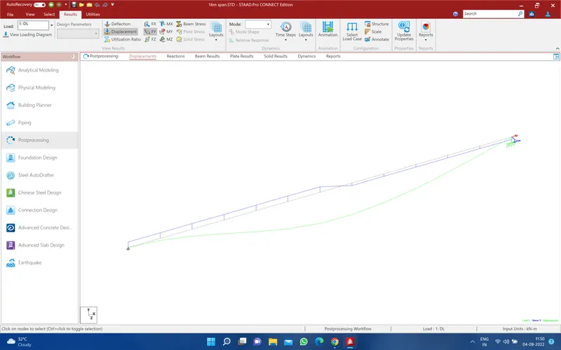
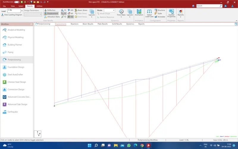
SFD AND BMD AND DISPLACEMENT