Tool Test two for HYPERMESH
AIM :
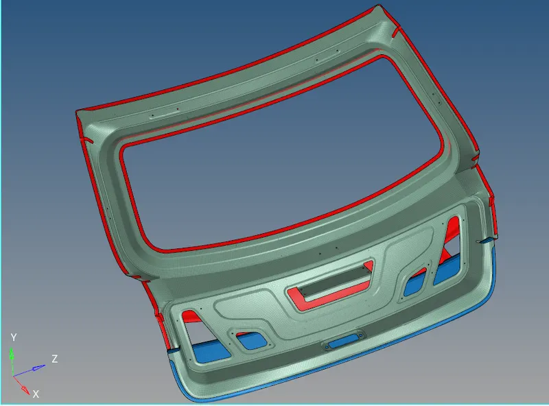
To creating a manual midsurface from given back door component, preprocessing on it and all created elements should be passed the given element parameters.
OBJECTIVES :
1) Extracting a manual midsurface from parent component.
2) Geometry cleanup on a midsurface as per convenience for meshing.
3) To Checking the element qualities as per given element criteria.
CAD MODEL :
1) Open a Hyperworks software and set the user profile which depends on components gets deformation. If a deformation is small, we gonna to perform a "Optistruct" user profile which is implicit solver and if a deformation is large, we gonna to perform a "RADIOSS" user profile which is explicit solver.
2) Click the "Import Solver Deck" option from where tool bar section, then select the "Import Gemetry" option and select the file type which is "IGES" because our given model file type is 'iges'. Click the folder option and select the respective file which will going to perform and then click the "Import option" it showing up the components from graphical window.
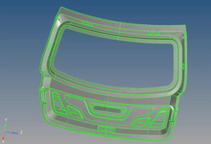
3) After importing the model, by default "Auto" geometry color mode had selected. For visualizing the topologies, manually change into "By Topo" mode for viewing the "Free edges, Sharped edges, T Junction edge and Supressed edge" from components.
4) Make sure delete the solids from imported model by using delete option. In this model, there's no any solid parts are present.
5) In this file have around 200 components, but necessary components are only one component which have inner, lower and then upper part. We have to use this single component to extracting the middle surface in separately for upper, lower and inner body mid surface.
6) Remaining unwanted or unassociated components have been deleted by just selecting the components and delete it.
PROCEDURE FOR ATTAINING OBJECTIVES :
i)Extracting a Manual Midsurface :
1) Create a new collectors to which is used to save the respective middle surfaces for inner, upper and lower parts.
2) Measure the thickness of the respective body component by using "Two points" option under the distance panel or directly press the "F4" button from the keyboard.
3) For extracting the manual middle surface, go to "Surface Edit" panel under where "Geometry" main menu panel. Selecting one of the surface from where parent component regrading to respective body, by using "by face" option to select the entire body face surface.
4) Press shift button from the keyboard, with that press the right button from the mouse and drag it out to unselect the half a surface from the preselected surface. Because, given back door model is exactly in symmetrically in shape and this way helps us to reducing the geometry cleanup timing.
5) Make sure create a new collectors which is used to storing the mid surfaces for inner body, upper body and lower body individually when we perform a offsetting.
6) A middle surface is created between the two surfaces which is created at where half a thickness distance of parent component thickness.
7) Execute into offset option to create a middle surface on that particular component, make sure check the vector direction of offset surface before execute into the offset.
I) Inner Body :
1) Set the current component which is "Mid surface for inner body" from the tab bar.
2) Put the offset distance value is 0.30 mm which is half a distance of parent inner component thickness. To select the face surface from where top of the inner body and unselect the half a surface from selected surface.
3) Make a duplicate surface to storing the current component and Execute the offset option to create a middle surface between the inner body thickness.
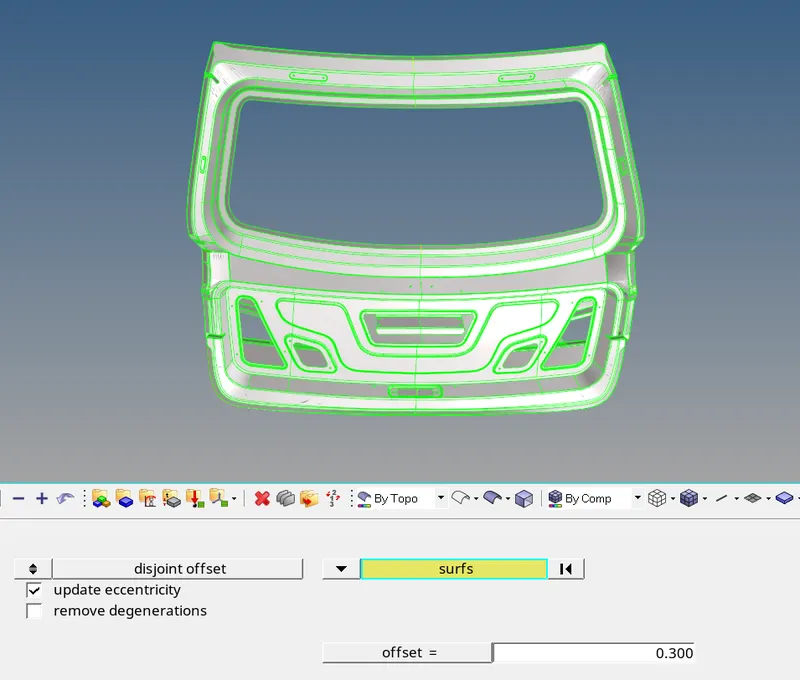
4) A component is exactly at symmetrical in shape about the Y axis. So, we create the mid surface any one of the either side and it will reducing the geometry cleanup timing if incase any error.
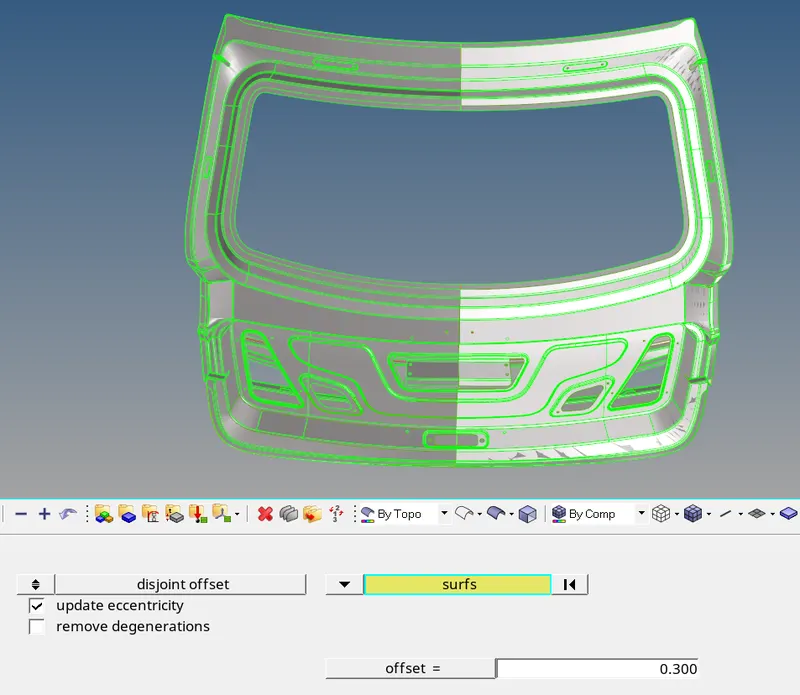
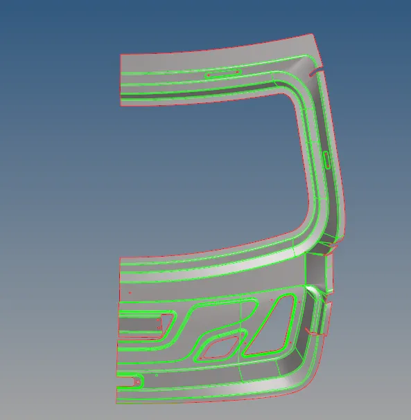
5) Unselect the all component except current component. Below image shows a mid surface for inner body.
II) Upper Body :
1) Set the current component which is "Mid surface for Upper body" from the tab bar.
2) Put the offset distance value is 0.375 mm which is half a distance of parent upper component thickness. The select the face surface from where top of the upper body and unselect the half a surface from selected surface.
3) Make a duplicate surface to storing the current component and Execute the offset option to create a middle surface between the upper body thickness.
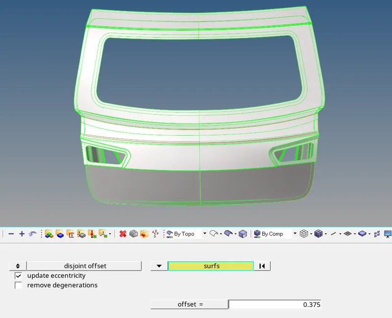
4) A component is exactly at symmetrical in shape about the Y axis. So, we create the mid surface any one of the either side and it will reducing the geometry cleanup timing if incase any error.
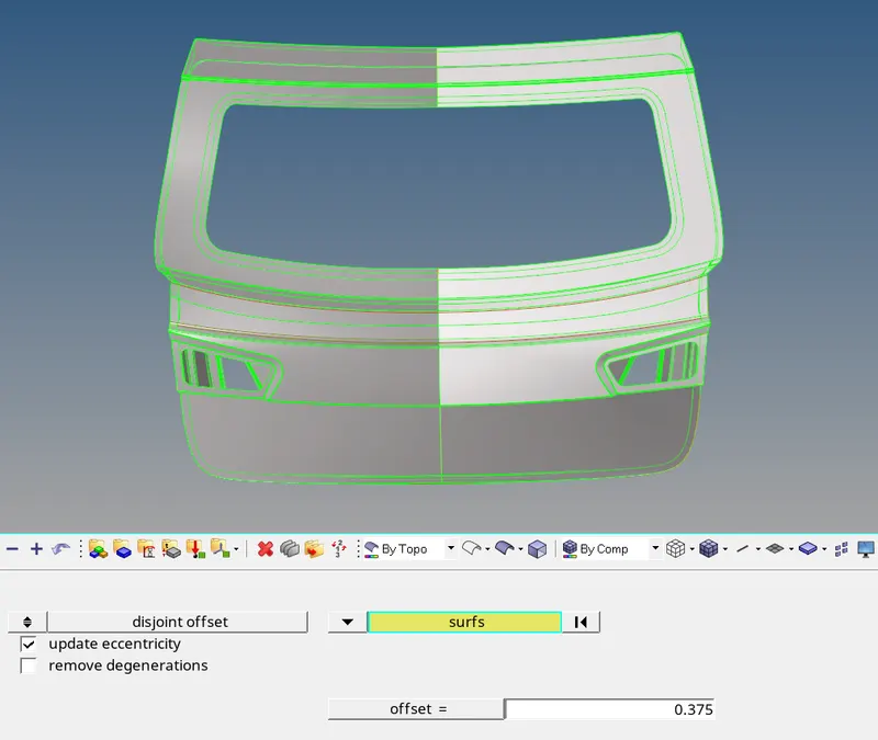
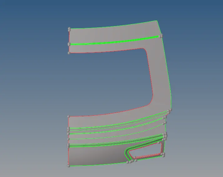
5) Unselect the all component surface except current component. Below image shows a mid surface for upper body.
III) Lower Body :
1) Set the current component which is "Mid surface for inner body" from the tab bar.
2) Put the offset distance value is 0.376 mm which is half a distance of parent lower component thickness. The select the face surface from where top of the lower body and unselect the half a surface from selected surface.
3) Make a duplicate surface to storing the current component and Execute the offset option to create a middle surface between the lower body thickness.
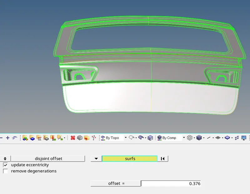
4) A component is exactly at symmetrical in shape about the Y axis. So, we create the mid surface any one of the either side, because it will reducing the geometry cleanup timing if incase any error.
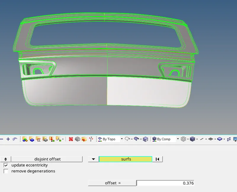
5) Unselect the all component except current component. Below image shows a mid surface for lower body.
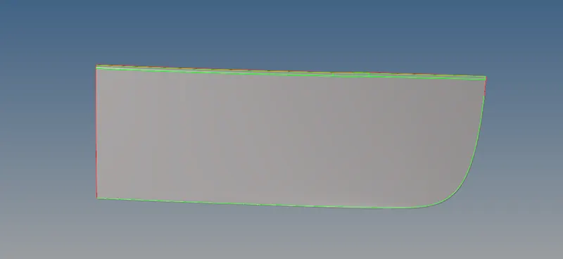
ii) Geometry cleanup on midsurfaces :
I) Inner body :
1) After extracting the mid surface, it seems some geometry issue happens. Inorder to resolve those errors, we need to cleanup the geometry in manually. In this case, we use the toogle option with higher tolerance value to rectify that error or else delete the error surface and then create a new surface on it.
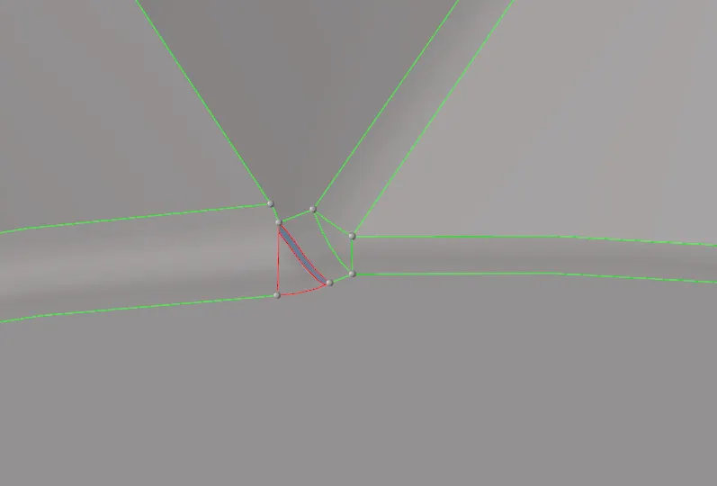
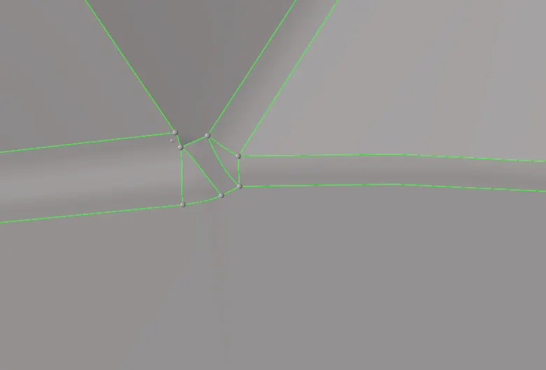
2) Similarly for this areas also to need a geometry cleanup, by using toggle, add/remove points and also surf split line or node option.
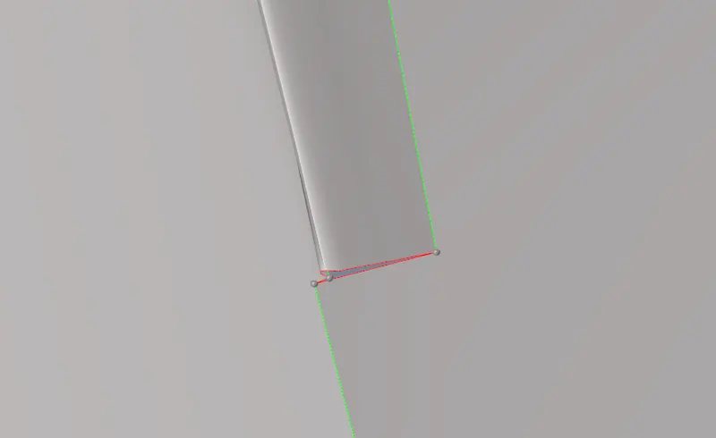
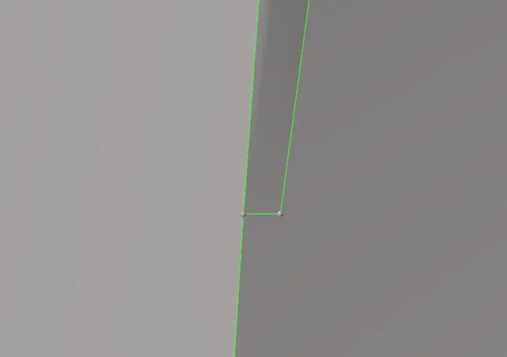
3) If two neighbour lines distance were below 3mm, it's necessary to supressing anyone of the line because it failing due to minimum element length criteria.
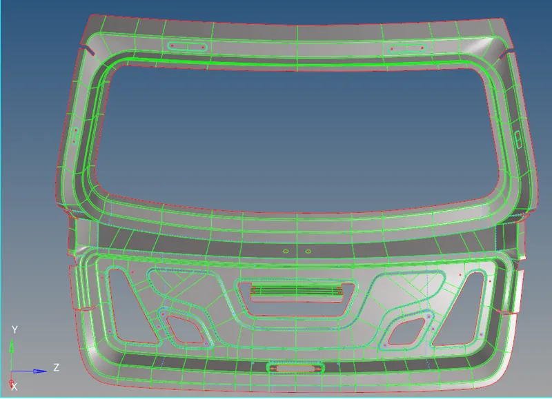
4) Additionally, to create a new sharped edge line, if a surface has converge or diverge area. If creating a more lines, mesh capturing very properly and neatly. After cleanuping, inner component looks like an below image.
II) Upper Body :
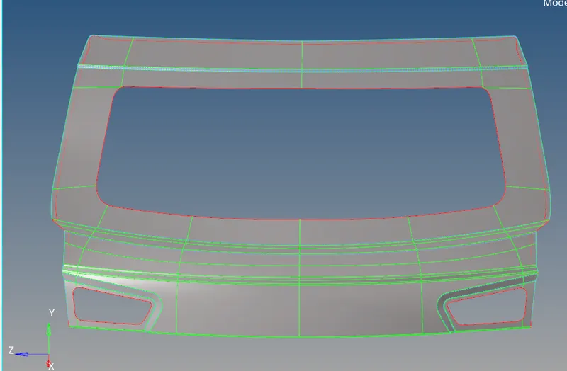
1) After extracting the midsurface, we need to create a new sharped edge lines and also supressing some lines for capturing a proper flow mesh. If a two line points lateral distance is falling under minimum element length criteria we should go to supressing any one of the line.
2) Also supressing the corner edge lines and create a new mid lines for capturing the mesh at where hemming portion.
3) After cleanup the geometry, a component looks like below snap.
III) Lower Body :
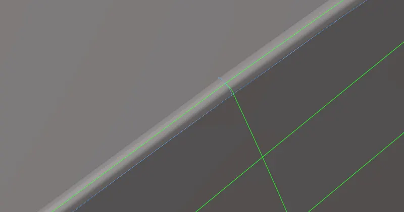
1) Supressing the two corner lines and create a new lines at where hemming surface for capturing the proper mesh flow and also restrict to element failing due to minimum element criteria.
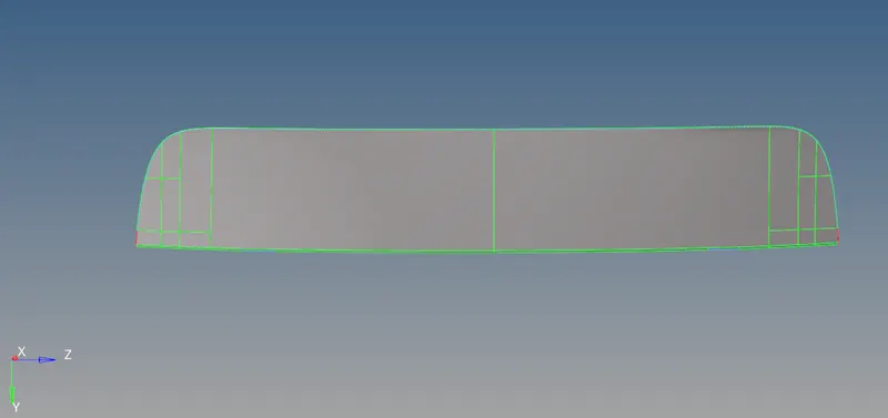
2) Choose anyone of the side from lower body component, create a sharped edge lines between the surface for capturing the better mesh flow.
iii) Generating the mesh :
1) To subdividing the respective component with infinitesimal control volume, that framework is called meshing. This process is called discritization.
2) Click "Auto mesh" panel under the "2D" main menu panel, change into surface selection mode instead of element selection mode. Select the surface and perform meshing operation on it, Repetitively to do the meshing operation whenever gets the proper flow mesh.
I) Meshing for Inner Component :
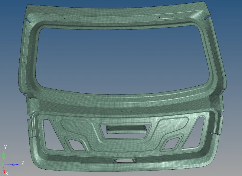
1) Before going to perform an meshing operation, make sure set the current component as "Middle surface for inner body". A inner body is exactly at symmetrical in shape, so perform meshing operation only on either half of a portion and then reflected into another side.
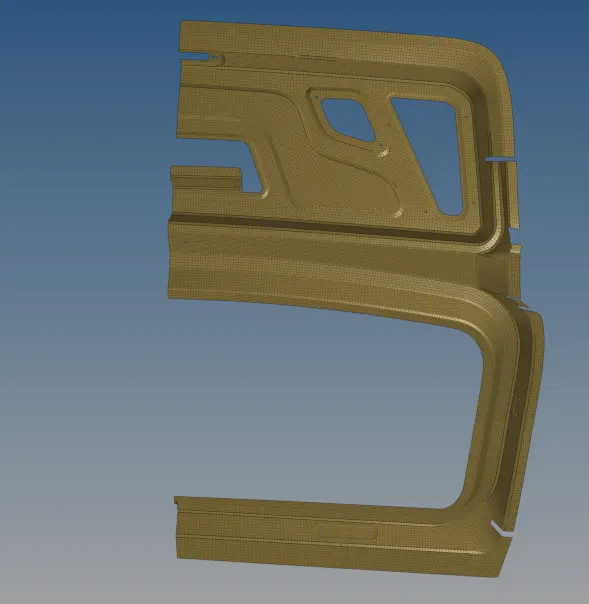
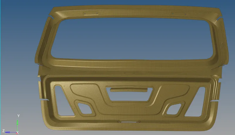
2) After completion of meshing operation on right half of a portion then reflecting the meshed element from right side to left side by using "Reflect" Option.
3) After reflection, a element have not any equivalence between the middle line or symmetrical line.
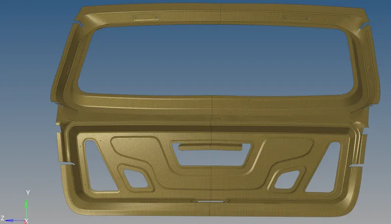
4) Inorder to resolving those non equivalence region, go to "Edges" panel under the "Tools" main menu panel. Select the respective component or near elements and click the "Equivalence" option to make connectivity between the elements with nodes.
5) After completion of reflection and equivalence process, a mesh elements will look like below image.
II) Meshing the Upper Component :
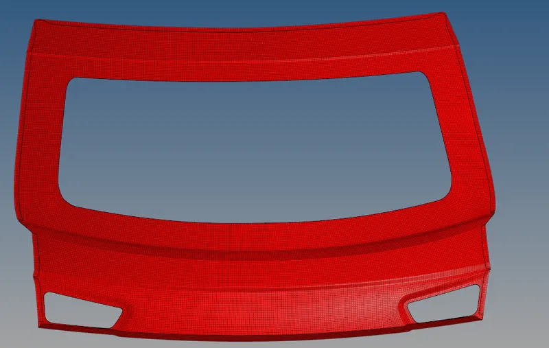
1) Disselect the all component except upper body surface and Set the current component for perform meshing operation.
2) Perform meshing operation on a surfaces untill complete the half a portion.
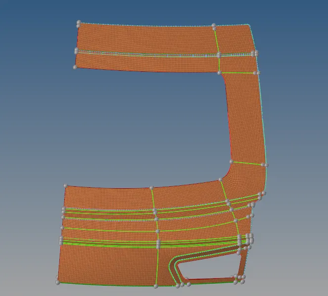
3) This component is exactly at symmetrical in shape, so it's simply reflecting the element into another side by using just "reflect" option.
4) After reflection process, a free edge lines are created due to unequivalence of the elements. Select the elements which are presented by near the free edge line to proceeding equivalence with nodes.
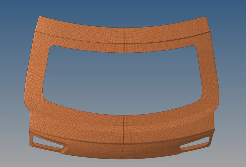
5) After reflection and equivalence process, a meshed elements are showing like below snap.
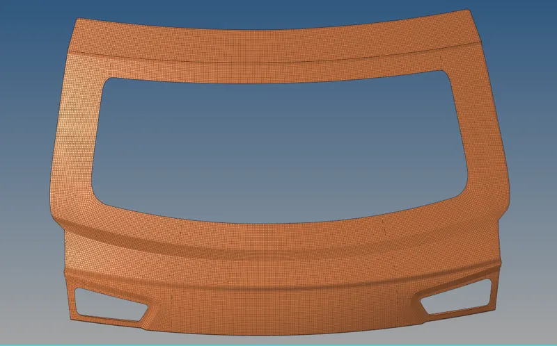
III) Meshing for Lower Component :
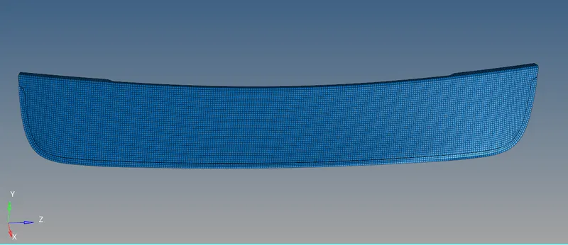
1) Disselect the all component except lower body surface and set the current component for perform an meshing operation on a surface.
2) Perform meshing operation on a surfaces untill complete the half a portion.
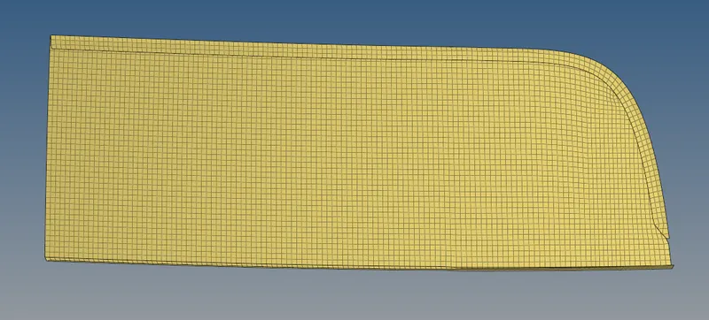
3) After completes the first half, then gonna reflect the meshed elements to another side by using "Reflect" option. Make sure create a duplicate elements to current component and then reflecting it.
4) After Reflection, a non equivalence elements were created. Inorder to resolve those, go to edges option and select the element which are near by unequivalence region and then click to equivalence with nodes.
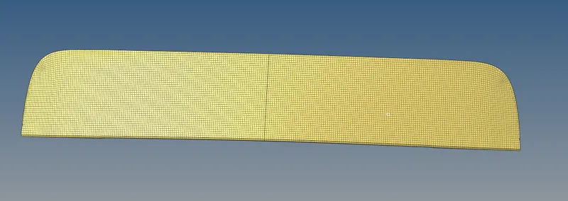
5) After reflection and equivalence process, a meshed elements are showing like below snap.
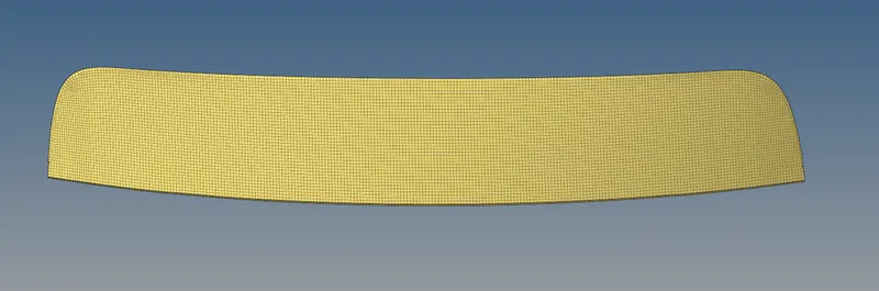
iv) Quality Checking :
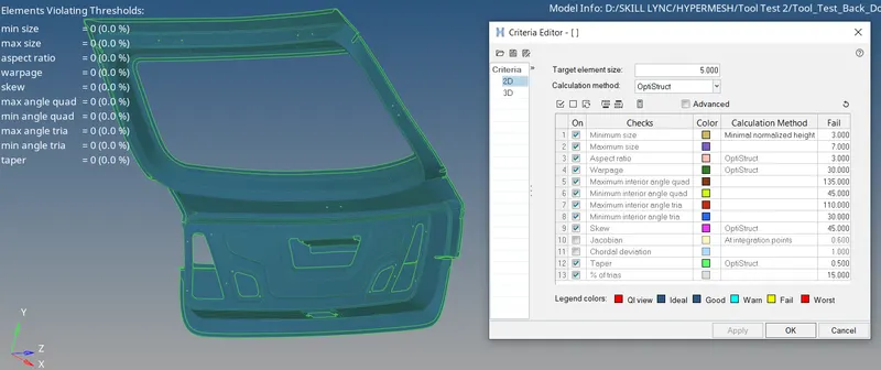
1) Before perform anything, make sure assigning the element parameters by using "Criteria Editor" through which "Preferences and criteria file settings". A Quality checking will help us to viewing the elements which are good or bad.
2) If the created elements are not satisfied the given element parameters, it would be bad and we will work on it ,untill a elements will satisfying the given criteria.
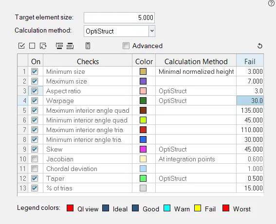
Inner Body :
A inner body element qualities are satisfied the all element quality parameters.
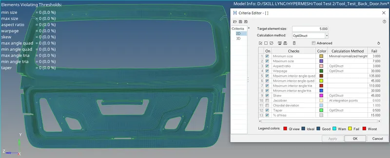
Upper Body :
A Upper body element qualities are satisfied the all element quality parameters.
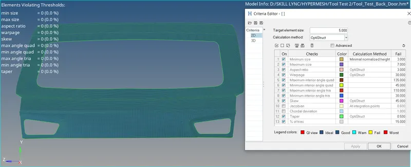
Lower Body :
A Lower body element qualities are satisfied the all element quality parameters.
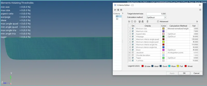
Back Door components :
All components element qualities are satisfied the given element parameters.
CONCLUSION :
Successfully completed the process of extract mid surface, geometry cleanup on a mid surface and then check the element quality with different element parameters on given back door body.
Inner component :
Upper Component :
Lower Component :
All Components :