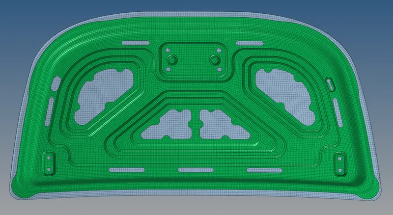
Tool Test one for Hypermesh
AIM :
To Preprocessing of given hood body and checking the mesh quality with different quality parameters, all should be done in Hypermesh software.
OBJECTIVES:
1) Cleanup the geometry before extracting the middle surface if it's required.
2) Extracting a middle surface from hood body in both inner and outer component.
3) Cleanup the geometry after extracting the middle surface in both hood inner and outer component, it should done in manually.
4) Generating the mesh on a middle surface with all elements are satisfying as per given element quality criteria.
CAD MODEL IMAGE :
1) Open a Hyperworks software then clicking the "Import Solver Deck" Option from where menu bar. Afterthat choose the file type which is "IGES" format, because a given file type is "iges" and then select the appropriate file which will be perform and then click "Import" option. After importing the file, a model has showing from graphical window.
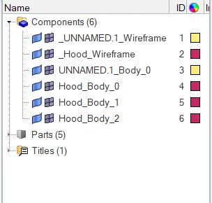
2) After importing into Hyperworks, we have six components are showing from the "Tab bar". We want to renaming the each component as per our convenience.
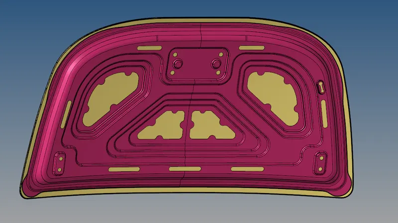
3) Somes of the few surface were associated with inside the Hood inner component, we don't need that surface in this case. So, we manually removing that surface at the stage of geometry cleanup.
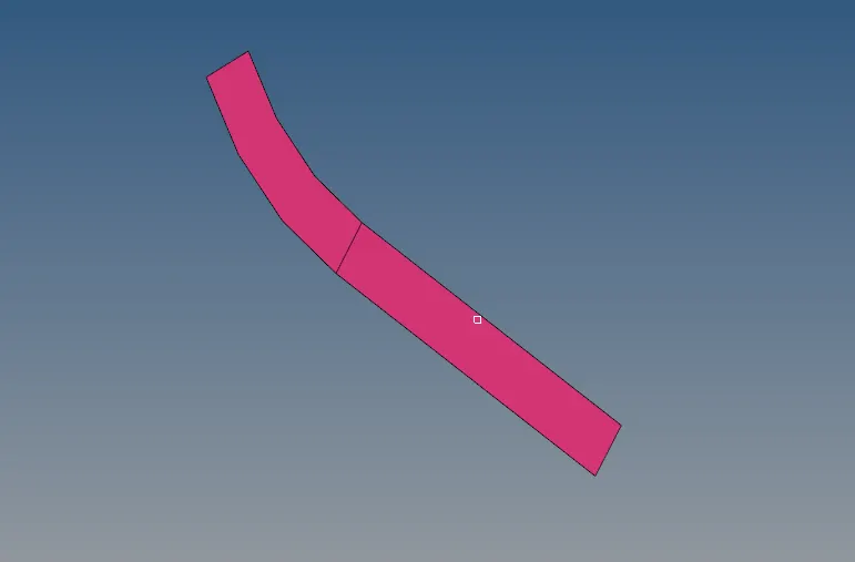
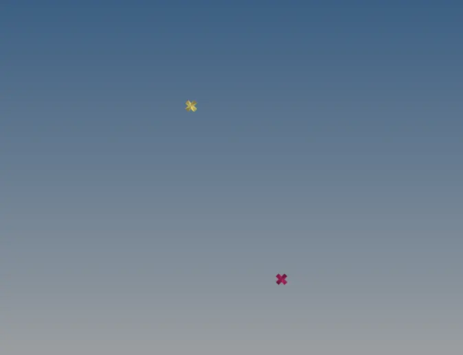
4) Here below, a two points are used to creates the geometry, a red colour points is belongs to Hood inner component and sandal colour points is belongs to Hood outer component.
PROCEDURE TO ATTAINING THE OBJECTIVES :
i) Cleanup the geometry :
1) Make sure delete the solids from model in both hood inner and outer component. We don't need those surface, so we delete those few surface by manually. Cut down near that surface then delete that particular surface, afterwhich closing the surface by using 'filler' option. If a surface might not removing, it showing "T - Junction edge'.
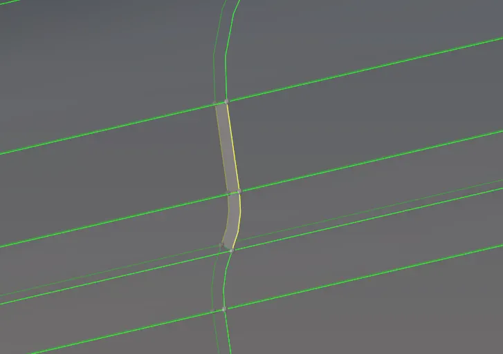
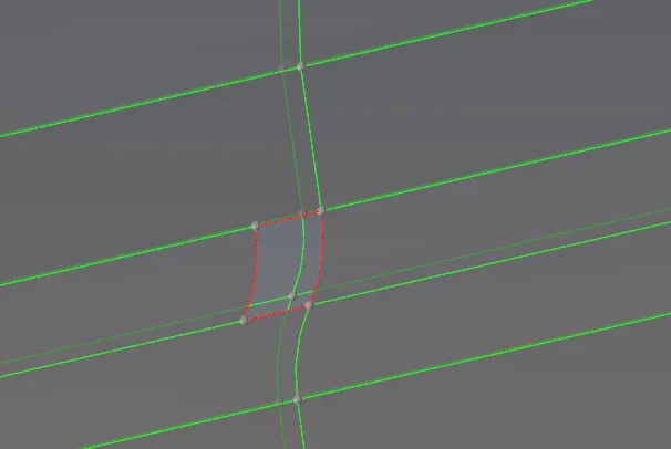
2) After deleting the few surface, there is no need to geometry cleanup. A geometry is perfectly alright to extracting the middle surface.
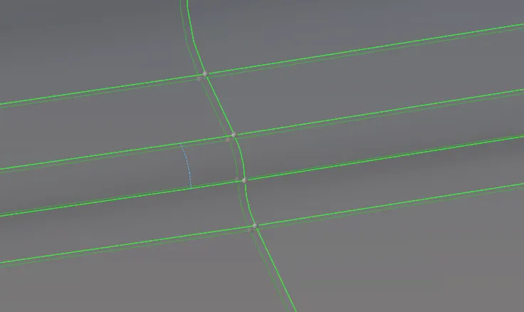
3) Or else simply uncheck the component visible option except those few surface component and then deleting the surface.
ii) Extracting a Middle surface :
Middle Surface for Hood inner component :
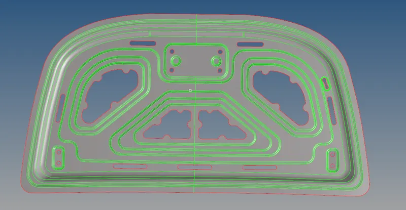
Go to "Mid surface" Panel under the "Geometry" main menu panel, by using "Auto Midsurface" to extract the middle surface from Hood inner component. By using "Offset + Planes + Sweeps" extraction option to generate the midsurface.
Middle Surface for Hood outer component :
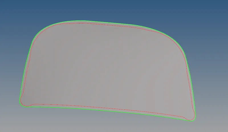
Similarly, do the same procedure to extract the middle surface for Hood outer component.
iii) Cleanup the Geometry for mid surfaces :
Cleanup the geometry for Hood Outer Middle Surface :
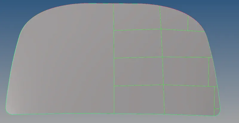
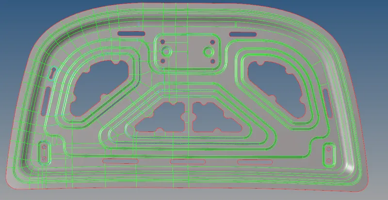
1) We have to cleanup the geometry by manually for getting a proper mesh flow and properly capture the hemming portion around the component. By using some of the few options are used under the "Quick Edge" option.
2) This type of geometry cleanup will help us to getting a proper 'Quad' element flow and also reducing the 'Tria' elements.
3) In this model perfectly symmetrically in shape, so just need to cleanup half a portion and then reflecting to another half portion by using "Reflect" option.
Hemming Edge :
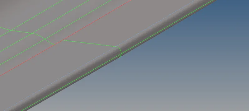
For capturing a hemming edge portion, we have suppressing those corner edges and unsuppressing the middle line around the component.
Cleanuped geometry for Hood Inner Middle Surface :
1) Similarly, this model also symmetrically in shape. So, we want cleanup the geometry at half a portion and also create a some few lines on a surface to capturing a proper flow mesh. After, completing the mesh on half a portion then reflecting the mesh to on another half a portion by using "Reflect" option.
2) If the mesh element are not in proper, we need to draw the sharped edge line between the surface.
iv) Creating a Mesh :
To process of dividing into equivalent number of finite elements with assiocated with nodes is called discritization, this framework is called meshing.
i) Meshing for Hood Outer Component :
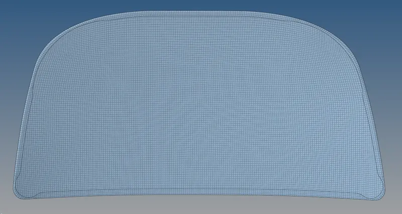
1) Select the surface one by one and creating a mesh on a surface by using "Auto Mesh" option with 5mm element size and "Quad" element type. Remeshing again and again whenever to capturing a proper mesh flow on a surface.
2) And also continuing the same process whenever a elements should merged with mid surface.
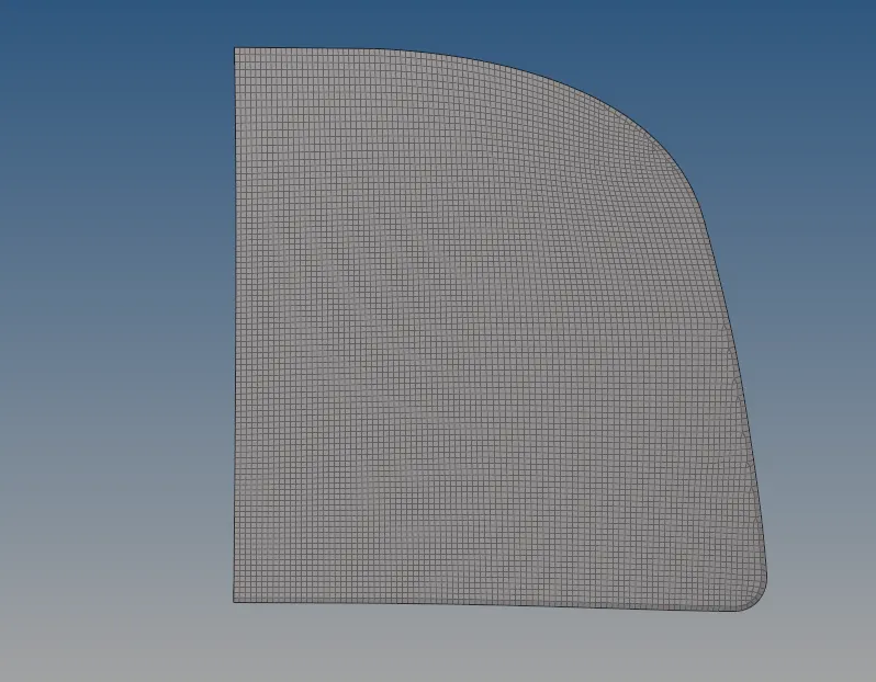
3) After completes the meshing on half a portion, we go to reflect those element into another half a portion by using option called "Reflect".
4) Go to "Tools" option then clicking the "Reflect" option. Select the elements which are want to be reflect, a selected elements are reflected about the Z axis and vector direction is along X axis.

5) Before going to reflecting the elements, select the base node and then click to reflect the elements on another half.
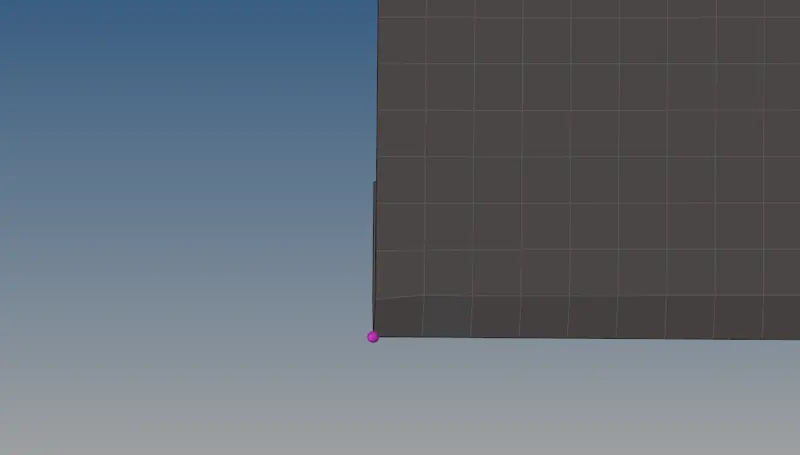
6) After reflecting the elements, make sure reflection is done properly or not. In this case, it's perfect.
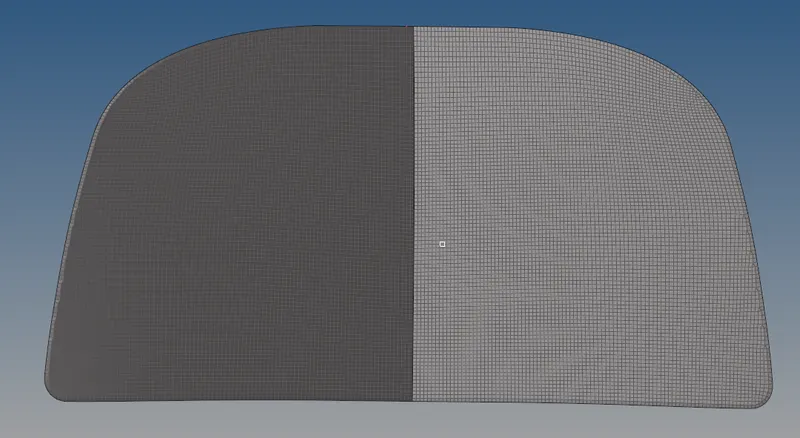
7) After reflecting, a free edges were found at where central or symmetrical line. Go to "tools" option then click the "Edges" panel. Select the component which we want to find, click the "Find edge" option then a "Edges" will showing.
8) Again select the appropriate component, click the Equivalence option to combine element by help of nodes between them.
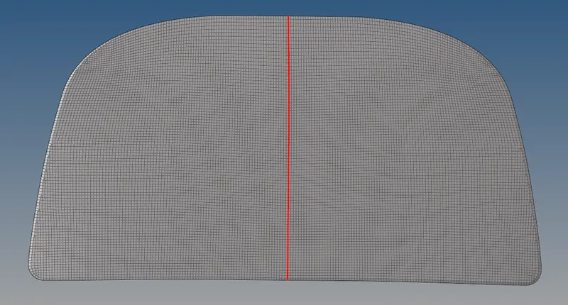
9) After completion of all process, we get the final component with proper meshing.
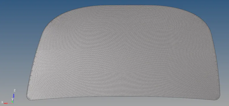
ii) Meshing for Hood Inner component :
1) In this design have some convergence and devergence surface also, it is not possible to getting the proper mesh flow without creating an line between them. If a surface have ideal shapes like sqaure or rectangle, it's possible to getting a perfect mesh throughout the surface and without creating the line between them.
2) So, we necessary to create some few lines on the surface and repetitively remeshing again and agian whenever we get the perfect mesh on it.
3) A geometry is symmetrically in shape except "One slot is located".
4) We choose the right half portion, by selecting surfaces one by one and doing a meshing operation on it. Remeshing again and again whenever it will getting the proper mesh flow.
5) By using 5mm element size and Quad type element, somewhere places Mixed elements are also used.
6) Make sure checking the elements which are satisfying the given quality criteria or not. In this mesh part, there is some break edge were not found when I was use the "Find edge" option.
7) So far we did only half portion, we need to reflecting the elements into another half by using "Reflect" Panel under the "Tools" option.
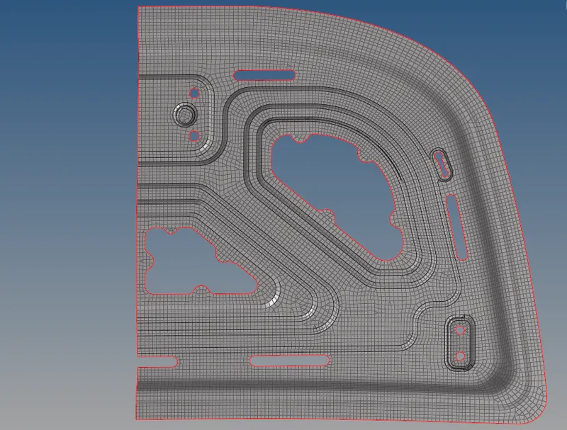
8) Go to "Reflect" panel, select the element which are need to reflect. Make sure ignoring the slot elements which are present, because there no slot have been present on other side.
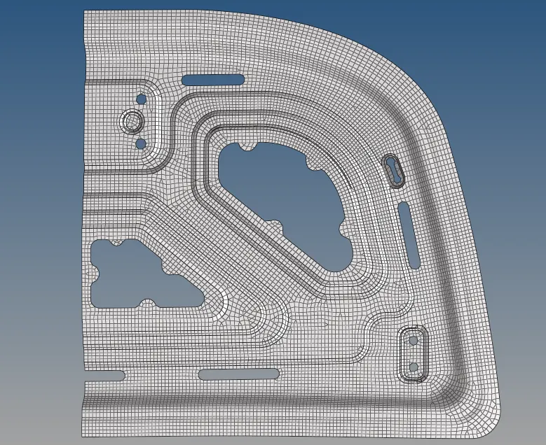
9) Make duplicate element by using original component option. A elements are reflected about the Z axis, vector direction is X axis and remaining things are set into default.
10) Select the base node at anywhere between the central line and then click reflect.
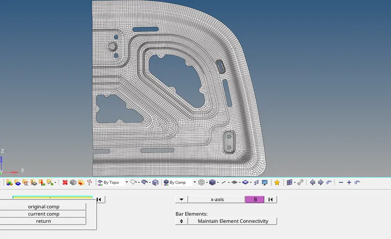
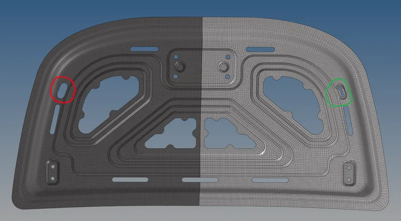
11) After clicking the reflect option, a elements are reflected perfectly. Notice the slot elements are not reflected, because I couldn't select the slot element before execute the reflect option.
12) We need to create a elements on that particular surface by using simple options.
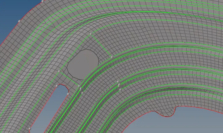
13) First enabling the respective middle surface, make a lines across surface between two lines on both side near a hole.
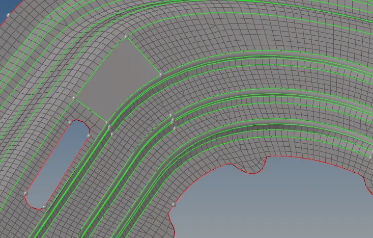
14) By using "Project" option to projecting the nodes on along a line in proper way. Afterthat, deleting the elements which are present in the surface.
15) Creating the mesh on that particular surface by using "Auto Mesh" option.
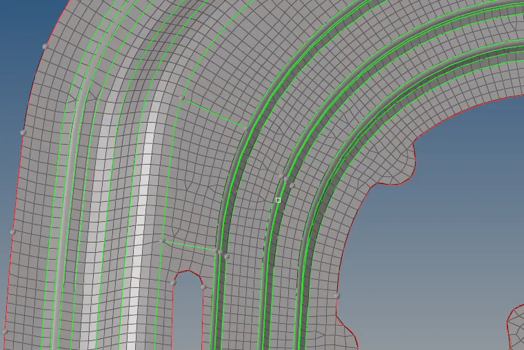
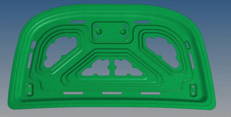
17) After completion of meshing, a mesh elements are looks like exactly same as below image. Notice, there's some break edges are found, so need to equivalence those break lines.
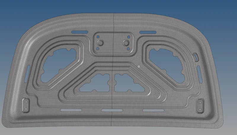
18) Go to "Edges" panel under the" Tools" option, select the appropriate component and click preview the equivalence option. Actually, nodes were created at between elements.
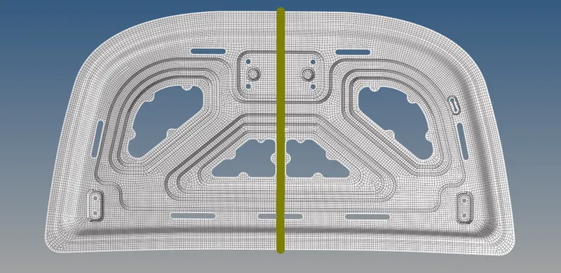
19) After click the preview equivalence, set the tolerance into 0.100 and then click to equivalence. Then only nodes are created perfectly.
20) Afterwhich there s no free edges or break edges were found.

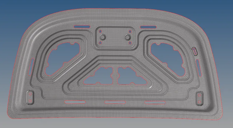
QUALITY CHECKING :
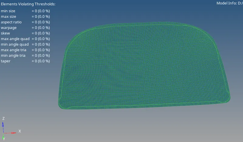
Hood Outer Component Mesh :
A element qualities are satisfying the all element quality parameters.
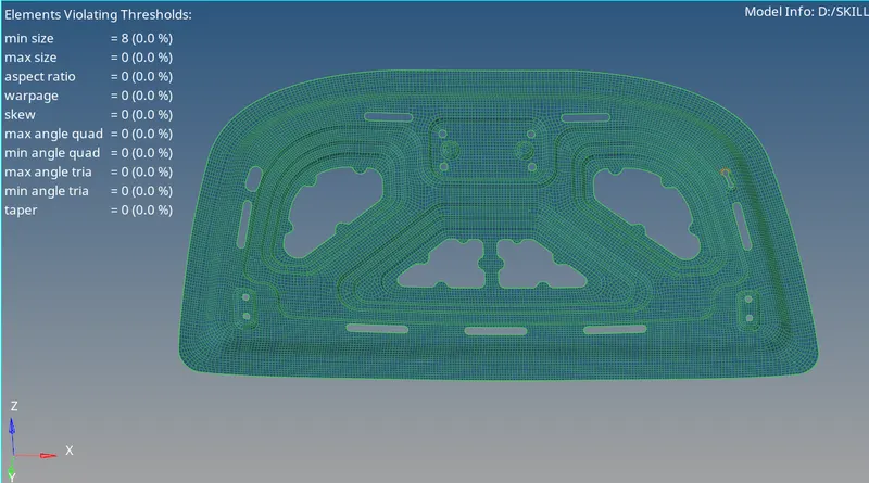
Hood Inner Component Mesh :
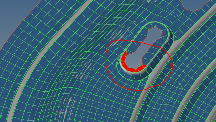
A elements qualities are satifying the quality parameters except small surface. Because, a surface distance less than 3mm length.
Here's a region, surface which is less than the 3mm. So that elements are not comes under the element quality criteria.
CONCLUSION :
Successfully completed the process of extracting mid surface, geometry cleanup on a mid surface and then checking the element quality with different element parameters on given Hood body.
Inner component :
Outer Component :
Hood component :