To model columns for industrial steel structure using TSD
To model columns for industrial steel structure using TSD
Introduction
Tekla Structural Designer is an integrated model-based 3D tool for analysis and design (of both concrete and steel members) in multi-material structures. Features include interactive modeling, automated structural analysis and design, drawing, and report creation.
Tekla Structural Designer way of working
Tekla Structural Designer differs slightly from traditional modeling, analysis and design process.
Traditional modeling, analysis and design process
The traditional modeling, analysis and design process can be summarized in the following phases:
- Provide a way to input or describe the model.
- Analyze the model.
- Design the model.
- Produce calculations.
- Produce drawings.
Process in Tekla Structural Designer
In Tekla Structural Designer, the analysis and design phases are merged into a single process. As a result, the workflow is as follows:
1. Input the geometry and loads
A key requirement these days is BIM integration, or the ability to be able to transfer data from one application to another. Tekla Structural Designer has tools to automatically import model data from Neutral Files and from 3D DXF to facilitate BIM integration. And we can also build the model directly.
Once the physical model has been created, the next step is loading it. Tekla Structural Designer allows you to apply a wide range of loads in a flexible system of load cases. The system contains, among other things, a wind load generator available to automatically create wind load cases. You can also generate load combinations automatically.
We should also consider pattern loading. You can create patterned beam loads automatically, and create patterned slab loads manually for design of slabs.
2. Analyze and design the model
Tekla Structural Designer automatically performs the analyses required to enable member design to proceed. This means that analysis and design are combined into a single automated process. The only exception to this rule is slab design.
3. Produce reports
We can create a wide range of calculations. You can also tailor the calculations extensively to meet your requirements.
4. Produce drawings
We can produce beam and column detail drawings, and member schedules.
PART I:
Aim: To Create column properties for different types of pedestal members and model in the grids created as per the assignment 1
PROCEDURE:
Initially open the Tekla file created in the assignment 1.
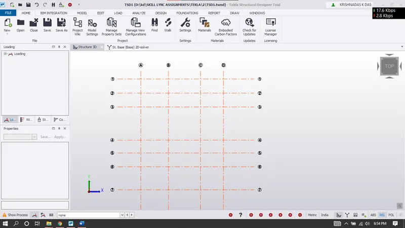
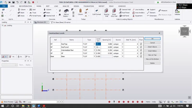
Cross checking was made to confirm the levels of the steel building.
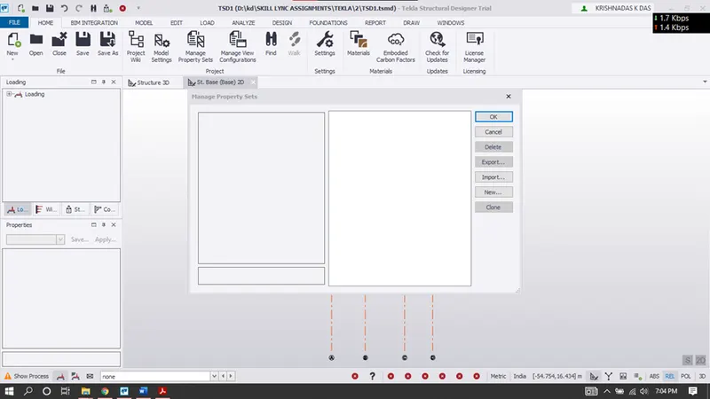
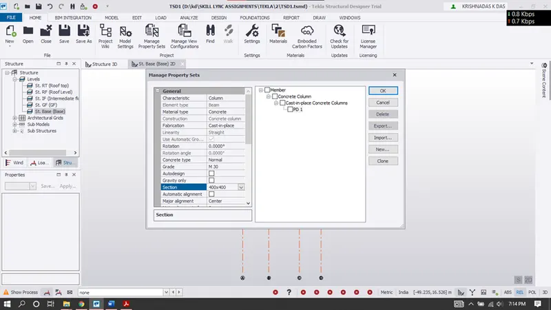
Now to add Pedestal columns in the Home menu click on Manage property sets options and the manage property sets dialogue box appears.
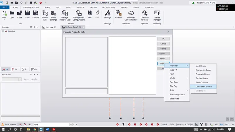
Click on New followed by members and select concrete column.
Rename the column for our own convenience and apply the properties as required on the side.
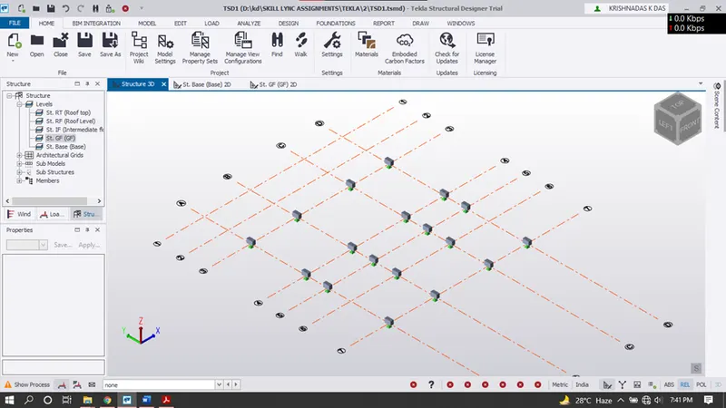
Now using the column option in the ribbon tab under the model menu columns was placed at locations as required. Columns was placed at base floor and till ground floor
PART II
Aim: To create column properties for steel columns and model columns in the grid created as per assignment 1.
Procedure:
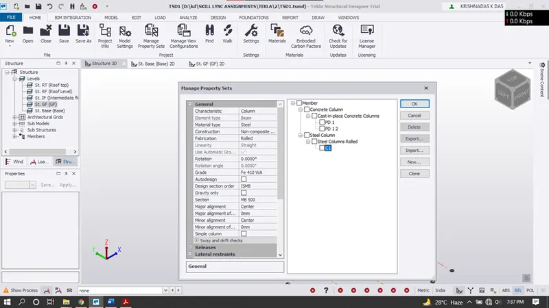
In the similar way concrete column was created steel columns was created and was renamed as C1.
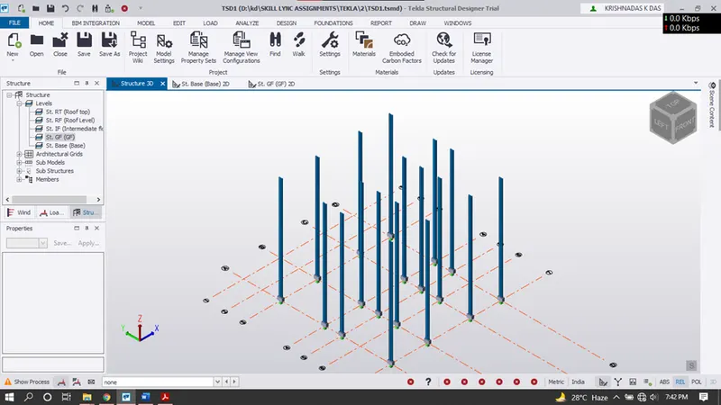
Now using the column option in the ribbon tab under the model menu columns was placed at locations as required. Columns was placed at ground floor and till top roof.
PART III
Aim: To create beam properties and model primary and secondary beams on the ground floor
Procedure:
In the similar way concrete column was created steel beams was created and was renamed as B1 and B2 as shown.
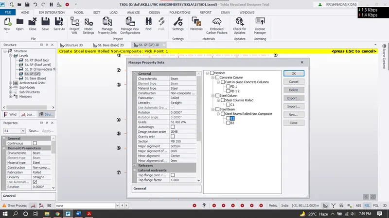
Now using the beam option in the ribbon tab under the model menu beams was placed at locations as required.
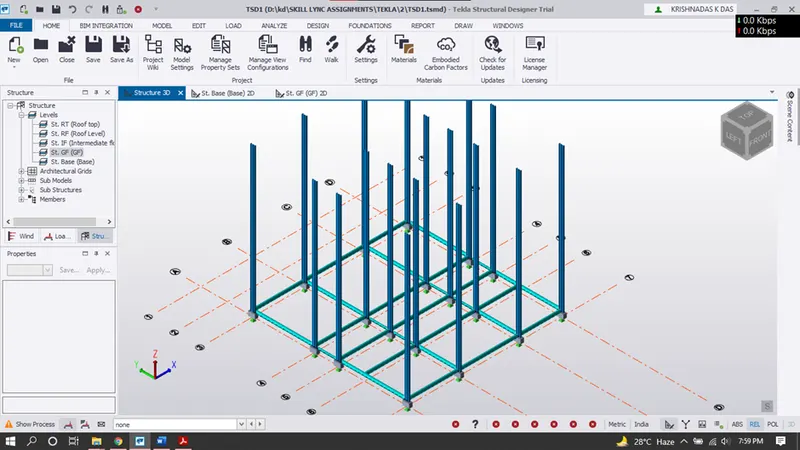
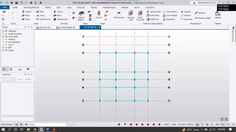
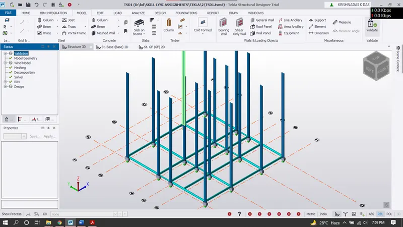
After that the model was validated by clicking on the validate option under the model menu and no errors was found.
Results:
- Created column properties for different types of pedestal members and model in the grids.
- Created column properties for steel columns and model columns in the grid created.
- Create beam properties and model primary and secondary beams on the ground floor